1
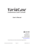
MODELS
45RAD
General Safety and Maintenance Manual
Model 45RAD Aluminum Right Angle Grinder Featuring
an Erickson type collet
MODEL 45RADS with a Steel case. Featuring
an Erickson type collet.
ERICKSON COLLET WITH INTERCHANGEABLE INSERT SIZES RIGHT ANGLE GRINDER
Model
Number
45ARAD
Exhaust
Direction
Throttle
Type
Front
or
Side
(L)
Lever
or
(K)
Safety
Lever
Speed
13500
R.P.M.
(Standard)
Power
Output
0.9 H.P.
(675 W)
Weight
Alum.
CASE
STEEL
CASE
2.8 lb
(1.3 Kg)
3.5 Lbs
(1.6
Kg)
Overall
Length
9.2 Inches
(234 mm)
Housing
Diameter
1.6 Inches
(41 mm)
Working
Air
Consumption
25 cfm
(11.8 L/S)
The Henry Tool Co., Manufactured by Henry Tools
Capacity
Changeable Erickson
Style Insert Collet
Burrs/Mounted Points
Burrs/Mounted points
Matching the Insert Size
498 So. Belvoir Blvd., South Euclid, OH 44121 U.S.A.
Ph: (216) 291-1011 or (800) 826-5257 ● Fax: (216) 291-5949 or (800) 303-2800
Email: [email protected] ● Website: www.Henrytools.com
General Operators Instructions and Service Manual
Model 45ARDS with Erickson style
collet and STEEL case.
HENRY TOOLS, INC. (216) 291-1011 or (800) 826-5257
MODELS
45RAD
Model 45ARAD with Erickson style
collet and Aluminum Case.
Ph:
Model 45ARAD Series featuring an Erickson Style collet.
www.HenryTools.com | Page 76
For additional product information visit our website.
Revised 06/25/12
General Operators Instructions and Service Manual
ITEM
No.
1
2
3
4
4a
4b
5
6
7
8
9
10
11
12
404-2
591028
209-1
209-1/4”
209-3/8”
209-1/8”
404-3
405-15
405-10
404-7
400-G-26
400-51
404-6
405-17DA
13
14
15
16
17
18
19
20
21
22
23
24
25
26
27
28
29
30
404-4
404-40
404-1
700-37
402-132-S
841553
400-G-29
844302
400-G-34
832636
869311
404-19
404-9
592016
594016
404-38
404-39
410-G-17-S
PART NO.
Model 45ARAD with Erickson style
collet and Aluminum Case.
DESCRIPTION
CAP
SCREW
COLLET NUT
COLLET INSERT 1/4”
COLLET INSERT 3/8”
COLLET INSERT 1/8”
BEARING
GEAR SPACER
GEAR (SOLD AS SET)
BEARING
LEVER
O-RING
WAVY WASHER
ERICKSON COLLET
SPINDLE
KEY
DEAD HANDLE
GEAR HEAD HOUSING
PIN
MOTOR HOUSING
BUSHING
THROTTLE VALVE
O-RING
SPRING
GASKET
CAP
REAR END PLATE
REAR BEARING
SNAP RING
O-RING
COVER
SNAP RING
EXHAUST SLEEVE
www.HenryTools.com | Page 77
ITEM
No.
31
32
33
34
35
36
37
38
39
40
PART NO.
402-134
400-7
400-5
400-2-G
400-44
400-6
404-20
400-G-11
404-14
400-10
DESCRIPTION
MUFFLER SCREEN
FRONT END PLATE
ROTOR
CYLINDER with PIN
PIN
VANE (5 are req’d)
GEAR SPACER
BEARING
SPINDLE
KEY
PART NO.
REPAIR KITS
510076
510078
402-26
DESCRIPTION
ITEM NO.
PART NO.
DESCRIPTION
WRENCHES
1100-063
5/8” WRENCH
1100-075
3/4” WRENCH
41
42
REPAIR KIT WITH GEARS
REPAIR KIT WITHOUT GEARS
COMPLETE SAFTETY LEVER ASSEMBLY
For additional product information visit our website.
Revised 06/25/12
Ph:
Model 45ARDS with Erickson style
collet and STEEL case.
HENRY TOOLS, INC. (216) 291-1011 or (800) 826-5257
MODELS
45RAD
General Operators Instructions and Service Manual
Model 45ARAD with Erickson style
collet and Aluminum Case.
SERVICE INSTRUCTIONS
This tool is designed to operate on 90 psig (6.2 bar) maximum
air pressure with 1/4” (8 mm) hose. Do not use a grinder without
recommended wheel guard. Do not use any wheel for which the
operating speed listed is lower than the actual free speed of the
Grinder.
SAFETY
1. Before operation check spindle speed with a tachometer. If
the RPM exceeds the rated speed stamped on tool, servicing is
required. Inspect grinding wheels for bends, chips, nicks, cracks
or severe wear. If the wheel has any of these, or has been soaked
in liquids do not use. On brushes check for loose wires that may fly
off in operation.
2. Start new grinding wheels under a steel bench. Run at full
throttle for one minute.Defective wheels usually come apart immediately. When starting a cold wheel apply to work slowly, allow
wheel to warm gradually.
3. Model 45ARAD grinders equipped with erickson collets
intended for mounted wheels,points and carbide burrs. They
are not guarded for type 1 wheels. If you have a type 1 wheel
application,please purchase a guard (4504,4505,etc.)
4. Safety levers are available from the manufacturer.(402-26).
Before mounting or removing a carbide burr or mounted point,
disconnect grinder from air supply. Wear safety goggles and other
protective clothing. Continuous exposure to vibration may cause
injury to your hands and arms.(See regulations.)
5. Properly maintained air tools are less likely to fail or cause
accidents. If tool produces an unusual sound or vibrations repair
immediately.
DISASSEMBLY
PLEASE NOTE: The brass spacers that were installed by the
factory are necessary for this tool to operate efficiently.
When disassembling this tool examine how spacers are
arranged. They must be installed exactly the same way.
Failure to do this will cause improper gear spacing, which
causes pre-mature tool failure.
1. Disconnect air & remove all wheels and accessories. Softly secure anglehead in vise on dead handle boss. Unscrew and remove
case(402-132) Never squeeze anglehead(404-1) in vise. This will
distort bearings and ruin gear alignment.
2. Remove deflector (410-G-17-S).
3. Pull motor from right angle head. Be careful to note location of shims. Remove snap ring (404-39),wafer(404-38),Oring(594016), and snap ring (592016).(Some of these may not be
present).
4. Install brass or aluminum jaws in vise. Grasp the O.D. of
cylinder(400-2-G)and end plate(404-19). Using a 3/16” punch, tap
spindle out rear bearing (404-9)
5. Remove cylinder, blades(400-6).
6. With rotor (400-5) still on spindle (404-14), grasp the rotor in
vise snugly and remove pinion gear(405-10).
7. Remove rotor(400-5) Remove key and front thrust
plate(400-7). 9. Press bearing (400-G-11) off of spindle.
8. Secure angle head in vise and unscrew cap (404-2). Remove
from vise. DO NOT remove collet nut (209-1) during the repair
process. (We are trying to protect the spindle threads from damage). Tap on spindle with a plastic hammer The spindle assembly
and spring washer (404-6) will slide out.
www.HenryTools.com | Page 78
9. Clamp flats of spindle(405-17DA) in vise. Using a plastic
hammer, tap evenly on O.D. of bearing cap until free of bearing (404-3). Note position of shims. Using a 9/64” T-Handle
hex wrench unscrew (591028) screw.
10.Press bearing (404-3) off spindle. Support bearing (404-7)
and press spindle through with 1/4” punch. This will remove
gear (405-10) and bearing(404-7).
11.Remove key (404-4).
ASSEMBLY
1. Support front bearing(400-G-11) on drill block. Press
spindle(404-14)through bearing until it bottoms on shoulder.
2. Slide front thrust(400-7)over the spindle and onto front
bearing. Place key(400-10) into keyway in spindle. Slide rotor
down over shaft.
3. Grasp rotor in vise snugly and replace pinion gear(405-10)
and wrench firmly.
4. Support bearing and pinion gear in downward position.
Place five blades(400-6) in slots.
5. Slip cylinder(400-2-G) over rotor. Install rear
thrust(404-19) locating cylinder pin in small hole of rear
thrust plate (404-19). Place bearing (404-9) in rear thrust
and tap into place with suitable bearing driver. Using pliers
place snap ring(592016) in spindle groove.[(May be snap ring
(404-39)]
6. Support bearing(404-7) on inner race. (Make sure nut
209-1 is installed on spindle). Press spindle (405-17DA)
through bearing (404-7) until it bottoms on shoulder of
spindle.
7. Install key (404-4) and line up with keyway of ring
gear(405-10). Support gear on inner diameter and press
spindle through.
8. Replace gear spacer ring (405-15) on spindle.
9. Support threaded end of spindle and press on bearing(404-3). Tighten screw (591028) into end of spindle. Press
spindle assembly into cap(404-2) Grease gear.
10.Install spring washers(404-6) into angle head(404-1). Install spindle assembly into angle head housing, secure in vise
and tighten cap (404-2).
11.Re-Locate angle head in vise-so that the motor can be
installed vertically.
12.Replace shim(404-20) exactly as it was originally installed.
Jiggle greased pinion assembly into angle head while turning
spindle(404-5)-so that gears mesh. Tap lightly on rear of motor to insure that is fully seated.
13.Install exhaust deflector (410-G-17-S). Place Oring(400-51) on motor case(402-132) and screw onto angle
head. The deflector should be snug, but can be turned.
14.Place a few drops of oil into motor inlet.
15.To check throttle valve, unscrew plug(869311) and lift out
spring and valve.
16.Replace O-ring if worn.
17.Replace guard on tool.
18.CHECK RPM WITH TACHOMETER.TOOL MUST RUN AT
OR BELOW SPEED THAT IS STAMPED ON TOOL.
For additional product information visit our website.
Revised 06/25/12
Ph:
Model 45ARDS with Erickson style
collet and STEEL case.
HENRY TOOLS, INC. (216) 291-1011 or (800) 826-5257
MODELS
45RAD