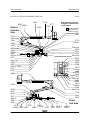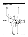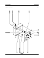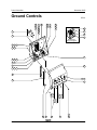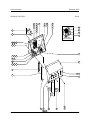
1
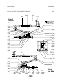
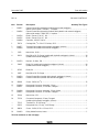
Parts and Service Manual
Supplement
Part No. 104980
Rev A
November 2005
November 2005
Important
Read, understand and obey the safety rules and
operating instructions in the TMZ-34/19 Operator's
Manual before attempting any maintenance or
repair procedure.
This manual provides detailed parts and service
information for qualified service professionals.
This Parts and Service Manual Supplement
provides service parts information and electrical
schematics for the recently released TMZ-34/19
Control System, which are not included in your
parts or service manuals. Please add this parts
information and electrical schematics to the parts
and service manuals for your machine.
Basic mechanical, hydraulic and electrical
skills are required to perform most procedures.
However, several procedures require specialized
skills, tools, lifting equipment and a suitable
workshop. In these instances, we strongly
recommend that maintenance and repair be
performed at an authorized Genie dealer
service center.
Technical Publications
Genie Industries has endeavored to deliver the
highest degree of accuracy possible. However,
continuous improvement of our products is a Genie
policy. Therefore, product specifications
are subject to change without notice.
Readers are encouraged to notify Genie of errors
and send in suggestions for improvement. All
communications will be carefully considered for
future printings of this and all other manuals.
Contact Us:
Copyright © 1998 by Genie Industries
104980 Rev A November 2005
First Edition, First Printing
PO Box 97030
Redmond, WA 98073-9730 USA
"Genie" is a registered trademark of Genie
Industries in the USA and many other countries.
"TMZ" is a trademark of Genie Industries.
www.genieindustries.com
e-mail: [email protected]
Printed on recycled paper
Printed in U.S.A.
2
TMZ-34/19
Part No. 104980
November 2005
Table of Contents
Introduction
Important Information ........................................................................................ 2
Section 1
Section 2
Part No. 104980
Rev
Service Parts
A
Decals .............................................................................................................. 4
A
Platform Controls ............................................................................................ 10
A
Ground Controls ............................................................................................. 14
Rev
Schematics
A
Introduction ..................................................................................................... 20
A
Wiring Diagram - Platform Controls ................................................................ 21
A
Wiring Diagrams - Ground Controls
Models with Manual Outriggers....................................................................... 22
A
Wiring Diagrams - Ground Controls
Models with Hydraulic Outriggers ................................................................... 26
A
Electrical Schematic Models with Manual Outriggers....................................................................... 30
A
Electrical Schematic Models with Hydraulic Outriggers ................................................................... 32
TMZ-34/19
3
Parts Information
November 2005
Decals
REV A
(before serial number T3400-001)
37145
28161
62066
97777
Ground
Controls
Side
Shading indicates
that the decal is
hidden from view.
37145
28161
72899
37145
97847
49918
52008
27564
48733
48734
97778
Serial Label
28161
48723 or
52557
35579 or
62722
48727
Safety Tape
48726
52475
72897 or 72908
62707
52475
62066
Safety Tape
48719
28236
28176
97846
37052
or 44248
44986
or 37051
40434
Safety Tape
28174
or 28235
40434
Safety Tape
27564
28175
37145
28164
28161
28171
28157
31060
Safety
Tape
4
62707
52495
52475
72897 or
72908
Power
Unit Side
52475
52496
Safety
Tape
TMZ-34/19
28174 or
28235
43658 or
44980
Part No. 104980
November 2005
Parts Information
DECALS
REV A
Item
Part No.
Description
Quantity This Figure
—
48729
Decal Kit, Safety/Instructional (includes items 1-5, 7-8, 10-11, 15-16, 21, 23-31, 37
and 41-42) ................................................................................................................. —
1
27564
Danger - Electrocution Hazard .................................................................................. 2
2
28157
Label - Dexron ............................................................................................................ 1
3
28161
Warning - Crushing Hazard ........................................................................................ 4
4
28164
Notice - Hazardous Materials ..................................................................................... 1
5
28171
Label - No Smoking .................................................................................................... 1
6
28174
Label - Power to Platform, 230V AC ........................................................................... 2
7
28175
Caution - Compartment Access .................................................................................. 1
8
28176
Notice - Missing Manuals ........................................................................................... 1
9
28235
Label - Power to Platform, 115V AC ........................................................................... 2
10
28236
Warning - Failure To Read . . . ................................................................................... 1
11
31060
Danger - Do Not Alter Limit Switch ............................................................................. 1
12
35579
Notice - Max Cap, Hook, 500 lbs / 227 kg .................................................................. 1
13
37051
Notice - Side Force, 150 lbs / 667 N, ANSI & CSA ..................................................... 1
14
37052
Notice - Max Cap, 500 lbs / 227 kg ............................................................................. 1
15
37145
Label - Manual Lowering ............................................................................................ 4
16
40434
Label - Lanyard Anchorage ........................................................................................ 2
17
44248
Notice - Max Cap, 440 lbs / 200 kg ............................................................................. 1
18
43658
Notice - Power to Battery Charger, 230V AC ............................................................. 1
19
44980
Notice - Power to Battery Charger, 115V AC ............................................................. 1
20
44986
Notice - Side Force, 90 lbs / 400N, CE ....................................................................... 1
21
48719
Danger - General Safety, Platform ............................................................................. 1
22
48723
Label - Parking Brake (hydraulic), ANSI & CSA ......................................................... 1
23
48726
Notice - Battery Charger Operating Instructions ......................................................... 1
This list continues on the next page.
Part No. 104980
TMZ-34/19
5
Parts Information
November 2005
DECALS (BEFORE SERIAL NUMBER T3400-001)
REV A
37145
28161
62066
97777
Ground
Controls
Side
Shading indicates
that the decal is
hidden from view.
37145
28161
72899
37145
97847
49918
52008
27564
48733
48734
97778
Serial Label
28161
48723 or
52557
35579 or
62722
48727
Safety Tape
48726
52475
72897 or 72908
62707
52475
62066
Safety Tape
48719
28236
28176
97846
37052
or 44248
44986
or 37051
40434
Safety Tape
28174
or 28235
40434
Safety Tape
27564
28175
37145
28164
28161
28171
28157
31060
Safety
Tape
6
62707
52495
52475
72897 or
72908
Power
Unit Side
52475
52496
Safety
Tape
TMZ-34/19
28174 or
28235
43658 or
44980
Part No. 104980
November 2005
Parts Information
REV A
Item
DECALS (BEFORE SERIAL NUMBER T3400-001)
Part No.
Description
Quantity This Figure
24
48727
Danger - Battery/Charger Safety ................................................................................ 1
25
48733
Danger - Tip-over (batteries) ...................................................................................... 1
26
48734
Notice - Battery Connection Diagram ......................................................................... 1
27
49918
Notice - Material Lifting Operation .............................................................................. 1
28
52008
Danger - General Safety, Ground ............................................................................... 1
29
52475
Label - Transport Tie-down ........................................................................................ 4
30
52495
Notice - Manual Lowering Instructions ........................................................................ 1
31
52496
Notice - Manual Rotation Instructions ......................................................................... 1
32
52557
Label - Parking Brake (mechanical), CE ..................................................................... 1
33
62066
Cosmetic - Genie TMZ-34/19 ..................................................................................... 2
34
62707
Warning - Towing Hazard ........................................................................................... 2
35
62722
Notice - Max Cap, Hook, 440 lbs / 200 kg .................................................................. 1
36
72897
Notice - Tire Specification, ANSI & CSA ..................................................................... 2
37
72899
Notice - Transport Instructions ................................................................................... 1
38
72908
Notice - Tire specification, CE .................................................................................... 2
39
97777
Platform Control Panel ............................................................................................... 1
40
97778
Ground Control Panel ................................................................................................. 1
41
97846
Notice - Operating Instructions, Platform .................................................................... 1
42
97847
Notice - Operating Instructions, Ground ..................................................................... 1
Part No. 104980
TMZ-34/19
7
Parts Information
November 2005
Decals
REV A
(after serial number T3499-769)
65307
Ground
Controls
Side
28161
62066
37145
97777
37145
97847
Note: Optional hydraulic
outriggers have two each
of decal 28161.
Shading indicates
that the decal is
hidden from view.
72971
49918
37145
28161
72899
97778
or 97814
52008
27564
48733
48734
48723 or
52557
35579 or 62722
48727
Safety Tape
48726
52475
72897 or 72908
62707
52475
Serial Label
62719
62719
28161
Safety Tape
48719
28236
28176
97846
37052
or 44248
44986
or 65309
40434
72971
Safety Tape
44981
or 65056
28174
or 28235
40434
Safety Tape
62066
27564
52496
28175
28164
28171
44981 or
65056
31060
72897
62707
28157
Safety
or 72908
or 82366 Tape 52475
65303
8
37145
28161
65307
Power
Unit Side
52475
TMZ-34/19
Safety
Tape
28174 or
28235
43658 or
44980
Part No. 104980
November 2005
Parts Information
DECALS (AFTER SERIAL NUMBER T3499-769)
REV A
Item
Part No.
Description
Quantity This Figure
—
72903
Decal Kit, Safety/Instructional (includes items 1, 3-5, 7-8, 10-11,14-15, 21, 23-27,
28-30, 33-34, 37-38, 40, 43-44 and 48-49) ................................................................ —
1
27564
Danger - Electrocution Hazard ................................................................................... 2
2
28157
Label - Dexron ............................................................................................................ 1
3
28161
Warning - Crushing Hazard
(models with manual outriggers) ................................................................................. 4
(models with hydraulic outriggers) ............................................................................ 12
4
28164
Notice - Hazardous Materials ..................................................................................... 1
5
28171
Label - No Smoking .................................................................................................... 1
6
28174
Label - Power to Platform, 230V AC ........................................................................... 2
7
28175
Caution - Compartment Access .................................................................................. 1
8
28176
Notice - Missing Manuals ........................................................................................... 1
9
28235
Label - Power to Platform, 115V AC ........................................................................... 2
10
28236
Warning - Failure To Read ......................................................................................... 1
11
31060
Danger - Do Not Alter Limit Switch ............................................................................. 1
12
35579
Notice - Max Cap, Hook, 500 lbs / 227 kg .................................................................. 1
13
37052
Notice - Max Cap, 500 lbs / 227 kg ............................................................................. 1
14
37145
Label - Manual Lowering ............................................................................................ 4
15
40434
Label - Lanyard Anchorage ........................................................................................ 2
16
43658
Notice - Power to Battery Charger, 230V AC ............................................................. 1
17
44248
Notice - Max Cap, 440 lbs / 200 kg ............................................................................. 1
18
44980
Notice - Power to Battery Charger, 115V AC ............................................................. 1
19
44981
Label - Air Line to Platform ......................................................................................... 2
20
44986
Notice - Side Force, 90 lbs / 400 N, CE ...................................................................... 1
21
48719
Danger - General Safety, Platform ............................................................................. 1
22
48723
Label - Parking Brake (hydraulic), ANSI & CSA ......................................................... 1
This list continues on the next page.
Part No. 104980
TMZ-34/19
9
Parts Information
November 2005
DECALS (AFTER SERIAL NUMBER T3499-769)
65307
Ground
Controls
Side
28161
62066
REV A
37145
97777
37145
97847
Note: Optional hydraulic
outriggers have two each
of decal 28161.
Shading indicates
that the decal is
hidden from view.
72971
49918
37145
28161
72899
97778
or 97814
52008
27564
48733
48734
48723 or
52557
35579 or 62722
48727
Safety Tape
48726
52475
72897 or 72908
62707
52475
Serial Label
62719
62719
28161
Safety Tape
48719
28236
28176
97846
37052
or 44248
44986
or 65309
40434
72971
Safety Tape
44981
or 65056
28174
or 28235
40434
Safety Tape
62066
27564
52496
28175
28164
28171
44981 or
65056
31060
72897
62707
28157
Safety
or 72908
or 82366 Tape 52475
65303
10
37145
28161
65307
Power
Unit Side
52475
TMZ-34/19
Safety
Tape
28174 or
28235
43658 or
44980
Part No. 104980
November 2005
Parts Information
REV A
Item
DECALS (AFTER SERIAL NUMBER T3499-769)
Part No.
Description
Quantity This Figure
23
48726
Notice - Battery Charger Operating Instructions ......................................................... 1
24
48727
Danger - Battery/Charger Safety ................................................................................ 1
25
48733
Danger - Tip-over (batteries) ...................................................................................... 1
26
48734
Battery Connection Diagram ...................................................................................... 1
27
49918
Notice - Material Lifting Operation .............................................................................. 1
28
52008
Danger - General Safety, Ground ............................................................................... 1
29
52475
Label - Transport Tie-down ........................................................................................ 4
30
52496
Notice - Manual Rotation Instructions ......................................................................... 1
31
52557
Label - Parking Brake (mechanical), CE ..................................................................... 1
32
62066
Cosmetic, Genie TMZ-34/19 ...................................................................................... 2
33
62707
Warning - Towing Hazard ........................................................................................... 2
34
62719
Label - Arrow .............................................................................................................. 2
35
62722
Notice - Max Cap, Hook, 440 lbs / 200 kg .................................................................. 1
36
65056
Label - Water Line to Platform .................................................................................... 2
37
65303
Notice - Manual Lowering Instructions ........................................................................ 1
38
65307
Caution - Forklift Pockets ........................................................................................... 2
39
65309
Notice - Side Force, 90 lbs / 400 N ............................................................................. 1
40
72899
Warning - Transport Instructions ................................................................................ 1
41
72897
Notice - Tire Specifications, ANSI & CSA ................................................................... 2
42
72908
Notice - Tire Specifications, CE .................................................................................. 2
43
72971
Label - Transport to Canada ....................................................................................... 2
44
82366
Label - Chevron Rykon ............................................................................................... 1
45
97777
Platform Control Panel ............................................................................................... 1
This list continues on the next page.
Part No. 104980
TMZ-34/19
11
Parts Information
November 2005
REV A
DECALS (AFTER SERIAL NUMBER T3499-769)
65307
Ground
Controls
Side
28161
62066
37145
97777
37145
97847
Note: Optional hydraulic
outriggers have two each
of decal 28161.
Shading indicates
that the decal is
hidden from view.
72971
49918
37145
28161
72899
97778
or 97814
52008
27564
48733
48734
48723 or
52557
35579 or 62722
48727
Safety Tape
48726
52475
72897 or 72908
62707
52475
Serial Label
62719
62719
28161
Safety Tape
48719
28236
28176
97846
37052
or 44248
44986
or 65309
40434
72971
Safety Tape
44981
or 65056
28174
or 28235
40434
Safety Tape
62066
27564
52496
28175
28164
28171
44981 or
65056
31060
72897
62707
28157
Safety
or 72908
or 82366 Tape 52475
65303
12
37145
28161
65307
Power
Unit Side
52475
TMZ-34/19
Safety
Tape
28174 or
28235
43658 or
44980
Part No. 104980
November 2005
Parts Information
REV A
Item
DECALS (AFTER SERIAL NUMBER T3499-769)
Part No.
Description
Quantity This Figure
46
97778
Ground Control Panel ................................................................................................. 1
47
97814
Ground Control Panel (models with hydraulic outriggers) ........................................... 1
48
97846
Notice - Operating Instructions, Platform .................................................................... 1
49
97847
Notice - Operating Instructions, Ground ..................................................................... 1
Part No. 104980
TMZ-34/19
13
Parts Information
November 2005
Platform Controls
REV A
1
4
7
4
2
5
8
6
3
6
9
11 10
23 24 25 26 27
12
13
21
20
19
18
22
14
17
16
15
TMZ-34/19
14
Part No. 104980
November 2005
Parts Information
PLATFORM CONTROLS
REV A
Item
Part No.
Description
Quantity This Figure
—
—
—
104858
104859
104749
Platform Control Box Assembly - Complete .............................................................. —
Platform Control Cable Assembly (477 inches) ......................................................... —
Platform Connector Mount ......................................................................................... —
1
6090
Screw - HHC, 1/4 -20 x 0.75 inch, GR 5 ...................................................................... 3
2
66866
Button - Joystick Mount .............................................................................................. 3
3
6889
Low Profile Nylock Nut, 1/4 -20 ................................................................................... 3
4
49820
Screw - PHPM, 6-32 x 0.5 inch, GR 2 ........................................................................ 4
5
62819
Keeper - Over Center Latch ....................................................................................... 1
6
12344
Nylock Nut, 6-32 ......................................................................................................... 4
7
104865
Platform Control Box .................................................................................................. 1
8
69773
Weatherstripping - Ribbed ............................................................................. 34 inches
9
104629
Platform Control Box Lid ............................................................................................. 1
10
49819
Screw - PHPM, 10-32 x 0.5 inch, GR 2 ...................................................................... 4
11
23405
Nutsert, 10-32............................................................................................................. 4
12
23134
Battery Charge Indicator ............................................................................................. 1
13
104870
Push Button, Momentary ............................................................................................ 7
14
104327
Potentiometer Assembly ............................................................................................ 1
15
—
—
66812
66817
66818
Push Button - Red Mushroom Head ........................................................................... 1
Base - Push Button (includes 1 N.C. contact) ........................................................... —
N.C. Contact .............................................................................................................. —
16
—
45383
72326
Alarm - Warble Tone, 5-30V DC (includes retainer nut) ............................................. 1
Nut - Retainer ............................................................................................................ —
17
73475
Plug Boot, 4 way ........................................................................................................ 1
18
6578
Cable Tie, 7 3/8 inches .............................................................................................. 18
19
60434
Grey Plug, 12 way, 14-18 Gauge ............................................................................... 1
20
73714
Socket - Terminal, 16-18 Gauge ............................................................................... 12
21
60435
Secondary Lock ......................................................................................................... 1
22
96386
Wire Cable, 18/12 Gauge ............................................................................ 120 inches
This list continues on the next page.
Part No. 104980
TMZ-34/19
15
Parts Information
November 2005
PLATFORM CONTROLS
REV A
1
4
7
4
2
5
8
6
3
6
9
11 10
23 24 25 26 27
12
13
21
20
19
18
22
16
17
16
15
TMZ-34/19
14
Part No. 104980
November 2005
Parts Information
REV A
Item
PLATFORM CONTROLS
Part No.
Description
Quantity This Figure
23
—
—
76480
76478
76481
Terminal Block - Wieland, End Plate .......................................................................... 1
Terminal Block - Wieland, 4 hole ............................................................................... —
Terminal Block - Wieland, End Block ......................................................................... —
24
19251
Butt Splice, 18-22 Gauge ........................................................................................... 3
25
13083
Diode, 2A ................................................................................................................... 5
26
99195
Resistor, 5.6 ohm, 2W ................................................................................................ 2
27
104335
Diode - Zeener, 5.1V DC, 1W ..................................................................................... 1
Part No. 104980
TMZ-34/19
17
Parts Information
November 2005
Ground Controls
17
1
4
2
5
3
6
REV A
9
10
10
13
11
12
14
16
15
7
17
8
18
16
19
Models With
Manual Outriggers
38 39 40
36 37
20
13 35 15
34 11
33
21
13 32 15
31
23 22
30
24
13
29
18
28
27
TMZ-34/19
26
25
Part No. 104980
November 2005
Parts Information
GROUND CONTROLS
REV A
Item
Part No.
Description
Quantity This Figure
—
104857
—
104856
—
—
—
104334
104335
104880
Ground Control Box Assembly (models with manual outriggers)
(before serial number TZ3400-1) - Complete ............................................................ —
Ground Control Box Assembly (models with hydraulic and manual outriggers)
(after serial number T3499-796) - Complete .............................................................. —
Diode - Zeener, 3.3V DC, 1W ..................................................................................... 1
Diode - Zeener, 5.1V DC, 1W ..................................................................................... 1
Capacitor, 100 MF, 50V AC ........................................................................................ 1
1
71874
Carriage Bolt, 3/16 -24 x 1.25 inches, GR 2 ................................................................. 2
2
—
104877
104884
Terminal Rail (models with hydraulic outriggers) (shown) ........................................... 1
Terminal Rail (models with manual outriggers) .......................................................... —
3
5365
Nylock Nut, 10-24 ....................................................................................................... 2
4
19251
Butt Splice, 18-22 Gauge (models with hydraulic outriggers) (shown) ...................... 24
(models with manual outriggers) ............................................................................... 15
5
104333
Resistor, 1k Ohm, 2W ................................................................................................ 3
6
13083
Diode, 2A (models with hydraulic outriggers) (shown) .............................................. 54
(models with manual outriggers) ............................................................................... 35
7
45782
Diode, 6A ................................................................................................................... 2
8
6687
Butt Splice, 18-22 Gauge ........................................................................................... 1
9
—
104650
104860
Ground Control Box (models with hydraulic outriggers) (shown) ................................ 1
Ground Control Box (models with manual outriggers) ............................................... —
10
88288
Screw - PHPM, 4 x 3/8 .............................................................................................. 12
11
—
104994
104871
Receptacle Connector Assembly, 23 way .................................................................. 1
Receptacle Connector, 23 Position, Flanged ............................................................. —
12
—
104998
104872
Receptacle Connector Assembly, 35 way, White ....................................................... 1
Receptacle Connector, 35 Position, Flanged ............................................................. —
13
12344
Nylock Nut, 6-32 ......................................................................................................... ?
14
73730
—
—
73713
54255
Connector Receptacle, 12 way, Flanged
(models with hydraulic outriggers) (shown) ................................................................ 1
Terminal Pin, 16-18 Gauge ....................................................................................... —
Receptacle Lock, 12 way, 14-18 Gauge .................................................................... —
15
49820
Screw - PHPM, 6-32 x 0.5 inch, GR 2 ........................................................................ 6
16
104493
Relay Holder Bracket, Lower ...................................................................................... 1
This list continues on the next page.
Part No. 104980
TMZ-34/19
19
Parts Information
November 2005
GROUND CONTROLS
17
REV A
1
4
2
5
3
6
9
10
10
13
11
12
14
16
15
7
17
8
18
16
19
Models With
Manual Outriggers
38 39 40
36 37
20
13 35 15
34 11
33
21
13 32 15
31
23 22
30
24
13
29
20
28
27
TMZ-34/19
26
25
Part No. 104980
November 2005
Parts Information
REV A
GROUND CONTROLS
Item
Part No.
Description
Quantity This Figure
17
104706
Relay Mount Bracket, Upper ...................................................................................... 1
18
104993
Relay Mount Bracket (models with manual outriggers) ............................................... 1
19
104491
Relay Holder Bracket, Upper (models with manual outriggers) .................................. 1
20
—
45383
72326
Warble Tone Alarm, 5-30V DC (includes retainer nut) ................................................ 1
Nut - Retainer ............................................................................................................ —
21
—
104649
104868
Ground Control Box Lid (models with hydraulic outriggers) (shown) .......................... 1
Ground Control Box Lid (models with manual outriggers) .......................................... —
22
—
—
96008
83093
37947
Key Switch, 3 Position (includes 1 pair of keys) ......................................................... 1
Key (single) ............................................................................................................... —
Key, Package of 10 ................................................................................................... —
23
96009
Rubber Washer .......................................................................................................... 1
24
104870
Push Button, Momentary (models with hydraulic outriggers) (shown) ...................... 12
(models with manual outriggers) ................................................................................. 7
25
11803
Screw - RHSM, 6-32 x 1 inch (models with hydraulic outriggers) (shown) ................. 2
(models with manual outriggers) ................................................................................. 3
26
99084
Time Delay Module (models with hydraulic outriggers) .............................................. 1
27
104876
Time Delay Module .................................................................................................... 2
28
—
—
66812
66817
66818
Push Button - Red Mushroom Head ........................................................................... 1
Base - Push Button (includes 1 N.C. contact) ........................................................... —
N.C. Contact .............................................................................................................. —
29
104714
Relay, 24V DC (models with hydraulic outriggers) (shown) ...................................... 22
(models with manual outriggers) ............................................................................... 17
30
104879
Relay Holder Bracket, Upper (models with hydraulic outriggers) ................................ 2
(models with manual outriggers) ................................................................................. 1
31
104878
Relay Mount Bracket, Upper (models with hydraulic outriggers) ................................ 2
(models with manual outriggers) ................................................................................. 1
32
—
—
73733
83130
54255
Receptacle Connector, 12 way, Flanged (models with hydraulic outriggers) .............. 1
Terminal Pin, 16-18 Gauge ....................................................................................... —
Receptacle Lock, 12 way, 14-18 Gauge .................................................................... —
32
—
—
73723
83130
60443
Receptacle Connector, 4 pin, 4 way, Flanged (models with manual outriggers) ......... 1
Terminal Pin, 16-18 Gauge ....................................................................................... —
Receptacle Lock, 4 way, 14-18 Gauge ...................................................................... —
33
96452
Circuit Breaker, 7A ..................................................................................................... 1
This list continues on the next page.
Part No. 104980
TMZ-34/19
21
Parts Information
November 2005
GROUND CONTROLS
17
REV A
1
4
2
5
3
6
9
10
10
13
11
12
14
16
15
7
17
8
18
16
19
Models With
Manual Outriggers
38 39 40
36 37
20
13 35 15
34 11
33
21
13 32 15
31
23 22
30
24
13
29
22
28
27
TMZ-34/19
26
25
Part No. 104980
November 2005
Parts Information
REV A
GROUND CONTROLS
Item
Part No.
Description
34
—
104999
104873
Receptacle Connector Assembly, 35 way, Black ........................................................ 1
Receptacle Connector, 35 Position, Flanged ............................................................. —
35
—
104874
104875
Receptacle Connector, 3 Position, Flanged ................................................................ 1
Terminal Pin, 12-14 Gauge ....................................................................................... —
36
23405
Nutsert, 10-32 (models with hydraulic outriggers)....................................................... 8
(models with manual outriggers) ............................................................................... 10
37
49819
Screw - PHPM, 10-32 x 0.5 inch, GR 2 .................................................................... 12
38
—
49378
23057
Screw - HHC, M8 -1.25 x 16 mm, GR 8.8 (before serial number T3400-001) ............ 4
Screw - HHC, M8 -1.25 x 20 mm, GR 8.8 (after serial number T3499-769) .............. —
39
49408
Lock Washer, M8 ....................................................................................................... 4
40
—
25368
22571
Nylock Nut, M8 (before serial number T3400-001) ..................................................... 4
Nut, M8 (after serial number T3499-769) ................................................................... —
Part No. 104980
Quantity This Figure
TMZ-34/19
23
Service Information
November 2005
Schematics
REV A
About This Section
There are two groups of schematics in this section.
An illustration legend precedes each group of
drawings.
Electrical Schematics
Observe and Obey:
Electrocution hazard. Contact with
electrically charged circuits could
result in death or serious injury.
Remove all rings, watches and
other jewelry.
Troubleshooting and repair procedures shall be
completed by a person trained and qualified on
the repair of this machine.
Immediately tag and remove from service a
damaged or malfunctioning machine.
Hydraulic Schematics
Bodily injury hazard. Spraying
hydraulic oil can penetrate and
burn skin. Loosen hydraulic
connections very slowly to allow
the oil pressure to dissipate
gradually. Do not allow oil to squirt
or spray.
Repair any machine damage or malfunction
before operating the machine.
Before Troubleshooting:
Read, understand and obey the safety rules
and operating instructions in the appropriate
operator's manual on your machine.
Be sure that all necessary tools and test
equipment are available and ready for use.
General Repair Process
Malfunction
discovered
Identify
symptoms
Troubleshoot
problem
still exists
Return to
service
24
TMZ-34/19
problem
solved
Inspect
and test
Perform
repair
Part No. 104980
November 2005
Service Information
Wiring Diagram - Platform Controls
REV A
BL
WH
-
+
WH
BATTERY
CHARGE
INDICATOR
ALARM CABLE 11
BK/WH
BL
5.6K
OHM
PRIMARY
BL
RD/BK
RD
TB-4
CABLE 2
BL/BK
ROTATE
RD
BL/BK
WH/BK
WH
BL
WH
BL
SPEED
CONTROL
WH
WH/BK
WH
GN/BK
WH/BK
RD
SPEED CONTROL
CABLE 6
HORN BUTTON
WH
+
-
WH
BK
BK
TB-1
CABLE 5
DOWN
WH/BK
CABLE 4
TB-3
BK
RD
SECONDARY
CABLE 9
CABLE 1
UP
RD
GN
104870 (X7)
CABLE 8
ALARM +
RD/BK
JIB
CABLE 10
RD
BK
RD
TB-6
EMERGENCY
STOP
HORN
TB-5
CABLE 3
TB-2
RD
5.6K OHM
OR
5.1V ZEENER
BATTERY
INDICATOR ( )
ALARM
ALARM CABLE 12
UP BUTTON
ROTATE BUTTON
DOWN BUTTON
CABLE 7
PRIMARY BUTTON
BK
TB1
TB2
TB3
TB4
TB5
TB6
BK
WH
WH/BK
WH
OR/BK
RD
104992A
Part No. 104980
TMZ-34/19
25
Service Information
November 2005
Wiring Diagram - Ground Controls
Models with Manual Outriggers
Part 1 of 4
REV A
TOP OF
CONTROL BOX
WH
WH
WH/BK
TB-16
WH
WH
TB-27
TB-GND
10
TB-28
WH
TB-1
WH
WH/BK
TB-28
9
P2-13
TB-13
WH
BK/WH
WH
BL
TB-11
TB-11
WH
WH
WH
11
TB-27
TB-12
P1-17
8
P2-6
BK
TB-14
WH
WH
12
WH
WH/BK
WH
P2-7
7
TB-3
OR
RD
OR/BK
BK
TB-7
PLAT CONN 7
6
WH
WH
TB-7
TB-27
WH
TB-8
23
22
22
21
BK
TB-13
WH
TB-27
WH
20
WH
18
BL/BK
17
16
16
WH
TB-20
WH
BL/BK
BL/BK
15
14
13
BL
12
3
11
TB-25
11
10
9
BL/BK
LEVEL CONN 3
BL
P3-10
WH
14
19
4
P3-30
WH
WH
ALARM +
TB-22
WH
2
15
WH
8
7
6
WH
5
4
TB-23
WH
UP BUTTON
PRIMARY
BUTTON
GND
TB-GND
BK
1
GND
GND
GN
100µF
0
TB-21
WH
SECONDARY
BUTTON
PLAT CONN 11
WH
0
PLAT CONN 8
BK
2
WH
PRESSURE
TIME DELAY +
RD/BK
16
3
BL/BK
COIL
TIME DELAY +
RD/BK
1
P3-22
TB-12
13
5
WH
TB-9
WH
PRESSURE
TIME DELAY
(LOAD)
17
GN
TB-24
PLAT CONN 10
JIB
GND
30
86
85
87A
RELAY
TERMINAL
LAYOUT
87
104991A
26
TMZ-34/19
Part No. 104980
November 2005
Service Information
Wiring Diagram - Ground Controls
Models with Manual Outriggers
Part 2 of 4
REV A
1K
OHM
1K
OHM
R11-87
TB-GND
28
R14-87
R13-87
27
R10-87
R8-86
26
R11-87A
R15-86
25
24
R17-87A
23
R16-86
22
R16-87A
21
R17-86
20
R15-87A
19
P2-10
P1-2
P3-25
18
P3-24
17
P2-8
16
R10-86
15
P2-14
R12-86
14
R8-30
R14-87A
R13-30
13
12
R12-87
11
ROTATE BUTTON
R3-86
P3-18
P3-27
LEVEL CONN 1
R4-87A
R5-86
6A
9
KEY SWITCH
PLAT CONN 4
7
5
P2-31
COIL TIME DELAY LOAD
TB-28
TIME DELAY P3-15
LEVEL CONN 2
R1-85
R6-86
PLAT CONN 6
1K OHM
4
3
2
R9-30
PLAT CONN 5
8
ROTATE BUTTON
3.3 V ZEENER
6A
9
6
R6-87A
KEY SWITCH
10
UP BUTTON
DOWN BUTTON
R11-86
PLAT CONN 9
R7-30
11
1
0
GND
GND
GND
SECONDARY BUTTON
PLAT CONN 3
P2-23
P2-22
P2-21
P2-30
HORN PLAT CONN 12
POWER CONN 3
R11-85
NOTE: DIODES ARE 2 AMP
UNLESS OTHERWISE MARKED
104991A
Part No. 104980
TMZ-34/19
27
Service Information
November 2005
Wiring Diagram - Ground Controls
Models with Manual Outriggers
Part 3 of 4
PLAT CONN 1
TB-10
PLAT CONN 2
TB-9
REV A
RD
WH
WT/BK
RD
RD
2
4
B1
1
WH
KEY
SWITCH
WH
R17-30
R15-30
TB-3
TB-11
TB-5
TB-GND
RD
RD
RD
PRIMARY
BL/BK
JIB
RD
RD
SECONDARY
ROTATE
WH/BK
RD
WH
TB-0
RD
WH
TB-4
WH/BK
RD
BK
BK
WH
R14-30
TB6
RD
DOWN
RD
RD
+
R13-85
UP
CIRCUIT BREAKER 2
RD/BK
RD
-
R14-86
RD
RD
RD/BK
GN
ALARM +
EMERGENCY
STOP
3
B
R16-30
HORN
WH
WH
+
LOAD
PRESSURE
RELIEF
TIME DELAY
WH
WH
LOAD
COIL
DELAY
TIME DELAY
BK/WH
WH
BK/WH
104991A
28
TMZ-34/19
Part No. 104980
November 2005
Service Information
Wiring Diagram - Ground Controls
Models with Manual Outriggers
Part 4 of 4
REV A
BL
BL
3
POWER CONN 1
BN
TB-GND
RD
CIRCUIT BREAKER 1
1
EMERGENCY
STOP
2
RD
RD
1
2
WH/BK
BK/WH
GN
BK
BK
BK
BK
BK
13
14
30
31
21
WH
RD
GN/BK
GN
P3
CONNECTOR
BLACK 35-PIN
22
30
23
27
25
24
24
13
1
24
13
1
10
8
7
22
TB-GND
TB-16
10
15
WH
BL/BK
BL
6
R1-30
R2-87
TB-9
TB-GND
LEVEL
CONNECTOR
(4 PIN)
R2-85
HORN BUTTON
BK
WH
+
BK
TB-19
TB-17
R7-87
R7-87A
TB-GND
WH
ALARM
2
4
RD/BK
BL/BK
WH/BK
WH
R1-86
18
RD
R8-87A
TB-15
TB-GND
TB-0
TB-GND
TB-0
TB-0
P2
CONNECTOR
WHITE 35-PIN
35
23
12
35
23
12
BK
TB-28
CIRCUIT
BREAKER
POWER
CONNECTOR
R3-30
TB-9
TB-19
TB-17
R9-86
P1
CONNECTOR
(23-PIN)
23
15
8
16
9
1
R8-87
TB-8
TB-10
TB-7
WH
BL
OR
1
3
GN/BK
WH/BK
RD
6
7
WH
R6-87
R15-30
TB-11
OR/BK
BL/BK
WH/BK
5
8
4
9
TB-1
KEY SWITCH
EMERGENCY STOP
PLATFORM
CONNECTOR
(12-PIN)
3 2 1
10 11 12
BK
RD/BK
GN
TB-GND
R16-30
R17-30
104991A
Part No. 104980
TMZ-34/19
29
Service Information
November 2005
Wiring Diagram - Ground Controls
Models with Hydraulic Outriggers
Part 1 of 4
REV A
WH
WH
WH
WH
AUTO LEVEL
BUTTON
LEVEL CONN 4
WH
WH
WH
WH
BK
TB-9
WH
TB-34
WH
WH
GN
WH
GN
R21-85
JIB BUTTON
TB-22
R14-87
PLAT CONN 10
TOP OF
CONTROL BOX
TB-38
TB-3
TB-38
PLAT CONN 7
21
10
11
P2-7
TB-GND
TB-GND
GN/WH
LEVEL
TIME DELAY (LOAD)
P2-2
3.3V
ZEENER
LEVEL CONN 2
WH
RD
P2-3
WH
WT/BK
RD
7
WH
P2-13
TB-22
BK/WH
TB-37
R10-30
P1-17
WH
WH
BL
TB-23
13
GN/BK
WH/BK
LEVEL
TIME DELAY +
37
36
TB-37
TB-1
14
WH
35
15
34
33
WH
OR
TB-26
32
TB-8
WH
31
30
29
28
TB-21
WH
27
26
5
25
BL/BK
24
23
22
TB-15
TB-7
38
GN
6
TB-16
WH/BK
WH/BK
WH
TB-31
TB-2
WH
5.1V
ZEENER
P2-1
100uF
WH
TB-11
TB-7
R10-85
GN/BK
BK
WH
TB-21
OR
WH
12
9
8
OR/BK
22
P2-6
WH
RD
WH
22
21
16
PRESSURE
TIME DELAY
(LOAD)
TB-37
WH
WH
20
TB-24
TB-20
17
19
4
WH
WH
18
17
16
16
WH
ALARM +
15
14
18
13
BL
LEVEL CONN 7
12
3
11
11
10
9
P3-22
BL/BK
TB-30
WH
TB-5
2
5
4
RD
2
1
P3-10
TB-35
3
BL
WH
UP BUTTON
TB-32
WH
BK
1
30
86
87A
BK
WH
RD/BK
0
GND
GND
GND
85
19
0
GND
TB-GND
PRESSURE
TIME DELAY +
BL/BK
8
RD
COIL
TIME DELAY +
WH
BL/BK
7
6
ROTATE BUTTON
WH
TB-33
WH
20
RD/BK
PLAT CONN 8
SECONDARY
BUTTON
TB-GND
PLAT CONN 11
PRIMARY
BUTTON
RELAY
TERMINAL
LAYOUT
87
104990A
30
TMZ-34/19
Part No. 104980
November 2005
Service Information
Wiring Diagram - Ground Controls
Models with Hydraulic Outriggers
Part 2 of 4
REV A
1K
OHM
1K
OHM
R10-87
38
37
R17-87
36
P1-2
R13-86
R15-87
R10-87A
R19-86
35
P2-10
TB-GND
34
R21-87A
33
R20-86
32
R20-87A
31
R21-86
30
R19-87A
29
P3-25
28
P3-24
27
P2-8
26
R15-86
P2-14
25
24
R16-86
R13-30
23
R10-86
ROTATE BUTTON
22
R12-30
PLAT CONN 9
22
R7-86
21
R16-87
20
R17-30
19
6A
R4-86
P3-18
P3-27
LEVEL CONN 5
P3-30
R4-30
P3-33
LEVEL CONN 12
LEVEL CONN 11
P3-4
LEVEL CONN 10
P3-32
R8-30
P3-3
LEVEL CONN 9
R22-85
R5-87A
R8-86
18
16
14
RR OUTRIGGER BUTTON
13
LR OUTRIGGER BUTTON
12
RF OUTRIGGER BUTTON
11
11
10
LF OUTRIGGER BUTTON
9
AUTO LEVEL BUTTON
8
PLAT CONN 4
R11-86
7
R1-86
5
R7-30
KEY SWITCH
15
6
SECONDARY BUTTON
PLAT CONN 5
6A
16
UP BUTTON
DOWN BUTTON
KEY SWITCH
17
PLAT CONN 6
1K
OHM
4
3
R11-87A
2
PLAT CONN 3
R14-30
COIL TIME DELAY-LOAD
P2-31
P2-23
P2-22
1
P3-21
P3-14
P3-23
P3-16
LEVEL CONN 6
P3-15
LEVEL CONN 1
R7-87A
TB-38
R7-87
GND
R1-85
GND
0
0
GND
GND
TIME DELAY P2-30
P2-21
HORN PLAT CONN 12
POWER CONN 3
R20-85
NOTE: DIODES ARE 2 AMP
UNLESS OTHERWISE MARKED
104990A
Part No. 104980
TMZ-34/19
31
Service Information
November 2005
Wiring Diagram - Ground Controls
Models with Hydraulic Outriggers
Part 3 of 4
PLAT CONN 1
TB9
TB14
R21-30
TB-17
PLAT CONN 2
TB-16
REV A
RD
WH
GN/BK
GN
WH
WT/BK
RD
RD
2
4
B1
1
WH
KEY
SWITCH
WH
HORN
AUTO
LEVEL
3
WH
WH
RD
B
WH
R20-30
RR
OUTRIGGER
JIB
GN
RD
RD
RD/BK
RD
RD
WH
PRIMARY
GN/BK
R19-30
TB-3
TB-22
R1-86
RD
RF OUTRIGGER
OR/BK
WH
WH/BK
RD
BL/BK
RD
WH
UP
WH
WH
BK
BK
BK
WH
R6-87
R22-86
DOWN
RD/BK
WH
RD
TB-4
RD/BK
+
TB-0
WH
WH
-
R18-30
WH
R1-87
RD
OR/BK
R17-85
LF
OUTRIGGER
TB6
RD
RD
BL/BK
R18-86
R22-87A
WH/BK
TB-12
TB-GND
LR
OUTRIGGER
ROTATE
RD
TB-13
TB-10
SECONDARY
CIRCUIT BREAKER 2
WH
WH
BL/BK
ALARM +
EMERGENCY
STOP
RD
WH
WH
BK
+
LOAD
PRESSURE
RELIEF
TIME DELAY
-
WH
WH
+
LOAD
COIL
DELAY
TIME DELAY
BK/WH
WH
LOAD
AUTO
LEVEL
TIME DELAY
WH/BK
WH
BK/WH
WH
WH/BK
104990A
32
TMZ-34/19
Part No. 104980
November 2005
Service Information
Wiring Diagram - Ground Controls
Models with Hydraulic Outriggers
Part 4 of 4
REV A
BL
R14-86
WH
3
POWER CONN 1
BN
TB-GND
RD
CIRCUIT BREAKER 1
1
EMERGENCY
STOP
2
RD
RD
1
2
WH/BK
BK/WH
GN
BK
BK
BK
BK
BK
13
14
30
GN/WH
OR/WH
WH
RD
GN/BK
GN
P3
CONNECTOR
BLACK 35-PIN
TB-0
TB-10
TB-GND
TB-13
TB-0
TB-16
31
33
21
32
22
30
23
27
25
24
13
1
BK
RD/WH
BK
BL/WH
BK
WH
BK
23
24
TB-0
BL/BK
35
23
12
BL/BK
24
13
1
R2-30
10
R3-86
8
BL/BK
22
3
10
15
R1-30
BL
R2-86
4
16
18
21
BK TB-0
6
R4-86
BL
3
2
R3-87
R22-87A
TB-16
TB-GND
WH
OR
LEVEL
CONNECTOR
(12 PIN)
R3-85
TB-10
HORN BUTTON
RD
BK/WH
BK
6
7
BL
RD/BK
5
8
4
9
R22-87
TB-GND
GN/BK
1
WH
+
BK
TB-8
TB-17
TB-7
GN/BK
WH/BK
RD
6
7
TB-14
TB-13
TB-12
GN
R8-87
WH
BL
OR
3 2 1
10 11 12
GN/BK
BL/BK
OR/BK
RD/BK
BL/BK
WH/BK
WH
GN/WH
GN
TB-29
TB-27
R12-87
R12-87A
R6-87A
R6-30
R8-87A
TB-GND
WH
ALARM
R13-87A
TB-25
TB-GND
TB-0
TB-GND
TB-0
TB-0
P2
CONNECTOR
WHITE 35-PIN
35
23
12
7
14
TB-38
CIRCUIT
BREAKER
POWER
CONNECTOR
TB-14
TB-12
TB-15
TB-16
TB-29
TB-27
R13-87
P1
CONNECTOR
(23-PIN)
23
15
8
16
9
1
R11-87
R19-30
TB-22
OR/BK
BL/BK
WH/BK
5
8
4
9
TB-1
KEY SWITCH
EMERGENCY STOP
PLATFORM
CONNECTOR
(12-PIN)
3 2 1
10 11 12
BK
RD/BK
GN
TB-GND
R20-30
R21-30
104990A
Part No. 104980
TMZ-34/19
33
Service Information
November 2005
Electrical Schematic
Models with Manual Outriggers
Part 1 of 2
REV A
HORN
PLATFORM CONTROLS
0-10K OHM
WHITE
5.6K
OHM
TB-P2
RED
PLATFORM E-STOP
5.1
ZENER
BLACK
5.6K
OHM
PLAT-3
TB-P1
BLUE
PLAT-2
WHITE
GRN/BLK
BLK/WT
RED
PLAT-1
BCI
FAULT
ALARM
PLAT-4
PLAT-5
PLATFORM
KEYSWITCH
TB-10
CHASSIS
TB-9
DOWN
TB-9
HORN
P3-22
CHASSIS E-STOP
STRUCTURE RETRACTED LIMIT SWITCHES
TB-4
(SHOWN IN STOWED POSITION)
P3-10
1
3
86
30
1K
OHM
P1-2
87A
87
TB-1
TB-2
B-
P3-18
P3-30
T2
86
87
87A
85
4
86
30
87A
87
85
TB-8
87A
87
85
3
86
30
87
87A
85
TB-8
11
86
30
LVL-3
87
85
1K
OHM
3.3V
ZEENER
FB
5
UP ENABLE
TB-28
MOTOR
P3-27
OPTION
1K
OHM
LVL-1
FLASHING BEACON
87A
FAULT ALARM
A1
86
30
LEVEL SENSOR
S2
BATT
ROTATE SPEED
24V
2
LEVEL SENSE
UP CUTOUT
MOTOR
CONTROLLER
9
30
LEVEL SENSE ALARM
B+
OUTRIGGER SENSE ALARM
SIGNAL DELAY
250 AMP
85
OUTRIGGER LIMIT SWITCHES
0-5 VDC
SIGNAL
(SHOWN IN STOWED POSITION)
P1-17
FUSE
7 AMP
STRUCT RETRACT ALARM
1
86
30
87A
87
85
LVL-2
GROUND CONTROLS
ES7181B
34
TMZ-34/19
Part No. 104980
November 2005
Service Information
Electrical Schematic
Models with Manual Outriggers
Part 2 of 2
REV A
UP
DOWN
PLATFORM CONTROLS
TB-P3
TB-P5
TB-P4
TB-P6
JIB
PLAT-11
PLAT-10
PLAT-12
JIB
PRIMARY
SECONDARY
TB-11
BLACK
PLAT-8
GREEN
PLAT-9
RED/BLK
BLU/BLK
WT/BLK
PLAT-7
PRIMARY
SECONDARY
ROTATE
OR/BLK
ORANGE
PLAT-6
UP
TB-16
TB-6
TB-7
10
87
87A
TB-3
85
86
30
UP FUNCT
PRI/SEC UP
TB-5
TB-26
12
86
30
87A
87
TB-25
85
15
13
86
30
87
85
+
-
85
87A
TB-20
17
86
30
87
86
30
85
87A
87
85
TB-24
TB-22
LOAD
ROTATE
87A
87
87A
16
86
30
100uF
85
PRESSURE TIME DELAY
87
TB-12
TB-12
DELAY SWITCH
UP SWITCH
87A
TB-12
86
30
LIFT CUTOUT
TB-14
6
TB-21
TB-23
TB-18
TB-15
TB-27
TB-17
TB-13
87A
87
P2-8
85
P2-10
P2-22
P2-14
JIB
PRIMARY
+
-
P3-25
TB-19
87A
LOAD
DOWN COIL
ROTATE CCW
ROTATE CW
P2-30
85
86
SECONDARY
P2-13
P2-7
87
SWITCH
85
COIL TIME DELAY
P2-6
87
14
30
NEGATIVE ANGLE
87A
86
30
UP/DN
ROTATE
86
COIL DELAY SWITCH
8
7
30
P3-24
P2-23
P2-31
TB-0
GROUND CONTROLS
ES7181B
Part No. 104980
TMZ-34/19
35
Service Information
November 2005
Electrical Schematic
Models with Hydraulic Outriggers
Part 1 of 3
REV A
BL
HORN
PLATFORM CONTROLS
0-10K OHM
WH
RD
5.6K OHM
TB-2
PLATFORM E-STOP
BK
5.1
ZENER
5.6K
OHM
TB-1
BLUE
PLAT-2
WHITE
GRN/BLK
BLK/WT
RED
PLAT-1
BCI
FAULT
ALARM
PLAT-3
PLAT-4
PLAT-5
PLATFORM
KEY SWITCH
TB-17
CHASSIS
TB-16
TB-16
TB-16
DOWN
HORN
P3-22
CHASSIS E-STOP
STRUCTURE RETRACTED LIMIT SWITCHES
TB-4
(SHOWN IN STOWED POSITION)
P3-10
1
3
86
30
1K OHM
P1-2
87A
87
TB-1
TB-2
B-
P3-18
P3-30
T2
86
30
87
87A
85
5
86
30
87A
87
85
3
87
87A
85
86
30
LVL-7
85
30
87A
87
85
FB
9
UP ENABLE
1K OHM
86
P3-27
OPTION
TB-38
SPEED RELAY
1K OHM
7
LVL-5
FLASHING BEACON
87
LEVEL SENSOR
87A
A1
MOTOR
85
86
10
FAULT ALARM
ROTATE SPEED
S2
BATT
87
4
30
TB-8
TB-8
24V
86
30
87A
LEVEL SENSE
UP CUTOUT
MOTOR
CONTROLLER
14
LEVEL SENSE ALARM
B+
TB-15
OUTRIGGER SENSE ALARM
SIGNAL DELAY
250 AMP
85
OUTRIGGER LIMIT SWITCHES
0-5 VDC
SIGNAL
(SHOWN IN STOWED POSITION)
P1-17
FUSE
7 AMP
STRUCT RETRACT ALARM
2
86
30
87A
87
85
LVL-6
GROUND CONTROLS
5.1V
ZEENER
3.3V
ZEENER
ES7180B
36
TMZ-34/19
Part No. 104980
November 2005
Service Information
Electrical Schematic
Models with Hydraulic Outriggers
Part 2 of 3
REV A
BLUE
PLATFORM CONTROLS
WHITE
TB-3
WHITE
TB-4
ROTATE
WT/BLK
OR/BLK
ORANGE
PLAT-6
PLAT-7
PLAT-9
TB-18
UP
TB-26
TB-7
TB-6
TB-7
86
UP SWITCH
87
87A
87
85
1
86
30
TB-20
TB-20
TB-20
TB-21
87A
87
85
17
DELAY SWITCH
OUTRIGGER ENABLE
11
86
30
87A
TB-3
30
15
PRI/SEC UP
TB-5
TB-5
85
86
30
ROTATE
RR
LR
RF
LF
AUTO LEVEL
87A
87
85
TB-37
TB-9
TB-22
TB-11
TB-23
TB-22
TB-19
TB-19
6
8
87A
87
85
P3-3
87A
87
P3-33
85
86
30
87A
87
85
P2-13
DOWN COIL
P2-30
BLK
LVL-11
ROTATE CCW
ROTATE CW
LVL-10
P3-23
87
P2-7
P2-6
GRN/WT
BLU/WT
LVL-9
P3-16
RR OUTRIGGER
P3-21
ORG/WT
LVL-2
P3-14
LR OUTRIGGER
RED
WT
LVL-4
P3-4
13
86
30
87A
RED/WT
GROUND CONTROLS
P3-32
RF OUTRIGGER
P2-1
RETRACT
EXTEND
LOAD
TIME DELAY
REGEN
-
P2-2
12
TB-14
TB-13
85
LF OUTRIGGER
P2-3
+
TB-12
UP/DN
85
TB-10
86
30
ROTATE
87
22
86
30
AUTO LEVEL
REGEN
87A
OUTRIGGER
86
30
LVL-12
LVL-1
AUTO LEVEL MODULE
ES7180B
Part No. 104980
TMZ-34/19
37
Service Information
November 2005
Electrical Schematic
Models with Hydraulic Outriggers
Part 3 of 3
REV A
UP
DOWN
PLATFORM CONTROLS
TB-5
RED
RED
TB-6
JIB
PRIMARY
SECONDARY
PLAT-11
PLAT-10
JIB
PRIMARY
SECONDARY
86
UP FUNCT
87
TB-35
85
TB-31
TB-33
19
TB-20
-
85
87A
TB-30
21
86
30
87
86
30
85
87A
TB-32
87
85
TB-34
LOAD
TIME DELAY
+
87
87A
20
86
30
100uF
LIFT CUTOUT
TB-24
PLAT-12
TB-36
TB-36
16
30
87A
BLACK
GREEN
RED/BLK
BLU/BLK
PLAT-8
TB-28
TB-25
TB-23
TB-27
SWITCH
Coil Delay Switch
P3-25
TB-29
87A
87
P2-8
85
P2-10
P2-22
P2-14
JIB
PRIMARY
SECONDARY
LOAD
TIME DELAY
+
-
86
NEGATIVE ANGLE
18
30
P3-24
P2-23
P2-31
TB-0
GROUND CONTROLS
ES7180B
38
TMZ-34/19
Part No. 104980
Phone 425.881.1800
Toll Free USA and Canada
800.536.1800
Fax 425.883.3475
Genie Australia Pty Ltd.
Phone +61 7 3375 1660
Fax +61 7 3375 1002
Genie Scandinavia
Phone +46 31 575100
Fax +46 31 579020
Genie China
Phone +86 21 53852570
Fax +86 21 53852569
Genie France
Phone +33 (0)2 37 26 09 99
Fax +33 (0)2 37 26 09 98
Genie Malaysia
Phone +65 98 480 775
Fax +65 67 533 544
Genie Iberica
Phone +34 93 579 5042
Fax +34 93 579 5059
Genie Japan
Phone +81 3 3453 6082
Fax +81 3 3453 6083
Genie Germany
Phone
Phone
Fax
0800 180 9017
+49 422 149 1818
+49 422 149 1820
Genie U.K.
Phone +44 (0)1476 584333
Fax +44 (0)1476 584334
Genie Mexico City
Phone +52 55 5666 5242
Fax +52 55 5666 3241
Genie Korea
Phone +82 25 587 267
Fax +82 25 583 910
Genie Brasil
Phone +55 11 41 665 755
Fax +55 11 41 665 754
Genie Holland
Phone +31 183 581 102
Fax +31 183 581 566
Distributed By:
Genie North America