1
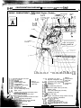
Partial BACKUP
Service Manual
LA-SER
TALON
GROUP/SECTION INDEX
NOOAA-
Electrical .....................................................
:
0
Fusible Link, Fuse and IOD or
Storage Connector Location.. ...................
Inspection Terminal Location ......................
Grounding Location .......................................
1993
Relay Location .................................................
Volume-2
Electrical
Sensor Location ..............................................
Control Unit Location
Solenoid, Solenoid Valve Location .............
FOREWORD
This Service Manual has been prepared with the
latest service information available at the time of
publication. It is subdivided into various group
categories and each section contains diagnosis,
disassembly, repair, and installation procedures
along with complete specifications and tightening
references. Use of this manual will aid in properly
performing any servicing necessary to maintain or
restore the high levels of performance and reliability
designed into these outstanding vehicles.
Diode Location .................................................
Junction Block .................................................
Centralized Junction ....................... ..j ............
Harness Connector Inspection ....................
... ,,
Trou bleshootilng ...............................................
This BACKUP DSM manual IS to be used ONLY as a BACKUP. Please DO NOT REDISTRIBUTE
WHOLE SECTIONS. This BACKUP was sold to you under the fact that YOU do indeed OWN
a GENUINE DSM MANUAL. It CANNOT BE considered a REPLACEMENT (Unless ‘/Our OWnal
manual was lost or destroyed.)
Configuration Diagrams ................................
Please See README.N or README.HTML for additional Information.
Circuit.Diagrams .............................................
Thank you. G~mm~emymanual@hotma~l.com
Engine Electrical .............................................
Chassis Electrical ............................................
1, CHRYSLER
w CORPORA’TION
Chrysler Corporation reserves the right to make changes in design or to
make addltlons to or improvements in Its products without imposing
any obllgatlons upon itself to Install them on its products previously
manufactured.
0 1992 Mitsubishi Motors Corporation
Printed in U.S.A.
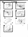
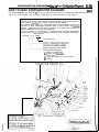
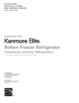
RELAY LOCAT. N
RELAY LOCATION
Name
Symbol
Name
..,. I,,
ABS motor relay
I
B
I Headlight relay
ABS power relay
I
1
1 Heater relay
ABS valve relay
I
B
1 Intermittent wiper relay (rear wiper)
Automatic seat belt motor relay
I J
Blower motor High relay
I
H
Condenser fan motor High-Low select relay
Symbol
1 Intermittent wiper relay (windshield wiper)
1 Magnet clutch relay
~
I
i
1
k
-I --t
C
Power window relay
c
Radiator fan motor relay
Dome light relay
J
Starter relay
Door lock relay
D
Taillight relay
Fog light relay
A
Transistor relay
G
Generator relay
A
Upper beam relay
D
Condenser fan motor relay
’
‘.
A
NOTE
The “Name” column is arranged in alphabetical order.
Engine compartment
Interior
4q
t&
n-
6
motor relay
\
18A0734
--‘;’
8-8
RELAY LOCATJOW
-(built-in columti switchj
WA0732
Blower motor High relay
1
16A1322
I
8-9
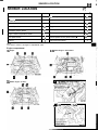
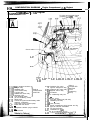
SENSOR LOCATION
SENSOR LOCATION
Name
(/
*
”
.
.
Name
Symbol
:
Symbol
Air inlet sensor
I
ISC motor position sensor
C
Air therm0 sensor
I
Intake air temperature sensor
A
Barometric pressure sensor
A
Knock sensor
G
Camshaft position sensor
D
Oxygen sensor
E
Crankshaft position sensor
D
Rear speed sensor
L
Engine coolant temperature sensor
F
Throttle position sensor
Front speed sensor
J
Vehicle-speed sensor (Reed switch) -
G-sensor
K
Volume air flow sensor
H
A
NOTE
The “Name” column is arranged in alphabetical order.
Engine compartment
1.8L Engine
2.OL DOHC Engine <Non-Turbo>
ZOL DOHC Engine <Turbo>
Volume air flow sens
temperature sensor
and barometric
~2.OL DOHC Engine <Turbc
pressure sensor) \
B
I;‘t.
‘I
i0A0127
1
‘i
8-10
SENSOR LOCATION
- ISC motor positio
2.OL DOHC Engine <Non-Turbo>
r
16AOl326
8-11
SENSOR LOCATION .
6FUO853
Interior
Vehicle speed sensor
(Reed switch)
16AO72B
16AO736
’
I
I
8-12
SENSOR LOCATION
-8173
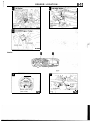
CONTROL UNIT LOCATION
CONTROL UNIT LOCATION
Name
Symbol
4-speed automatic transaxle control module
D
Air conditioning control unit
B
Anti-lock brake control unit
G
Automatic seat belt control unit
F
Door lock control unit
C
Engine control module
E
Auto-cruise control unit
A
I
NOTE
“Name” column is arranged in alphabetical order.
The
Interior
=tz3zzz
_ 1 c&r01 unit
1 Ym,p==L
19AO790
Blower motor
I IlQd
*
Door lock
control
unit
16A0735
4-speed
automatid
’
lltransaxle control module
/
--.
16Al-t’lAfi
\
’ 19AO729
I
Engine
-+--,control
module
MA0784
. ._
8-14
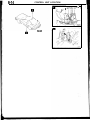
CONTROL UNIT LOCATION
(
P
rh
16A1323
Automatic seat *
belt control unit
r
SOLENOID, SOLENOID VALVE LQCATIQN
84
.’
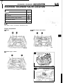
SOLENOID, SOLENOID VALVE LOCATION
Name
Symbol
4-speed automatic transaxle control solenoid
valve
A
EGR solenoid
B
Evaporative emission purge solenoid
.b
“’ I’
B, C
Fuel pressure solenoid
C
Turbocharger waste gate solenoid
C
L
NOT t
The “Name” column is arranged in alphabetical order.
.’
Engine compartment
1.8L Engine
2.OL DOHC Engine <Non-Turbo>
2.OL DOHC Engine <Turbo>
.
I
I .8L Engine
Evaporative emission
8-16
SOLENOID, SOLENOID VALVE LOCATION/DIODE LOCATION
2.OL DOHC <Turbo>
OlAO503
DIODE LOCATION
<Interior-Rear section>
I
Name
1 Symbol 1
1 Diode (for ABS circuit)
Diode (for door ajar-warning cikzuit) ”
B
NOTE
The “Name” column is arranged in alphabetical order
16A1323
CONFIGURATION
DIAGRAMS
CONTENTS
Dash Panel ......................................................
44
NOWA-
Engine Compartment
<2.OL DOHC Engine (Turbo)> ..................... 40
Engine and Transaxle <1.8L Engine> ........ 42
How to Read Configuration Diagrams.. ...... 36
Engine and Transaxle
<2.OL DOHC Engine> ....................................
43
instrument Panel and Floor Console .......... 47
Engine Compartment <1.8L Engine> ......... 36
Interior .............................................................
Engine Compartment
<2.OL DOHC Engine (Non-Turbo)> ............. 38
Overall Configuration Diagram ..................... 34
48
8-34
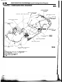
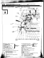
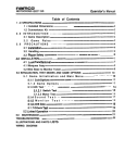
CONFIGURATION DIAGRAMS - Overall Configuration Diagram
OVERALL CONFIGURATION DIAGRAM
NOSVB--
License plate light
wiring harness”3
ABS wiring harness’*
I
Instrument panel wiring harness
/
Lrftgate wiring harness
k kense plate light
3 wiring harness’4
Console wiring harness
Control wiring harness
\
\ /’
I
I
/
ABS sensor
wiring harness’*
Fuel wrring harness <FWD>
Body wiring harness
Battery cable assembly
\
Engrne room wrring harness
NOTE
(1) Thus illustration shows only the major wrnng harness
l l indrcates also equipped at the right side.
‘2 indicates vehicles with ABS.
l 3 indicates PLYMOUTH Laser.
‘4 indicates EAGLE Talon.
16A1334
CONFIGURATION DIAGRAMS - How,,to Read Chnfi~ufatich Dizigtims
8-35
HOW TO READ CONFIGURATION DIAGRAMS
NOWCAI
The wiring diagrams are prepared rn such a way that the arrangement of connectors for each vehicle, and the
routing of each harness, can be easily understood for each individual wiring section.
Indicates the connector number.
The connector number used is the same number as that used for circuit diagrams;
these numbers facllttate the location of the connector positions.
The alphabet letter used as the prefix represents the wiring section in which that
connector is used; subsequent numerals make up the number that Indicates
particular characteristics of that individual connector. As a general rule, numbers are
assigned clockwise around the wiring diagram.
Note that, if there IS a concentration of connectors with the same form (same
number of pins). the connnectors’ colors are noted in order to facilitate identification.
TT ’
Example: A-l 2 (Black)
Connector color
Symbol indicating wiring section
location of the connector
A : Engine compartment
B : Engine and transaxle
C: Dash panel
D: Instrument panel and floor console
E : Interior
E-05
E-06
E-07
E-08
E-09 E-lOE-1
1 E-12
E-19
/E-20
-E-22*8
Indicates ground pornr.
1
E-43
&,
& &glE-38
E:36
E-34
\
8-36
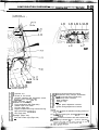
CONFIGURATION DIAGRAMS - Engine Compartment <1.8L Engine>
ENGINE COMPARl -MEN T 4.8L Engine>
To engine and transaxle Ground
cable
(connector svmbol a)
Connector
symbol
I
,,,l
1
To engine and transaxle
(connector symbol q iJ,
Ground cable -
A-47
A-477-l
A-43 A - 42
\I\\\\\
A-41 A-40 A-39 A-38 A-37 A-36 A-35
A-45
A-01X
A-02X
A-03X
A-04X
A-05X
A-06X
A-07X
A-08
A-09
_ _A-1U
A-l 1
A-l 2
A-13
A-l 4
A-15
A4 6
IOD or storage connector
Taillight relay
Headlight relay
Refer to
Power window relay
CENTRALIZED
Fog light relay
JUNCTION
Radiator fan motor relay
Generator relay
/
Dual pressure switch
(for air conditioning circuit)
Wiper motor
Control wiring harness and battery cable
assembly combination
Auto-cruise control vacuum pump
Brake fluid level sensor
Evaporative emission purge solenoid
EGR solenoid
Refer to
A-l 7X Condenser fan motor
CENTRALIZED
high-low changeover relay
JUNCTION
A-l 8X Condenser fan motor relay (for air
A-l 9X Magnetic clutch relay
conditioning
I circuit)
A-20X Condenser
A-21
A-22 ) Air conditioning relay box
A-23
A-24 Washer motor
A-25
Front side marker light (Left side)
Headliaht (Left side)
A-26
A-27
Horn (Left
side)
A-28 I
A-29
Engine compartment wiring harness and fog
light sub harness combination
A-30
Fog light (Left side)
A-31
Condenser fan motor
1.
A-32 (for air cond!tronrng circuit)
Front comblnatron light (Left aid&’ ‘I :- ’
-
To dash panel
(connector symbol q )
\
,
1 A-l 7X
A-:2
\ A-&X
A-\53
A-,54
A-14
4 A-2A-221
A-57
A-‘1 6
.(A-27
\
A-29
36A0270
To engine and transaxle
(connector symbol @I)
/
I
1
i
A-33
A-34 A-35 Volume air flow sensor
A-36 Automatic transaxle fluid temperature sensor
A-37
Kickdown servo switch <A/T>
A-38 Pulse generator <A/T>
A-39 Radiator fan assembly
A-40
Front combination light (Right side)
A-4 1
Radiator water level switch
A-42
Fog light (Right side)
A-43
Engine compartment wiring harness and fog
light sub harness combinatron
A-44
A-45 1 Horn (Right side)
A-46 Headlight (Right side)
A-47
Front side marker light (Right side)
A-48 -
,..,*
A-49
A-50
A-51
A-52
A-53
A-54
A-55
A-56
A-57
Control wiring harness and engine
I compartment
wiring harness combination
Fuel pump check connector
Noise condenser
Defogger relay
Ignition timing adjustment connector
Remarks
(1) The mark * shows the standard mounting position of
wirina harness.
(2) For &tails concerning the ground point (example: 0 ),
refer to P.8-4.
(3) *-” means that the connector with code-number is not
used.
(4) IOD : Ignition Off Draw
., ., .- ..,.a.,., . . .
..‘.
S-38
CONFlGURATlONm~ DIAGRAMS -
Engine Compartment <2.OL DOHC Engine (Non-Tub)>
ENGINE COMPARTMENT <2.OL DOHC Engine (Non-Turbo)>
To engine
and transaxle
(connector symbol a)
A-01X
A-d7X
A-08”’
A-99 A-q8”
A-10\
A-; 1
Ground
cable
A;12
A-51\
cable
To engine and transaxle
(connector symbol q I)
IL
A-47----+%&/-
A-46 A
A-44
A-45
A-01X
A-02X
A-03X
A-04X
A-05X
A-06X
A-07X
A-08
A-43
IOD or storage connector
Talllight relay
Headlight relay
Refer to
Power window relay
CENTRALIZED
Fog light relay
JUNCTION
Radiator fan motor relay
Generator relay
Dual pressure switch
(for air conditioning circuit)
A-09
Wiper motor
._
A-10
Control, I wiring harness and battery cable
assemoly combrnatron
A-11
Auto-cruise control vacuum pump
-12
I
Brake fluid level sensor
A-42
A-41
II \\\
A-40 A-39 A-38 A-37 A-36
A-34
Refer to
A-l 7X Condenser fan motor
CENTRALIZED
high-low changeover relay
JUNCTION
A-l 8X Condenser fan motor relay (for air
A-l 9X Magnetic clutch relay
conditioning
A-20X Condenser
circuit)
A-21 I
Air conditioning relay box
A-22
A-23
ABS front speed sensor (Left side)
A-24 Washer motor
A-25
Front side marker light (Left side)
A-26
Headlight (Left side)
A-27
A-28 t Horn (Left side)
A-29 Engine compartment wiring- harness and fog
light sub harness combrnatron
Fog light (Left side)
Condenser fan motor
(for air conditioning circuit)
Front combination light (Left skit&-,~:~.~~-i.-~~
CONFIGURATION DIAGRAMS -
To dash panel
(connector symbol
q
8-39
Engine Comparbnant -G.OL DOHC Engine (Non-Twbo)>
)
A-52
A-53
A-54
A-14
A-56
I A-31
A-23
A-57
A-‘1 6
36AO271
&,\&---A-24
IA-27
+-’ \
\
A-29
‘A-28
1 \ \ 36A027’
A-32
A-31
A-30
_ To engine and transaxle
(connector symbol q )
A-33
A-34 1 Hydraulic unit
A-35
Volume air flow sensor
A-36
Automatic transaxle fluid temperature sensor
A-37
Kickdown servo switch <A/D
A-38 Pulse generator <A/T>
A-39 Radiator fan assembly
A-40
Front combination light (Right side)
A-4 1
Radiator water level switch
A-42
Fog light (Right side)
A-43
Engine compartment wiring harness and fog
light sub harness combination
A-44
A-45 I Horn (Right side)
A-46 Headlight (Right side)
A-47
Front side marker light (Right side)
A-40
-
A-49
A-50
A-51
A-52
A-53
A-54
A-55
A-56
A-57
Control wiring harness and engine
I ABS
compartment wiring harness combination
front speed sensor (Right side)
Fuel pump check connector
Noise condenser
Defogger relay
Engine speed adjustment connector
Ignition timing adjustment connector
Remarks
(1) The mark * shows the standard mounting positron of
wirina harness
(2) For &tails concerning the ground point (example: 0 ),
refer to P.8-4.
(3) ‘I-” means that the connector with code-number is not
usea.
(4) The wiring indicated by the l I symbol is applicable to
vehicles with ABS and the wiring indicated by the ‘?
symbol is applicable to vehicles without ABS.
8-40
CONFIGURATION DIAGRAMS -
Engine Compartment -Q.OL DOHC Engine fh’bb)>’
L
ENGINE COMPARTMENT <2.OL DOHC Engine (Turbo)>
To engrne and transaxle
(connector symbol q )
A-09 A-08” A-10 \ A - l ?
A-01X
I
A-51
q
A-08’2
\
\
Ground
cable
,
1 A-.12
A-49
A-50
2round
engine and transaxle
(connector symbol q )
A--Jd
A-45 A-43 A-42 A-41
A-01X IOD or storage connector
A-02X Tarllrght relay
A-03X Headlight relay
Refer to
A-04X Power window relay
CENTRALIZED
A-05X Fog light relay
JUNCTION
A-06X Radiator fan motor relay
A-07X Generator relay
A-08
Dual pressure switch
(for air conditioning circuit)
A-09
Wiper motor
I .e
A- I u
Control wiring .harness
and battery cable
.
assemory comornatron
A-l,,1
Auto-cruise control vacuum pump
A-%? ” Brake fluid level sensor
l$$ ,:r.CVontrol wiring harness and solenoid valve
1,i,l.l!..
ji’ ‘i‘harn&x
assembly combination
!d,
$jp{a;i~e emission purge solenoid
&:q@uie solenoid valve
A
30 A-39 A-38 A-37 A-36 A-35=
A-34
Refer to
A-l 7X Condenser fan motor
CENTRALIZED
high-low changeover relay
JUNCTION
A-18X ~ang~e~P,e~:Ua:,hmrc$~ relay (for air
A-l 9X
conditioning
A-20X Condenser
circuit)
A-2 1
Air conditioning relay box
A-22 I
A-23 ABS front speed sensor (Left side)
A-24 Washer motor
Front side marker light (Left side)
A-25
Headlight (Left side)
A-26
- A-2 /
Horn (Left side)
A-28 I
Engine compartment wiring harness and fog
A-29
light sub harness combination
A-30 Fog light.(Left side)
Condenser fan motor
A-31
,(for air cond.itioning,circu,it) ,
A-32 .-!Front comblnatron Ilght (Lett side)
CONFIGURATION DIAGRAMS
g/49:
- Engine &hq&&t’ i=2.0i-DOHC Engirie’ (Turf&>
L
To dash panel
(connector symbol
q
) . A . _,,
A-14
A-131 A-15A-!6
A-52
A-53
A-54
A-55
A-57
A-56.
36AO272
.A-24
A-25
A-26
I \ \ 36A0272
A-32
A-31
A-30
L To engine and transaxle
(connector symbol q )
A-33
A-34 I Hydraulic unit
A-35
Volume air flow sensor
A-36
Automatic transaxle fluid temperature sensor
A-37
Kickdown servo switch <A/T>
A-30
Pulse generator <A/T>
Radiator fan assembly
A-39
A-40
Front combination light (Right srde)
. A-41
Radiator water level switch
A-42
Fog light (Right side)
A-43
Engrne compartment wrring harness and fog
ltght sub harness combinatton
i
A-44
A-45 I Horn (Right side)
A-46 Headlight (Right side)
A-47
Front side marker light (Right side)
A-48
Turbocharger waste gate solenoid
A-49
Control wiring harness and engine
A-50 I compartment wiring harness combination
A-51
ABS front speed sensor (Right side)
Fuel pump check connector
A-52
A-53 Noise condenser
A-54 Defogger relay
A-55 Resistor
A-56
Engine speed adjustment connector
A-57
Ignition timing adjustment connector
Remarks
(1) The mark * shows the standard mounting position of
wiring harness.
(2) For details concernrng the ground point (example: 0 ),
refer to P.8-4.
(3) The winng Indicated by the l l symbol is applicable to
vehicles with ABS and the wiring indicated by the. l 2
symbol is applicable to vehicles without ABS.
(4) IOD : lgnrtlon O f f D r a w
. .
“i8#o;
..
: --., ‘;J
.,%,,
I,.a-?
::
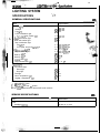
.LIGHTING SYSf@l ‘A Spekficatiailb
,, ,
LIGHTING SYSTEM
”
“),y ??
SPECIFICATIONS
Nmm-
GENERAL SPECIFICATIONS
Items
Specifications
Exterior lights
Headlight
Fog lrght
Front combination light
;. Turn-signal and position ltght
,-Front side marker light
Rear side marker light
Rear combination light
Tail light”
Turn-signal, stop and tall light”
“$$$$urn-signal I;ght’Z
:/
W
w
65/55
25
C P 24/2.2
CP 3
CP 3
C P 32/2 (2057)”
C P 32/2 (2057)”
CP 32 (1 156)‘*
C P 32/2 (2057)**
W 2 7 ”
CP 21’2
w 5
W 27 or 5’3
‘Stop and tail light”*
Back-up light”
Back-up Irght*z
License plate light
High-mounted stop light
nterjor lights
Front dome light
Dome light
Stop light
Foot light
Glove compartment light
Luggage compartment light
W
W
w
w
w
, r $$p$$:
$> ~T;$$
./ +,
.: .,,,
:$,:
,I
8
8
3.4
3.4
5
NOTE
1. ‘1 PLYMOUTH Laser
‘2 EAGLE Talon
$: ‘3 : Vehrcles with rear air spoiler
4. The values in parentheses denote SAE trade numbers.
SERVICE SPECIFICATIONS
I
Items
Limit
Headlight Intensity
NlMlC.’ ,,
Specifications
20,000 cd or more
Y
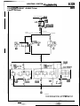
TROUBLESHOOTING
EKFUSIBLE
--I-
H.EADLlGHT
IRCUIT DIAGRAM
Vehicles without daytime running light
c------------
IFF-&IN
. I
11 C-67
dI
C-44
L2
94
EBI
Lx
%
06,
__-_-----
I
lx
c
ITCH
4
InI
C-06
8-229
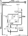
LIGHTING SYSTEM - Troubleshootin@
STOP LIGHT CIRCUIT <EAGLE Talon>
No8lHHn
CIRCUIT DIAGRAM
SUB FUSIBLE LINK@
!s
&I 1 C-42
I
B
J/B
0
15A
‘7 c-50
F
z
d WITHOUT
WITH
AUTO-CRUISE CONTROL
AUTO-CRUISE CONTROL
\
]
L
I
$9
m
I
___---em-
2 E-29
G E-27
'
i
L--
.--&,3
.
E-37
m
Remark
.Xindicates vehicles wlth rear spoiler
8-230
LIGHTING SYSTEM - Service Adjustment Procedures
SERVICE ADJUSTMENT PROCEDURES
NOBIIAF
HEADLIGHT AIMING
PRE-AIMING
Unit B :
Must be used 3’7
at front tire
’
;
’
1
Caltbration fixture
2 . T h u m b adjusttng s c r e w s
3 Level
vial
4
Floor level offset dial
5 Horizontal dial knob
6 Vertical dial knob
7 Almer l e v e l v i a l
8 Level vial bubble
9 Top port hole
10
Vtewing port
INSTRUCTIONS
1. Test dimmer switch operation.
2. Observe operation of high beam light mounted in instrument
cluster.
3. inspect for badly rusted or faulty headlight assemblies. These
conditions must be corrected before a satisfactory adjustment can be made.
4. Place vehicle on a level floor.
5. Bounce front suspension through three (3) oscillations by
applying body weight to hood or bumper.
6. Inspect tire inflation.
7. Rock vehicle sideways to allow vehicle to assume its normal
position.
8. If fuel tank is not full, place a weight in trunk of vehicle to
simulate weight of a full tank [3 kg (6.5 Ibs.) per gallon].
9. There should be no other load in the vehicle other than driver
or substituted weight of approximately 70 kg (150 Ibs.)
placed in driver’s position.
10. Thoroughly clean headlight lenses.
VERTICAL ADJUSTING
Insert the screwdriver into the vertical adjusting hole, and turn
it clockwrse or counterclockwise to bring the bubble of the
vertical angle gauge to the center.
NOTE
The beam angle will change about O”19’ with one mark.
Gear (B)
\
Siopper
I
“0” mark
Gear (A)
/
Hbzzontal adjuszng
hole
-:...z!!%w+
/ . . , ..i,::
HORIZONTAL ADJUSTING
1. After pulling out the stopper upward, press gear (B)
forward to disengage it from gear (A).
2. Insert the screwdriver into the horizontal adjusting hole,
and adjust the horizontal angle.
3. After adjustment, align the “0” mark of gear (B) to the
center line, and press in the stopper for locking.
NOTE
The beam angle will change about 0’36’ with one mark.
LIGHTING SYSTEM - Service Adiustment Procedures
8-231
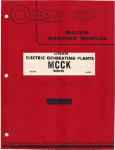
AIMING WITH SCREEN HEADLIGHT AIM PREPARATION
1
Measure the center of the headlight bulb as shown 1~ ihe
illustration.
2
Place vehicle on a known level floor 3m (9.8 feet) from aiming screen or light colored wall. Four lines of adhesive
tape or like are required on screen or wall:
(1) Position a vertical tape so that it is aligned with the vehicle center line.
(2) Position a horizontal tape with reference to center line
of headlight bulb.
(3) Position a vertical tape on the screen with reference to
the center line of each of headlights bulb.
89 (3.5)
P-44
mm (in.)
16A1440
I s creen
I
I
Height of headlight
bulb centers
Vertical center
line ahead of
VISUAL HEADLIGHT ADJUSTMENT
1. A properly aimed lower beam will appear on the airning
screen 3m (9.8 feet) in front of the vehicle. The shaded
area as shown in the illustration indicates high intensity
zone.
2. Adjust low beam of headlights to match the low beam pattern of the right and left headlights.
** Caution
When adjusting one headlight, the other headlight should
be turned off if possible. If this is not possible, do not cover
the other headlight for more than three minutes while it iS
turned on. Otherwise, heat from the bulb may warp the
headlight lens.**
High intensity
zone
16Al441
Vertical Adjusting
1.
2.
Check the position of the level bubble to confirm that it is
within the range as shown in the illustration.
Confirm that the beam irradiated on the screen is the same
as the specified beam pattern.
If it is not the same, adjust the vertical angle with the vertical adjusting screw so that it becomes the specified beam
pattern.
NOTE
If the visual headlight adjustment at low beam is made, the
adjustment at high beam is not necessary.
TSB 26-06-94
Publication NV!
Nqv. 11,1994
8-232
LIGHTING SYSTEM - Service Adjustment Proced&es
LUMINOUS INTENSITY MEASUREMENT
Measure the luminous intensity of headlights with a photometer
in accordance with the instruction manual prepared by the
manufacturer of the photometer and make sure that the
luminous intensity is within the following limit.
Limit: 20,000 cd or more
NOTE
(1) When measuring the luminous intensity of headlight, keep
the engine at 2,000 rpm and have the battery charged.
(21 If there are specific regulations for luminous intensity of
headlights in the region where the vehicle is operated; make
sure that the intensity conforms to the requirements of such
regulations.
I I
FOG LIGHT AIMING
NOBIIEA
1. Place vehicle on a known level floor 7.6 m (25 feet) from
aiming screen or light colored wall.
2. Use adjusting screw to adjust the top end of high intensity
zone to dimension A.
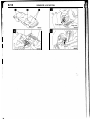
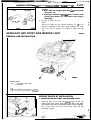
HEADLIGHT BULB REPLACEMENT
1
Pull out the socket cover.
2. Remove the valve mounting spring, and pull the valve out
toward you together with the connector.
3. Disconnect the bulb from the connector.
16Al43!
&& i....
L’ ::, ..,. ~..-i-,.,,i,~.~~s:~.;;i~;
-;*.j
LIGHTING SYSTEM
Good
.‘.
*I
is-
,‘.
---p
- service Adjustment ~ures/Headliiht and Fmnt side Marker mht
8-233
-:
Caution
1. Never hold the halogen light bulb with a bare hand,
dirty glove, etc.
2. if the glass surface is dirly, ba sure to clean it with
alcohol, paint thinner, etc., and install it after drying it
thoroughly.
No good
4. Be sure to attach the cap.
NOTE
Be sure to install the cap securely because, if it IS not, an
insecure installation could cause such problems as clouding of the lens, or intrusion of moisture to inside the light
unit
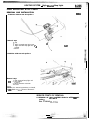
HEADLIGHT AND FRONT SIDE MARKER LIGHT
i
f
NO9UA.Q
REMOVAL AND INSTALLATION
i
19Ao919
Removal steps
l + 1. Front side marker light
2. Headlight
NOTE
(1) Reverse the removal procedures to reinstall.
(2) l
4: Refer to “Service Points of Installation”
/ I
SERVICE POINTS OF INSTALLATION
1. INSTALLATION OF FRONT SIDE MARKER LIGHT
Insert the boss of the front side marker light into the clip
areas of the front fender, and insert the ribs of the front
side marker light into the mounting holes on the headlight
side. Then, mount the front side marker light with the
mounting screws.
,
\
LIGHTING SYSTEM, - ,Rear Combination Light
8-234
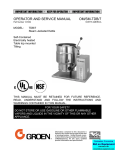
REAR COMBINATION LIGHT
NOEIMAK
REMOVAL AND INSTALLATION
<EAGLE Talon>
10A0927
<PLYMOUTH Laser>
+*
+*
l
Removal steps
1. Back-up light
2. License Dlate liclht
3. Rear panel garnish
4. Lid C (Lid D when the right
rear combination light is removed or
installed)
4 5. Rear combination light
WA0920
NOTE
(1) Reverse the removal procedures to relnstall.
(2) ** : Refer to “Servtce Points of Removal”.
(3) l +: Refer to “Service Points of Installation”.
SERVICE POINTS OF REMOVAL
1. REMOVAL OF BACK-UP LIGHT
Refer to GROUP 23 - Garnishes.
3. REMOVAL OF REAR PANEL GARNISH
Refer to GROUP 23 - Garnishes.
SERVICE POINTS OF INSTALLATION
/
,.4 !
. ..,.,, . z. I/
/
6
----_I
5. INSTALLATION OF REAR COMBINATION LIGHT
Mount ther,elar c@yb,i,nation light by tightening the,nuts
..i
,_ _. ,_.,. -. in
illusmted.
~-- the saq.u&$e
,I2 &&pp,~~~
i’ -..
-
_, ._./
LIGHTING SYSTEM - High Mounted Stop Light
HIGH MOUNTED STOP LIGHT
REMOVAL AND INSTALLATION
NOBIKAK
<Vehicles without rear air spoiler>
Removal steps
1. Clip
2. High mounted stop light cover
3. High mounted stop light lens ant 4J
bracket
Gasket
Y
T
16.40815
\
\
4.
‘1
1
<Vehicles with rear air spoiler>
3
Removal steps
1. High mounted stop light unit
*I)
2. Liftgate trim
3. Wiring harness connector
Socket
\JOTE
Reverse the removal procedures to reinstall,
2) +I) : Refer to “Servie Points of Removal”.
4.
1)
SERVICE POINTS OF REMOVAL
2. REMOVAL OF LIFTGATE TRIM <Vehicles with rear air
spoiler >
Refer to GROUP 23-Trims.