1
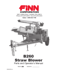
9281 LeSaint Drive • Fairfield, Ohio 45014 Phone (513) 874-2818 • Fax (513) 874-2914 Sales: 1-800-543-7166 Activate Your Warranty By Registering TODAY!!! B-260 Straw Blower Parts and Operator’s Manual Model MM LBB260-MM Serial No. ___________ NOTES ACTIVATE YOUR FINN EQUIPMENT WARRANTY IMPORTANT INFORMATION ON ACTIVATING YOUR FINN EQUIPMENT WARRANTY!!! IT IS IMPERATIVE THAT YOU, THE PURCHASER, COMPLETE THE FOLLOWING STEP IN ORDER TO ACTIVATE THE FINN CORPORATION LIMITED WARRANTY. COMPLETE THE EQUIPMENT REGISTRATION FORM AND MAIL TO THE FINN CORPORATION. IF FINN CORPORATION DOES NOT HAVE YOUR COMPLETED REGISTRATION FORM ON FILE, YOUR WARRANTY CLAIM WILL BE DENIED. Once your FINN equipment has been registered, your FINN Limited Warranty will be activated per the warranty statement on the next page. <<What should you do if you need repairs or parts under Warranty?>> 1. NOTIFY FINN CORPORATION OF THE FAILURE OF MATERIAL OR WORKMANSHIP 1-800-543-7166 Extension (246) [email protected] 2. AFTER YOU OR YOUR SERVICE DEALER NOTIFY FINN, FINN WILL: VERIFY THAT WE HAVE YOUR REGISTRATION ON FILE VERIFY THAT THE WARRANTY PERIOD IS IN EFFECT VERIFY THAT THE RELATED PART(S) ARE INCLUDED IN THE SCOPE OF WARRANTY (PENDING FINN’S INSPECTION OF DEFECTIVE PARTS) SEND YOU REPLACEMENT PART(S) AND A WARRANTY INFORMATION PACKET REQUEST YOU FOLLOW ALL INSTRUCTIONS AS NOTED IN THE PACKET ▪ Completely fill out the Parts Tag. ▪ Attach the Parts Tag to the defective part(s). ▪ Return the part(s) and the completed Warranty Claim Form to FINN Corporation using the return shipping label. (Within 2 weeks) ▪ Tape the Orange identifier sheet, marked with the W/RMA number, on the outside of the box in which you are shipping the defective part(s). Warranty period: Hydroseeders & Straw Blowers 2 years or 2000 hrs which ever comes 1 st All other equipment 1 year or 1200 hrs which ever comes 1st OUR WARRANTY TO YOU: Finn Corporation warrants to you, the original purchaser, for use (or rental to others for use) all new construction machinery, parts and attachments (except those referred to herein) that are manufactured by Finn to be free from defects in material and workmanship for a period noted above. Replacement parts provided under the terms of this warranty are warranted for the remainder of the warranty period applicable to the product to which parts are installed, as if parts were original components of the product. WHAT FINN WILL DO: Upon notification of Finn concerning a failure of material or workmanship in accordance with the above stated Warranty, Finn Corporation will: x Verify claim falls within the valid warranty time frame. x Verify the product and equipment has been registered with Finn in order to be eligible for warranty coverage. x Upon affirmation of warranty period and registration, Finn will send to you a new or repaired replacement part(s), whichever Finn elects and a “Warranty Claim Information packet” containing instructions for processing the warranty claim. x Evaluate the part when defective part is returned. Note: Failure to return defective part within two weeks will result in an invoice being sent to the customer. In addition, if damage to a part is determined not to be covered under the warranty, the customer will be billed. x Reconcile costs with customer for parts and shipping, as determined by our inspection of failed parts, and confirmation of warranty coverage, per the terms of this warranty. x Correction of nonconformities, in the manner provided above, shall constitute fulfillment of all liabilities of Finn Corporation. WHAT YOU MUST DO TO OBTAIN WARRANTY SERVICE: x As the purchaser covered under the above limited warranty you must REGISTER the equipment with Finn FAILURE TO REGISTER WILL VOID THE WARRANTY. x Claim Number: Notify the warranty Dept. same day or next day of any intent to do warranty work and obtain a “Warranty Claim Number,” x All warranty labor must be pre-approved by providing Finn with an estimate of labor costs. Once approved, Finn will issue you a Work Authorization Number, prior to work being performed.(EXCEPTION: Unless the labor is per the Labor Allowance Schedule or less) x The labor costs reimbursement will be based on the Labor Allowance Schedule established by Finn and where not applicable, on a reasonable number of hours as determined by Finn. x Notify Finn Corporation of any failure of material or workmanship as described under this warranty. ¾ Web notification: [email protected] ¾ Phone 1-800-543-7166 extension 246 x Complete the required steps in the “Warranty Claim Information packet” (which Finn will send you) and return the defective part(s) as directed in the packet to Finn Corporation. x Should the failed part, be a hydraulic component, Finn may send you an “Oil Analysis Kit,” requesting that a sample of oil from the hydraulic system be taken, and mail it to a lab. Follow the instruction sheet, on how to use your Finn Oil Analysis Kit that comes with the Kit. Failure to comply when requested will void the warranty. WHAT THE WARRANTY DOES NOT COVER: 1. Normal wear parts and Allied Equipment or trade accessories not manufactured by it, such as but not limited to items such as various filters, fluids, brakes, clutch linings, belts, hoses, light bulbs, mechanical seal, over center clutches, tires, ignitions, starters, batteries, magnetos, carburetors, engines and labor, or like or unlike equipment or accessories. (Such being subject to the warranty, if any, provided by their respective manufacture). 2. Secondhand, used, altered, or rebuilt machines or parts. 3. Defects, malfunctions or failures resulting from accidents, abuse, misuse, improper servicing, or neglect of required operational guidelines and maintenance service, as outlined in the Finn Corporation’s Operators Manual(s). Commercial Limited Warranty Effective 4/1/2011 4. The warranty shall be null and void to the extent any defect or failure of the products warranted arises out of or is caused by accessories or component parts not manufactured or supplied by Finn Corporation, whether same are supplied by purchaser, dealers, or any other party. 5. This Warranty does NOT cover any costs associated with transporting the equipment for warranty service, such as mileage, fuel, or man hours; such is the responsibility of the equipment owner. 6. Dealers & Customers are responsible to follow all guidelines related to Seasonal & Long Term Storage of Equipment, as advised in operation & equipment manuals. i.e. Finn, Engine, Clutch, Pump, Motor, etc. Equipment failures caused by neglect of these guidelines are not warrantable. THIS IS THE ONLY EXPRESS WARRANTY ON OUR PRODUCTS: We neither assume nor authorize anyone to assume for us any other express warranty. The Distributor/Dealer has no authority to make any representation or promise on behalf of Finn Corporation or to modify the terms or limitations of this warranty in any way. THIS WARRANTY THEREFORE SHALL BE IN LIEU OF ALL OTHER WARRANTIES, EXPRESS OR IMPLIED, INCLUDING, BUT NOT LIMITED TO, ANY IMPLIED WARRANTY OF MERCHANTABILITY OR FITNESS FOR A PARTICULAR PURPOSE. LIMITATIONS ON OUR RESPONSIBILITY WITH RESPECT TO PRODUCTS PURCHASED: THE REMEDIES OF THE USER SET FORTH HEREIN ARE EXCLUSIVE, WITHOUT REGARD TO WHETHER ANY DEFECT WAS DISCOVERABLE OR LATENT AT THE TIME OF DELIVERY OF THE PRODUCT TO THE PURCHASER. ALL WARRANTY REPAIR MUST BE DONE BY A FINN AUTHORIZED SERVICE PROVIDER OR AUTHORIZED REPAIR SHOP OF FINN’S CHOICE. TRANSPORTATION, HAULING, STORAGE, OR OTHER SIMILAR COSTS ARE NOT PART OF FINN’S OBLIGATION UNDER THE LIMITED WARRANTIES AND IS THE RESPONSIBILITY OF THE EQUIPMENT OWNER. THE ESSENTIAL PURPOSE of this exclusive remedy shall be to provide the original purchaser with repair or replacement of parts that prove to be defective within the period and under the conditions previously set forth. This exclusive remedy shall not have failed of its essential purpose (as that term is used in the Uniform Commercial Code) provided Finn remains willing to repair or replace defective parts within a commercially reasonable time after it obtains actual knowledge of the existence of a particular defect. IN NO EVENT shall Finn be liable for any special, consequential, incidental or indirect damages, including lost profits or lost commercial opportunities, with respect to the sale of the above warranted product or anything done in connection therewith, or for property damage sustained by a person claiming to be a third party beneficiary of a surviving warranty under the law of any jurisdiction. NOTICE: FINN CORPORATION URGES the use of only Finn corporation supplied parts and attachments to assure proper performance and safe operation of Finn corporation equipment. Insist on parts and attachments manufactured or supplied by Finn corporation when you purchase, repair or replace your Finn equipment and attachments. Because Finn corporation cannot assure that parts and attachments not manufactured or supplied by Finn meet Finn corporation's quality standards, specifications, or operating requirements, our warranty is not effective to the extent any failure of or defect in a Finn corporation product arises from or is caused by parts, attachments or components not originating with Finn corporation. Use of Finn corporation equipment with parts and attachments not manufactured or supplied by Finn could result in personal injury. INDEX Safety First . . . . . . . . . . . . . . . . . . . . . . . . . . . . . . . . . . . . . . . . . . . . . . . . . 1 Straw Blower Safety Summary Section . . . . . . . . . . . . . . . . . . . . . . . . . 2–4 Introduction. . . . . . . . . . . . . . . . . . . . . . . . . . . . . . . . . . . . . . . . . . . . . . . . . 5 Definition of Mulching. . . . . . . . . . . . . . . . . . . . . . . . . . . . . . . . . . . . . . . . . 5 The FINN B260 Straw Blower and How It Works . . . . . . . . . . . . . . . . . . . 5 Towing Vehicle . . . . . . . . . . . . . . . . . . . . . . . . . . . . . . . . . . . . . . . . . . . . . . 5 Loading Bales . . . . . . . . . . . . . . . . . . . . . . . . . . . . . . . . . . . . . . . . . . . . . . 5 Attachment (50 ft Extension For Discharge Spout) . . . . . . . . . . . . . . . . . . 6 Positioning the Feed Chute Extension. . . . . . . . . . . . . . . . . . . . . . . . . . . . 6 Pre-Start Check . . . . . . . . . . . . . . . . . . . . . . . . . . . . . . . . . . . . . . . . . . . . . 6 Equipment Check. . . . . . . . . . . . . . . . . . . . . . . . . . . . . . . . . . . . . . . . . . . . 7 Starting the Engine. . . . . . . . . . . . . . . . . . . . . . . . . . . . . . . . . . . . . . . . . . . 8 PowerView . . . . . . . . . . . . . . . . . . . . . . . . . . . . . . . . . . . . . . . . . . . . . . 9–11 Faceplate . . . . . . . . . . . . . . . . . . . . . . . . . . . . . . . . . . . . . . . . . . . . . . . 9 PowerView Operation . . . . . . . . . . . . . . . . . . . . . . . . . . . . . . . . . 10–11 PowerView Menus (First Time Start-Up) . . . . . . . . . . . . . . . . . . . 10 Stored Fault Codes . . . . . . . . . . . . . . . . . . . . . . . . . . . . . . . . 10–11 Crew Members and Their Duties . . . . . . . . . . . . . . . . . . . . . . . . . . . . . . . 11 Feeding the Mulch . . . . . . . . . . . . . . . . . . . . . . . . . . . . . . . . . . . . . . . . . . 12 Distributing the Mulch. . . . . . . . . . . . . . . . . . . . . . . . . . . . . . . . . . . . . . . . 12 Smoothing Out Mulch Patterns . . . . . . . . . . . . . . . . . . . . . . . . . . . . . . . . 13 Clogging of the Mulch Blowing System . . . . . . . . . . . . . . . . . . . . . . . . . . 13 Hydraulic System . . . . . . . . . . . . . . . . . . . . . . . . . . . . . . . . . . . . . . . . . . . 14 Troubleshooting the Hydraulic System . . . . . . . . . . . . . . . . . . . . . . . . . . 15 Cleaning and Maintenance . . . . . . . . . . . . . . . . . . . . . . . . . . . . . . . . 15–19 After First 100 Hours of Operation. . . . . . . . . . . . . . . . . . . . . . . . . . . 15 Daily Clean-up Maintenance . . . . . . . . . . . . . . . . . . . . . . . . . . . . 15–16 Weekly Maintenance . . . . . . . . . . . . . . . . . . . . . . . . . . . . . . . . . . . . . 16 Adjusting the Drive Belt . . . . . . . . . . . . . . . . . . . . . . . . . . . . . . . . 16–17 Adjusting the Feed Chain. . . . . . . . . . . . . . . . . . . . . . . . . . . . . . . . . . 18 Clutch Care and Maintenance . . . . . . . . . . . . . . . . . . . . . . . . . . . . . . 19 Lubrication Chart . . . . . . . . . . . . . . . . . . . . . . . . . . . . . . . . . . . . . . . . 20–21 INDEX Parts Manual Section . . . . . . . . . . . . . . . . . . . . . . . . . . . . . . . . . . . . . 22–58 Pictorial Reference. . . . . . . . . . . . . . . . . . . . . . . . . . . . . . . . . . . . . . . . . . 23 Trailer . . . . . . . . . . . . . . . . . . . . . . . . . . . . . . . . . . . . . . . . . . . . . . . . 24–25 Axle Assembly . . . . . . . . . . . . . . . . . . . . . . . . . . . . . . . . . . . . . . . . . . . . . 26 Trailer Wiring . . . . . . . . . . . . . . . . . . . . . . . . . . . . . . . . . . . . . . . . . . . . . . 27 Shredder Box and Blower Housing . . . . . . . . . . . . . . . . . . . . . . . . . . 28–29 Beater Chain Assemblies . . . . . . . . . . . . . . . . . . . . . . . . . . . . . . . . . . 30–31 Power System . . . . . . . . . . . . . . . . . . . . . . . . . . . . . . . . . . . . . . . . . . 32–33 Engine and Radiator . . . . . . . . . . . . . . . . . . . . . . . . . . . . . . . . . . . . . 34–35 Power Take-Off Assembly . . . . . . . . . . . . . . . . . . . . . . . . . . . . . . . . . 36–37 Hydraulic System . . . . . . . . . . . . . . . . . . . . . . . . . . . . . . . . . . . . . . . . 38–39 Air Intake and Exhaust System . . . . . . . . . . . . . . . . . . . . . . . . . . . . . 40–41 Control Box Wiring Diagram . . . . . . . . . . . . . . . . . . . . . . . . . . . . . . . 42–43 Engine Wiring Diagram . . . . . . . . . . . . . . . . . . . . . . . . . . . . . . . . . . . 44–45 Feed Chute Assembly . . . . . . . . . . . . . . . . . . . . . . . . . . . . . . . . . . . . 46–47 Feeder Roll Assembly . . . . . . . . . . . . . . . . . . . . . . . . . . . . . . . . . . . . 48–49 Operator Platform. . . . . . . . . . . . . . . . . . . . . . . . . . . . . . . . . . . . . . . . 50–51 Discharge Head . . . . . . . . . . . . . . . . . . . . . . . . . . . . . . . . . . . . . . . . . 52–53 Seat Assembly . . . . . . . . . . . . . . . . . . . . . . . . . . . . . . . . . . . . . . . . . . 54–55 Decal Locations . . . . . . . . . . . . . . . . . . . . . . . . . . . . . . . . . . . . . . . . . 56–57 Recommended Spare Parts, Tool Kit and Repair Kits. . . . . . . . . . . . . . . 58 SAFETY FIRST With any piece of equipment, new or used, the most important part of its operation is SAFETY! FINN Corporation encourages you and your employees to familiarize yourselves with your new equipment and stresses safe operation. The first five pages of this manual are a summary of the main safety aspects associated with this unit. Be sure to read and understand completely before operating the machine. The symbols below are used throughout the operation and maintenance sections of this manual to call attention to safety procedures. DANGER Indicates a hazardous situation which, if not avoided, will result in death or serious injury. WARNING Indicates a hazardous situation which, if not avoided, could result in death or serious injury. CAUTION Indicates a hazardous situation which, if not avoided, could result in minor or moderate injury. NOTICE Indicates practices that are not related to personal injury. NOTE: Gives helpful information CALIFORNIA CALIFORNIA Proposition 65 Warning Proposition 65 Warning The engine exhaust and some of its constituents are known to the State of California to cause cancer, birth defects, and other reproductive harm. Battery posts, terminals, and related accessories contain lead and lead compounds, chemicals known to the State of California to cause cancer and reproductive harm. Wash hands after handling. 1 STRAW BLOWER SAFETY SUMMARY SECTION It is important that all operators of this machine are familiar with all safety aspects mentioned below, and have read the entire Operator’s Manual before operating the machine. Always keep a copy of this manual with the machine. It is the responsibility of the operator of the machine to fully understand this safety sheet. Remember that YOU are the key to safety. Good safety practices protect not only you, but also the people working with and around you. Keep in mind that this safety sheet is written for this type of machine only. Practice all other usual and customary safe working precautions. Above all, remember that safety is up to you. The FINN STRAW BLOWER is intended to be used as an applicator of vegetative hay or straw mulches onto the seedbed. Its use with other products or for other applications must be by approval of the product’s manufacturer. If there are any questions, contact FINN Corporation at 1-800-543-7166. I. PRE-START EQUIPMENT CHECK (equipment check is to be made with the engine OFF): 1. Check hitch and hitch bolts, safety chains, lights, brakes, and breakaway switch. Verify that the hitch ball is the correct size for the coupler. 2. Check that all guard railing is in place and secure. 3. Verify that all guards are in place. 4. By carefully looking in the shredder box, inspect the shredder box for foreign objects. 5. With the ignition switch ON, verify that the signal horn is operating correctly. 6. Make sure no one is working on or inside the machine. Give a visual and audible signal that all is clear before starting the engine. II. MACHINE OPERATION: 1. 2. Always wear safety goggles when operating or feeding the machine. Other safety attire, such as safety shoes, ear protection, gloves, hard hats, dust masks, etc., should be worn as required by warning decals on machine, operator’s manuals, or jobsite requirements. Remove rings, watches, etc. Avoid wearing loose-fitting clothing that may get caught in rotating machinery. Do not operate the machine without all guards in place. 3. Make sure the discharge spray area is clear of all persons, animals, etc. 4. The driver of the carrying or towing vehicle is responsible for the safety of the operator(s) and feeder(s) of the machine. Make sure the driver is aware of and avoids all possible hazards to the operator(s) on the machine, such as tree limbs, low power lines, etc. Vehicles on which equipment is mounted or towed must be started or stopped gradually. Avoid abrupt starts and stops. Never operate on a slope or a hill that may endanger the operator(s). All personnel should review and be familiar with start/stop signals between the driver and operator(s) before operation of the equipment. 5. Operator(s) of equipment should never ride on machine at speeds greater than 5 MPH (8 km/h). 6. Never operate machine in an enclosed area without venting the exhaust of both the equipment and the vehicle on which the equipment is mounted or towed. Deadly carbon monoxide fumes can accumulate. 7. Never operate this or any other machinery when fatigued, tired, under the influence of alcohol, illegal drugs, or medication. You must be in good physical condition and mentally alert to operate this machine. 8. Never modify the machine. Never remove any part of the machine (except for service and then reinstall before operating). 9. Use proper means for mounting and dismounting of machine. Never mount or dismount a moving machine. 10. Do not aim discharge at people, animals, etc. Only aim the discharge at the intended seedbed. 2 11. Do not open any doors or access panels while machine is in operation. Severe injury may result from rotating parts. 12. Do not attempt to pull anything out of the feed chute or shredder box when machine is in operation. Shut down the engine using (Occupational Health and Safety Administration (OSHA) lockout/tagout procedure 29 CFR 1910.147), before removing any foreign objects. Give a visual and audible signal that all is clear before restarting the machine. III. MAINTENANCE: 1. Before servicing the machine, turn off engine and allow all moving parts to stop. Disconnect the battery cables to prevent accidental starting of the machine. Tag the engine operating area to show that the machine is being serviced. Use lockout/ tagout procedure (29 CFR 1910.147). 2. On trailer units, perform general maintenance such as checking the safety chains, hitch, hitch bolts, tires, and brakes. Repair or replace if worn or broken. Never operate machine on improperly inflated or damaged tires. Always use a safety cage or cable restraints when reinflating a repaired tire. 3. Battery maintenance. Lead-acid batteries contain sulfuric acid, that will damage eyes or skin on contact. Always wear a face shield to avoid getting acid in the eyes. If acid contacts eyes, flush immediately with clean water and get medical attention. Wear rubber gloves and protective clothing to keep acid off skin. Lead-acid batteries produce flammable and explosive gases. Keep arcs, sparks, flames, and lighted tobacco away. 4. Filling of fuel. Never fill the fuel tank while the engine is running, while smoking, or when near an open flame. Never smoke while handling fuel or working on the fuel system. The fumes in an empty fuel container are explosive. Never cut or weld on fuel lines, tanks, or containers. Move at least 10 feet (3 meters) away from fueling point before starting engine. Wipe off any spilled fuel and let dry before starting engine IMPORTANT: Be careful not to allow fuel, lubricant, hydraulic fluid, or cooling fluids to penetrate into the ground or be discharged into the water system. Collect all used fluids and dispose of them properly. 5. It is recommended that only authorized, genuine FINN replacement parts be used on the machine. 6. Make certain that all decals on the machine are maintained in good legible condition. Replacement decals are available through FINN Corporation by specifying the part number shown in the lower righthand corner of the decal. See page 4 for the current set of safety decals mounted on the unit. See Parts Manual for the location and quantity of all decals on this unit. 3 CURRENT SET OF SAFETY DECALS #!54)/. 7!2.).' (9$2!5,)#3934%-).3425#4)/.3 #HECKOILLEVELWEEKLY!DDOILWHENLEVEL GOESDOWNTOFIRSTRINGONFILLERSCREEN "52.(!:!2$ (OTEXHAUST 3TAYBACK &AILURETOCOMPLYCOULDRESULTIN DEATHORSERIOUSINJURY #HANGEFILTERONOILTANKEVERYOPERATING HOURS5SEAMICRONFILTERELEMENTONLY #!54)/. #HANGEHYDRAULICOILWHENTHECOLORTURNS MILKYWHITE#OLORCHANGEISDUETOWATER GETTINGINTOHYDRAULICSYSTEM .%7#,54#().&/2-!4)/. !NEWCLUTCHMAYREQUIRESEVERALADJUSTMENTSUNTILFRICTION SURFACESAREWORNIN $/./4LETCLUTCHSLIP4HISWILLGLAZEANDRUINFRICTION SURFACES 7HENPROPERLYADJUSTEDAHEAVYPRESSUREISREQUIREDATLEVER TOMOVETHROWOUTLINKAGETOOVERCENTERORLOCKED POSITION !LWAYSMAINTAINPROPERADJUSTMENT #ONSULTOPERATIONSMANUALFORADJUSTMENTINSTRUCTIONS &AILURETOCOMPLYMAYRESULTINEQUIPMENTDAMAGE +EEPALLFITTINGSANDHOSESTIGHTANDLEAK FREE +EEPSYSTEMCLEANATALLTIMES $/./4STARTORRUNENGINEWITHOUT HYDRAULICOILINRESERVOIR0ERMANENTPUMP DAMAGEWILLOCCUR 7!2.).' 0. #HECKANDCLEANSUCTIONSTRAINERONCEA YEARORWHENOILISCHANGED &!,,(!:!2$ $/./4RIDEONEQUIPMENTWHEN MOVINGATSPEEDSINEXCESSOF -0(KMH (9$2!5,)# &,5)$/.,9 3EE/PERATORS -ANUALFORTYPE &AILURETOCOMPLYCOULDRESULTIN DEATHORSERIOUSINJURY 0. 0. 7!2.).' &,9).'/"*%#43 7EARPROPEREYEPROTECTIONWHENFEEDINGMACHINE &AILURETOCOMPLYCOULDRESULTINDEATHORSERIOUSINJURY 7!2.).' 3%6%2(!:!2$ +EEPHANDSCLEAR 2OTATINGFANANDGEARS $/./4OPERATEWITHOUTGUARDSORDOORSINPLACE 3HUTOFFENGINEDISCONNECTBATTERYANDALLOWALLMOVINGPARTSTOSTOP BEFORESERVICING &,9).'$%"2)3 7EAREYEPROTECTIONAROUNDEQUIPMENT &AILURETOCOMPLYCOULDRESULTINDEATHORSERIOUSINJURY 7!2.).' 0. "52.(!:!2$ #OOLINGSYSTEMISUNDERPRESSURE !LLOWSYSTEMTOCOOLBEFOREHANDLING 2EMOVERADIATORCAPSLOWLY 7EARAPPROPRIATESAFETYGEAR &AILURETOCOMPLYCOULDRESULTINDEATHORSERIOUSINJURY 0. 7!2.).' 0. 7!2.).' 25.!7!96%()#,%(!:!2$ !LWAYSINSPECTTOWVEHICLEANDEQUIPMENTHITCHBEFORETOWING 4IGHTENALLHITCHBOLTSANDPROPERLYCONNECTWIRINGANDSAFETYCHAINS "2%!+!7!937)4#( $/./4USEFORPARKING !TTACHCABLETOTOWINGVEHICLEWITHENOUGHSLACKFORTURNING %NGINEBATTERYONTRAILERMUSTBECHARGEDANDHOOKEDUPFORPROPERBREAKAWAYFUNCTION 3!&%49#(!).).34!,,!4)/. "OTHTHESINGLEANDDOUBLECHAINSMUSTBECROSSEDUNDERTONGUE4HEYMUSTBEORIENTEDINSUCHAMANNERASTOPREVENTTONGUEFROMDROPPING TOGROUNDINEVENTOFFAILURETOHITCHCOUPLERORBALL#HAINSMUSTBECONNECTEDTOTOWINGVEHICLESOSLACKFOREACHLENGTHOFCHAINBETWEEN TRAILERANDTOWINGVEHICLEISTHESAMEANDMUSTHAVENOMORESLACKWHENINUSETHANNECESSARYTOPERMITPROPERTURNINGOFVEHICLES&ORWARD ENDOFCHAINMUSTBEATTACHEDTOTOWINGVEHICLENOTTOBALLBUTTOHITCHOROTHERFRAMEMEMBER#HAINMUSTBELOOPEDAROUNDMEMBERAND HOOKEDBACKINTOITSELF &AILURETOCOMPLYCOULDRESULTINDEATHORSERIOUSINJURY 0. 4 $ONOTOPERATEWITHOUT GUARDSINPLACE &AILURETOCOMPLYCOULD RESULTINDEATHOR SERIOUSINJURY 7!2.).' 2!$)!4/2(!.$,).').3425#4)/.3 5SEASOLUTIONOFWATERANDANTIFREEZE5SINGANTIFREEZEWILLRESULTINENGINEDAMAGE #HECKANDREPLENISHWATERPRIORTOUSE-OREWATERWILLBECONSUMEDWHENOPERATINGINHOTCONDITIONS )FOVERFLOWPIPEBEGINSEMITTINGVAPORCHECKANDREPLENISHWATER 2EMOVEANDCLEANSCREENWHENDIRTY #HECKANDCLEANFINSPERIODICALLY#LOGGEDFINSWILLINCREASEWATERCONSUMPTION 0ROTECTRADIATORFROMFERTILIZERCORROSIONBYWASHINGRADIATORCOREWITHWATER 0. 7EARPROPEREYEAND EARPROTECTIONWHEN OPERATINGMACHINE &AILURETOCOMPLYCOULD RESULTINDEATHOR SERIOUSINJURY 0. OPERATION AND MAINTENANCE MANUAL FOR THE FINN B260 STRAW BLOWER INTRODUCTION This manual is designed for step-by-step instructions of the operation, care, and maintenance of the B-260 Straw Blower and, in addition, it contains illustrations and descriptions of a complete list of parts and components for easy identification. For best results and to ensure longer life of the equipment, please follow the instructions carefully. For your safety, read the entire manual before operation of this unit. DEFINITION OF MULCHING Mulching is the process whereby a vegetative mulch, such as hay or straw, sometimes excelsior, or other wood product or other vegetative material, is spread on previously seeded areas to promote germination, while providing temporary erosion control. THE FINN B260 STRAW BLOWER AND HOW IT WORKS The FINN B260 Straw Blower will apply vegetative mulch at a fast and uniform rate, utilizing a minimum amount of manpower. The baled vegetative mulch material is placed on the feed chute and separated by the bale feeder as he feeds these bales into the shredder housing. In the shredder housing, a combination of beater chains and air currents separates the mulch into individual fibers that are drawn into the blower housing and blown through the discharge assembly onto the seedbed. TOWING VEHICLE The truck used to tow the FINN Straw Blower should have a bed large enough to carry the quantity of mulch needed for economical operation. If the Straw Blower is going to be used on rough, hilly terrain, a truck with a two-speed axle is suggested. This will supply the necessary slow speed required for careful, uniform application. The truck must be equipped with a ball or pintle hitch with a large enough rating to tow the Straw Blower. Use a 2-5/16 in. (58 mm) ball, rated at least 7,500 lb (3,401 kg). The tow truck must be able to support 750 lb (340 kg) down on its hitch. There must be provisions for the safety chains to be attached. The hitch should be mounted as near the end of the truck bed as possible. LOADING BALES Load the bales of mulch on the truck bed with binder twine or wire on top rather than on the side. This makes it easier to grab the bales while the Straw Blower is in operation. Place the first layer of bales lengthwise on the truck. The second layer of bales should be placed crosswise. Alternate successive layers lengthwise and crosswise in order to secure the load. Leave enough room at the rear of the truck bed for the bale handler to stand. 5 ATTACHMENT: 50 ft (15 m) EXTENSION FOR DISCHARGE SPOUT The collapsible tube, when secured to the spout of the adapter, will extend the length of the discharge spout by 50 ft (15 m). When this tube is attached, mulch material must be pushed farther through the tube before being discharged. Therefore, it is important to keep the air pressure as high as possible. This can be done by feeding not more than two bales per minute of good, bright material. If using lower quality material, the feeding must be done at a slower rate. NOTE: Keep the tube as straight as possible. Do not feed mulch until tube is filled with air. POSITIONING THE FEED CHUTE EXTENSION The feed chute extension should extend at least 18 in. (45 cm) over the rear edge of the truck bed. To achieve this, use the following: 1. Unhook the discharge spout holddown and fold it down to the horizontal position. 2. Move the discharge tube to the side. 3. Move the feed chute extension down to the feed position. If the extension is short of the edge of the truck bed, move it to the rear set of mounting holes. 4. Next, adjust the feed chute so that it is 6 to 12 in. (15 to 30 cm) higher than the bed of the truck. 5. Be sure that, when turning the truck, the payload does not come in contact with the feed chute. PRE-START CHECK Safety check to ensure operator safety: 1. Check the bolts on the hitch and safety chains, the brakes, and the trailer lights. 2. With ignition ON, check the amber safety light. 3. Check that the signal horn operates properly. 4. Ensure that all guards are in place. 5. Verify that the red safety light is not illuminated. Check the safety switches if the red safety light is illuminated. 6 EQUIPMENT CHECK WARNING Equipment check should be made with the engine OFF and all rotating parts stopped. Failure to comply could result in death or serious injury. 1. Tool Kit - make sure that it contains all prescribed items (see tool kit list, page 58 in parts manual). 2. Lubricate equipment. Use handgun only (see lube chart on pages 20 and 21). 3. Check engine oil and fuel and fill or change if necessary. Refer to the engine manual for proper oil and fuel. Check hydraulic oil level and fill as required. (See hydraulic system for oil spec.) 4. Inspect air cleaner for dust and dirt. If necessary, clean the filter by using the following steps: A. Knock the loose particles from element. B. Wash with water and detergent. C. Rinse and allow to dry. Do not force dry, do not use compressed air or heat. 5. Check belts for proper tightness. Belts are in proper adjustment when 8 lb (3.6 kg) pressure in the center of the belt, produces 3/8 in. (1 cm) depression. 6. Engage and disengage clutch to determine if it snaps in and out of engagement. 7. Check the radiator liquid level and fill if necessary (protected to -34˚F (-37˚C) when shipped). 8. Check shredder box for foreign objects that could damage the equipment or injure workers. 9. Check beater chains and their mounting pins for damage or wear. Replace if necessary. 7 STARTING THE ENGINE CAUTION See safety section of the manual (pages 2 through 4) before operating the machine. Failure to comply could result in minor to moderate personal injury. Failure to comply could also result in product or property damage. 1. Make sure that the clutch is disengaged, and that the power feed handle is in the OFF position. 2. Turn ignition switch to the START position. If engine does not start within 10 seconds, turn the key back to the OFF position and wait at least 30 seconds before trying again. NOTE: This engine has a safety system that will shut the engine off if the engine oil pressure drops below 7 psi (48 kPa), or if the water temperature reaches 239˚F (115˚C). 3. Allow the engine to warm up at high idle for 3 to 5 minutes. 4. The engine information display will show the current engine conditions. The display can be customized to show different engine parameters, such as rpm, hours, volts, coolant temperature, etc. See POWERVIEW on pages 9 through 11. 5. With the engine still idling, engage the clutch slowly. Move the throttle to the wide-open position and let the governor control the engine speed. The governed speed of the engine on the FINN Straw Blower should be 2,550 to 2,600 rpm under a load. CAUTION Before engaging the clutch, make sure that the discharge tube is under control and is pointed in the proper direction. Failure to comply could result in minor to moderate personal injury. Failure to comply could also result in product or property damage. NOTICE After the first 4 to 8 hours of operation, the drive belt should be checked and adjusted (see pages 16 and 17). The clutch should also be checked and adjusted (see page 19). 8 POWERVIEW The PowerView is a multifunctional tool that enables the operator to view many different engine parameters and service codes. A graphical back-lit LCD screen can display either a single parameter or a quadrant display showing four parameters simultaneously. Diagnostic capabilities include fault codes with text translation for the most common fault conditions. The following relative engine parameters can be displayed in either English or Metric units, as well as in Spanish, French, or German: AMBER WARNING LED • Engine rpm RED SHUTDOWN DERATE LED • Engine Hours • System Voltage • % Engine Load at Current rpm • Coolant Temperature BEZEL DISPLAY MENU KEY ENTER KEY • Oil Pressure • Throttle Position • Active Service Codes LEFT ARROW KEY (Scroll Up) RIGHT ARROW KEY (Scroll Down) Figure 1 - Faceplate Features FACEPLATE The keypad on the PowerView is a capacitive touch-sensing system. There are no mechanical switches that can stick or wear out. It can be operated in extreme temperatures, while wearing gloves, and is impervious to ice, snow, mud, grease, etc. When the key is touched, feedback is provided by flashing on the screen. The keys on the keypad perform the following functions (refer to Figure 1): Menu Key The Menu Key is used to either enter or exit the menu screens. Left Arrow Key The Left Arrow Key is used to scroll through the screen, either moving the parameter selection toward the left or upward. Right Arrow Key The Right Arrow Key is used to scroll through the screen, either moving the parameter selection toward the right or downward. Enter Key The Enter Key is used to select the parameter that is highlighted on the screen. 9 POWERVIEW OPERATION PowerView Menus (First Time Start-Up) 1. Once the engine has been started and the keyswitch is turned to RUN, the Engine rpm parameter (ENG rpm) is displayed. See Figure 2. 0 2000 4000 1800 RPM ENG RPM COOL TEMP 2. To toggle through the various engine parameters, touch either the Left or Right Arrow Key. 3. To switch to the 4-Up Display, touch the Menu Key to display the first seven items of the Main Menu. See Figure 3. MENU KEY Figure 2 - 1-Up Display 4. Since the first menu item listed is GO TO 4-UP DISPLAY, touch the Enter Key to select the 4-Up Display. See Figures 3 and 4. GO TO 4-UP DISPLAY ENGINE CONFGURATION STORED FAULT CODES ADJUST BACKLIGHT ADJUST CONTRAST SELECT UNITS SETUP 1-UP DISPLAY ENTER KEY Figure 3 - Main Menu 0 RPM ENG RPM 0 PSI OIL PRES 46F COOL TEMP 12.3 VDC BAT VOLT MENU KEY Figure 4 - 4-Up Display Stored Fault Codes The PowerView Display will store any fault codes generated by the engine, along with a text description. To access these fault codes: 1. Touch the Menu Key to display the Main Menu. 2. Using the Right Arrow Key, toggle down the list until STORED FAULT CODES is highlighted. See Figure 5. 3. Touch the Enter Key to view any stored fault codes. The display will respond by presenting a REQUESTING FAULT CODES message, while the system retrieves the codes. See Figure 6. GO TO 4-UP DISPLAY ENGINE CONFGURATION STORED FAULT CODES ADJUST BACKLIGHT ADJUST CONTRAST SELECT UNITS SETUP 1-UP DISPLAY ENTER KEY Figure 5 - Main Menu 4. Once the stored fault codes have been retrieved, the initial code will be displayed along with a text description. See Figure 7. 10 5. If the word MORE appears at the bottom of the display, this indicates that there are additional fault codes being stored. Use the Right Arrow Key to advance to the next code. 6. As long as the arrow in the display appears to the right of the word MORE as you advance through the fault codes, this means there are more codes available for viewing. When the arrow in the display shifts to the left of the word MORE, this is an indication that you have accessed the final fault code being stored. At this point you can touch the Left Arrow Key to review the fault codes, or touch the Menu Key to return to the Main Menu. REQUESTING FAULT CODES ENTER KEY Figure 6 - Access Stored Fault Codes SHUTDOWN WARNING SPN110 FMI10 HIGH COOLANT TEMP MORE MENU KEY MORE This Means There Are More Stored Fault Codes MORE This Means There Are No More Stored Fault Codes HIDE TO REVIEW STORED FAULT CODES Figure 7 - Stored Fault Codes CREW MEMBERS AND THEIR DUTIES 1. The Operator controls the placement of the mulch on the seedbed by moving the discharge assembly. He also controls the movement of the towing truck along the seedbed by using a predetermined set of signals for the signal horn. 2. The Bale Handlers operate from the truck bed and supply the power feed assembly with bales of mulch material. They cut and dispose of bale twine or wire and keep the power feed chute full of material with no gaps so there will be no interruption in distribution of mulch to the seedbed. 3. The Truck Driver follows the directions of the operator for the movement of the towing truck. The truck driver should be cautious in starting or stopping the truck so that the crew members are not thrown off balance. 11 FEEDING THE MULCH The power feed assembly of the FINN Straw Blower has been designed to give fast, uniform mechanical feeding. The adjustable feeding rate allows the use of various materials, and at the same time obtains maximum production.The power feed assembly is driven by a power feed chain. This allows the mulch material to be fed at an adjustable rate to the separator roll, which drops the bats into the shredder housing. The power feed chain is driven by a hydraulic motor mounted on the top side of the power feed chute. This motor is controlled by the operator at the discharge control station. The power feed control is a lever that, when pulled back from the center position, makes the power feed chain run away from the shredder housing. When pushed forward from the center position, it causes the power feed chain to move toward the shredder housing. Either forward or rearward, the farther the lever is moved, the faster the chain travels. Once a speed has been selected, centering the lever stops the chain. If the lever is returned to its previous position, the chain will move at the previous speed. Through use of the power feed control lever, the operator can momentarily stop the feeding cycle when wet bales are encountered or when it is necessary to stop application because of driveways, bridge abutments, etc. The operator can slow down or speed up the rate of feeding depending on the type of material that is being encountered per bale. To start the power feed, push the control lever slowly until the desired speed is reached. It is necessary for bale handlers to keep the power feed chute completely full at all times in order to get the maximum production rate of the FINN Straw Blower. The operator should have a full stream of mulch coming at all times and should be directing the material to the area being mulched. The operator has complete control of the power feed mechanism by the use of the control lever and can vary the rate of feed instantaneously to fit all conditions. If the bale handlers are unable to keep the feed chute full, the operator should slow the feed down slightly until the bale handlers can keep up. This will allow a more uniform application. If the feed rate is not fast enough for good, bright straw, and the control handle is full forward, move the handle to the right and then forward into the high-speed forward slot. It is suggested that with every truckload of mulch, the power feed tray should be emptied. This will allow the operator to remove any wire or twine from around the feeder roll. Rate of feed should never be set beyond the capacity of the machine so as to compensate for the poor quality of mulch material being used. Failure to comply could result in overloading of the machine, which causes extensive wear and maintenance problems. DISTRIBUTING THE MULCH The Straw Blower should be towed to a point approximately 60 ft (18 m) from the area where mulch is to be applied. The operator elevates the discharge spout about 10 degrees above the plane of the seedbed so that the mulch floats onto the seedbed. NOTE: Do not drive the mulch into the seedbed with air pressure. The higher the tube is held, the more uniform the application will be. A full circle horizontal travel of the discharge spout allows the operator to vary the direction of the discharge spout according to the prevailing winds. The tube should never be directed into the wind, towards any persons, or at the towing vehicle. 12 SMOOTHING OUT MULCH PATTERNS The lower roll assembly in the shredder housing, driven by the blower power band, is equipped with mounting points for eight beater chains and six fingers. For normal straw application, only four to six chains are needed. If you have material coming out in lumps or find it impossible to handle because the mulch is wet or hard, install extra chains in pairs until smoothness of mulch application is reached. CAUTION Be sure beater chains are mounted opposite each other at all times to avoid throwing the blower shaft out of balance. Failure to comply could result in minor to moderate personal injury. Failure to comply could also result in product or property damage. If your equipment is still throwing mulch material out in lumps and does not have a good discharge pattern, move the last beater hub closer to the blower housing, but within the shredder box. CLOGGING OF THE MULCH BLOWING SYSTEM If during operation the machine gets plugged, simply shut off the power feed. If the machine does not clear, disengage clutch and let the machine coast to a stop. Before turning off the engine, the operator can reverse the power feed chain using the control lever. This will unload the power feed chute to facilitate cleaning the machine. DANGER Do not reach into the shredder box or attempt to make any adjustment until the engine and all rotating parts have stopped. Failure to comply WILL result in serious personal injury or death. Four access locations have been provided to allow the removal of any obstructions: 1. The opening into the beater box into which the mulch material is fed. 2. The access door in the shredder housing. 3. The access door into the blower discharge transition. 4. The discharge tube itself. When the obstruction has been removed and access doors closed, the motor can be restarted and mulch application continued. If consistent plugging occurs, it can be caused by one of several reasons: 1. The bale handlers do not feed the bales at a consistent rate and/or do not guide the bales properly onto the power feed mechanism, leaving gaps in the stream of bales or leaving the bats laying flat on the tray. 2. The power band is out of adjustment, causing it to slip. 3. The clutch is out of adjustment and is slipping. 4. Incorrect type or quantity of beater chains are installed. 5. Operator is feeding the mulch material too fast, overloading the shredder housing. 13 HYDRAULIC SYSTEM The hydraulic system on your FINN Straw Blower consists of a pump, reservoir with suction strainer, oil filter, and power feed hydraulic motor with flow control valve set to operate at 2,000 psi (13,790 kPa). The most important maintenance areas are the hydraulic oil and filtration. The reservoir holds 8 gal (30 L) of ISO Grade 46 Hydraulic Oil. Hydraulic oil should be replaced per the lubrication schedule or if the oil becomes milky or smells burnt. The hydraulic-system oil filter cartridge must be replaced with a 5 Micron absolute filter cartridge (FINN part number 023914). The following checks will keep your FINN Straw Blower in proper operating condition: 1. Check oil level once a week. Add additional oil when level goes down below 1-1/2 in. (3.8 cm). 2. Change oil filter on oil tank every 500 hours of operation. 3. Check and clean suction strainer once a year or whenever the oil is changed. 4. Change hydraulic oil whenever the color turns to milky white, (change is caused by water getting into hydraulic system) or if oil smells burnt. 5. Keep all fittings and hoses tight and leak-free. 6. Keep system clean at all times. CAUTION Do not start or run the engine without hydraulic oil in the reservoir or with a closed reservoir ball valve as permanent damage to the hydraulic pump will occur. Failure to comply could result in minor to moderate personal injury. Failure to comply could also result in product or property damage. 14 TROUBLESHOOTING THE HYDRAULIC SYSTEM Symptom Probable Cause Remedy Power feed motor will not run in either direction Plugged suction strainer Clean strainer. Suction line valve closed Open valve. Collapsed suction hose Replace hose. Worn pump Repair or replace. Power feed chain runs unevenly Loose chain Adjust tension on chains. Power feed motor runs in reverse only Flow control stuck or plugged Repair or replace. Flow control cable inoperative Repair cable. CLEANING AND MAINTENANCE WARNING Turn off engine and disconnect battery before servicing equipment. Failure to comply could result in death or serious injury. AFTER FIRST 100 HOURS OF OPERATION 1. Check belt tension on the drive belt. See pages 16 and 17. 2. Check and adjust clutch. See page 19. 3. Torque wheel lugs. Torque again after 7 days. DAILY CLEAN-UP MAINTENANCE Follow this procedure daily to keep the equipment in good operating condition: 1. Check the air cleaner on the engine by removing the element and checking the cleanliness of the element. Check the cleanliness by inserting a light inside the element. If light cannot be seen shining through the element, the element is dirty. Wash it with clean water and detergent; do not use a pressure hose. If you cannot get it clean enough to see light shining through it, the element should be replaced. 2. Clean the radiator and radiator screen with tap water. 3. Check crankcase oil level and add oil if necessary. 4. Check the tension on the power band. There should be a 3/8 in. (1 cm) depression at the center of the band when using 8 lb (3.6 kg) of pressure. Adjust if necessary. 15 5. Clean beater rolls. Make sure to remove all twine, wire, and other foreign objects. 6. Lock the discharge tube (using the holddown strap) into the carrying saddle. 7. Fill the fuel tank. 8. Check hitch bolts, safety chains, and brakes. WEEKLY MAINTENANCE After each 40 hours of operation, follow this procedure: 1. Change the engine oil following the engine manufacturer's recommendations. 2. Change the engine oil filter cartridge with every other oil change. 3. Lubricate bearings with general-purpose chassis lubricant to remove dirt and prevent overheating. 4. Inflate tires to pressure as specified on the tire. 5. Check clutch adjustment to ensure that it snaps in and out of engagement. Refer to the clutch manual for instructions. ADJUSTING THE DRIVE BELT 1. Remove the BELT GUARD to expose the DRIVE BELT. 2. Position a straight edge across the belt, starting from the BLOWER SHAFT SHEAVE and extending across the top of the ENGINE CLUTCH SHEAVE. See Figure 8. 3. Apply 8 lb (3.6 kg) of pressure directly down on the DRIVE BELT (about halfway between the two sheaves). Measure the distance from the bottom of the STRAIGHT EDGE, to the top of the DRIVE BELT. This dimension should be 3/8 in. (1 cm). 4. If the DRIVE BELT requires adjustment, loosen the four bolts that secure the FRONT ENGINE MOUNT and the REAR ENGINE FOOT to the trailer frame. 5. Mark the FRONT and REAR JACKING BOLTS to identify the current positions. 6. To tighten the DRIVE BELT, tighten the REAR JACKING BOLT by turning the bolt clockwise two full turns. 7. To keep the engine in proper alignment, loosen the FRONT JACKING BOLT by turning the bolt counterclockwise two full turns. 8. Check the DRIVE BELT measurement as described in steps 2 and 3. 9. Continue to adjust JACKING BOLTS to obtain the correct measurement. 10. After obtaining the correct measurement, tighten the four bolts that secure the FRONT ENGINE MOUNT and the REAR ENGINE FOOT to the trailer frame. 11. Replace the BELT GUARD. 16 REAR JACKING BOLT FRONT JACKING BOLT TO TIGHTEN TO LOOSEN FRONT ENGINE MOUNT APPLY 8 LBS OF PRESSURE HALFWAY BETWEEN SHEAVES REAR ENGINE FOOT RULER 3/8” STRAIGHT EDGE DRIVE BELT ENGINE CLUTCH SHEAVE BLOWER SHAFT SHEAVE Figure 8 - Adjusting the Drive Belt 17 ADJUSTING THE FEED CHAIN 1. About halfway between the IDLER SPROCKET ASSEMBLY and the DRIVE SHAFT IDLER ASSEMBLY, pull the FEED CHAIN taut and away from the bottom of the FEED CHUTE WELDMENT. At the point where you have pulled the FEED CHAIN away, measure the distance between the top of the FEED CHAIN and the bottom of the FEED CHUTE WELDMENT. This should measure 4-1/2 in. (11.4 cm). See Figure 9. 2. If the FEED CHAIN requires adjustment, loosen the four bolts that secure the IDLER SPROCKET ASSEMBLY to the FEED CHUTE WELDMENT. 3. Adjust the FEED CHAIN by moving the IDLER SPROCKET ASSEMBLY toward the end of the FEED CHUTE until you obtain the measurement provided in step 2. If the 4-1/2 in. (11.4 cm) measurement cannot be obtained by shifting the IDLER SPROCKET ASSEMBLY, remove links from the FEED CHAIN as necessary to obtain the correct adjustment. 4. Tighten the four bolts that secure the IDLER SPROCKET ASSEMBLY to the FEED CHUTE WELDMENT. DIESEL FUEL ONLY FEED CHAIN IDLER SPROCKET ASSEMBLY IDLER SPROCKET ASSEMBLY BOLTS SEE VIEW A VIEW A B260 Straw B lower 4-1/2” FEED CHAIN GUARD IDLER SPROCKET ASSEMBLY FEED CHAIN BOTTOM OF FEED CHUTE WELDMENT PULL FEED CHAIN TAUT Figure 9 - Adjusting the Feed Chain 18 DRIVE SHAFT IDLER SPROCKET ASSEMBLY CLUTCH CARE AND MAINTENANCE This is a short, simple outline of the NACD clutch adjustment and lubrication procedure. When performing maintenance beyond this brief outline, refer to the NACD Care and Operations manual. In order to properly identify parts when ordering replacement parts, always refer to the unit and specification number stamped on the nameplate located on the top-center of the power take-off housing. NOTE: If your Straw Blower is equipped with a NACD clutch, refer to the NACD Power Take-Off Service Manual For 6-1/2 in., 7-1/2 in., 8 in., 10 in. and 11-1/2 in. HE Clutches. LUBRICATION The NACD clutch is equipped with lifetime internal lubrication bearings and should not be lubricated. The operating shaft bearing (located where the drive shaft exits the clutch housing) should, however, be lubricated every 1 to 3 months, depending on usage. The clutch engage lever shaft should be lubricated weekly. ADJUSTMENT If the clutch does not pull, heats, or if the operating lever pops out of engagement, the clutch must be adjusted. To adjust the clutch, remove the nameplate located on the top-center of the power take-off housing. Turn the clutch shaft assembly until the adjusting lock pin can be reached. Disengage the adjusting lock pin and turn the adjusting ring clockwise until the clutch lever requires a distinct pressure to engage (approximately 26 lb of pull). A new clutch generally requires several adjustments until the friction surfaces are worn in. After the clutch is worn in, the adjustment should be checked regularly. CAUTION Do not adjust clutch too tightly. Over tightening can cause component failure. 19 5 8 HYDRAULIC FLUID ONLY HYDRAULIC SYSTEM INSTRUCTIONS 15 7 HYDRAULIC OIL LEVEL AND FILTER 7 POWER FEED SHAFT BEARINGS 14 10 6 DIESEL FUEL ONLY 12 16 4 14 11 1 2 0. 3% 7 26)# %% % +, 9 3 (!.$'5. /.,9 0. % )# 26 3% ),9 $! 9 13 POWER SYSTEM Figure 10 - Lubrication Points 20 BLOWER SHAFT BEARINGS LUBRICATION CHART Ref. No. 1 2 3 4 5 6 7 8 9 10 11 12 13 14 15 16 Location Lubricant Clutch Shaft Bearing CL Check Engine Oil Level MO Clutch Yoke Shaft CL Check Air Cleaner Check Hydraulic Oil Level HO Change Hydraulic Oil and Filter HO Discharge Elbow Bearing CL Rotate Elbow to six or eight different positions Power Feed Shaft Bearings CL Feeder Roll Bearing CL Blower Shaft Bearings CL Check Fuel Tank Level DF Change Engine Oil MO Check Engine Coolant Level AF Check Engine Coolant AF Check Oil Filter Repack Wheel Bearings CL Change Hydraulic Oil Filter HO Check Fuel Filter Frequency Number Weekly Daily Weekly Daily Daily Annually Daily 1 1 2 1 1 1 1 Weekly Weekly Weekly Daily See Engine Manual Daily Seasonally See Engine Manual Seasonally Seasonally Daily 4 1 2 1 1 1 1 1 2 1 2 LUBRICANT OR FLUID USED CL MO AF DF HO Chassis Lubricant Motor Oil - See Engine Manual 50/50 Antifreeze and Water Mixture Diesel Fuel Hydraulic Oil, ISO Grade 46 TIME KEY DAILY (8 hours) WEEKLY (40 hours) SEASONALLY (500 hours) ANNUALLY (2000 hours) SEE ENGINE MANUAL FLUID CAPACITIES Fuel - 27 gal (102 L) Hydraulic Oil - 8 gal (30 L) Engine Coolant - 3.75 gal (14.2 L) 50/50 Mix Only Engine Oil - 14 qts (13.3 L) 21 B260 Straw Blower Parts Manual Model MM 22 WHEN ORDERING PARTS, BE SURE TO STATE SERIAL NUMBER OF MACHINE FINN B260 STRAW BLOWER FEED CHUTE See Pages 48-51 OPERATOR PLATFORM AND DISCHARGE HEAD See Pages 52-57 SHREDDER & BLOWER See Pages 30-33 POWER SYSTEM See Pages 34-47 TRAILER See Pages 26-29 DECAL LOCATIONS RECOMMENDED SPARE PARTS TOOL KIT REPAIR KITS See Pages 58-59 See Page 60 See Page 60 See Page 60 WHEN ORDERING PARTS, BE SURE TO STATE SERIAL NUMBER OF MACHINE 23 1 3 13 5 15 16 17 6 4 2 13 14 18 7 8 20 10 11 9 27 19 12 20 21 22 REF: TRAILER WIRING (SEE PAGE 29) 29 23 28 34 REF: AXLE ASSEMBLY (SEE PAGE 28) 25 32 24 26 37 39 24 38 35 36 30 31 33 WHEN ORDERING PARTS, BE SURE TO STATE SERIAL NUMBER OF MACHINE Ref. No. 1 2 3 4 5 6 7 8 9 10 11 12 13 14 15 16 17 18 19 20 21 22 23 24 25 26 27 28 29 30 31 32 33 34 35 36 37 38 39 Part Number 080043 005134 005135 190033 004888 023485 022588 023592 023938 023922 023923 023591-07 023765 007914 023770-02 022739-04 023770-01 023529-11 023529-10 023742 F60-0015 005545 005138* 005137-A 005437 005436 005137* 005137-A 000489 FW71090* 012979-03 012979-05 F400-0031 011770 012979-01 012979-02 011851* F400-0038 031389 023424* 005016 190029 005017 023762* 075592* TRAILER Description Tow Ring (Standard) Coupler (Optional) 2-5/16 in. Ball (Optional) Safety Chain - 3 ft Length Coupling Link Clevis Grab Hook Frame Jack Dual Jack Mount Dual Jack Arrangement CEQUENT 2k Jack CEQUENT Crank Assembly Connecting Rod Fuel Tank Assembly Fuel Tank Cap Fuel Return Tube Assembly Fuel Level Gauge Fuel Suction Tube Assembly Front Fuel Tank Strap Rear Fuel Tank Support Fuel Tank Mounting Weldment Fender U-Bolt Right Taillight Assembly Lens 3-Bar Light License Light Left Taillight Assembly Lens Static Strip Marker Light Red Battery Cable Black Battery Cable Battery Box Fab Battery Box Red Battery Jumper Black Battery Jumper Battery Battery Box Hold Down Tool Box Breakaway Switch S Hook Chain Snap Hook Trailer Wiring Harness 7-Blade Trailer Plug No. Required 1 1 1 2 2 2 1 1 1 2 1 1 1 1 1 1 1 1 1 1 2 8 1 1 1 1 1 1 1 2 1 1 1 2 1 1 2 1 1 1 2 1-1/2 ft 1 1 1 *NOTE: See Page 27 for Wiring Diagram. WHEN ORDERING PARTS, BE SURE TO STATE SERIAL NUMBER OF MACHINE 25 1 2 4 3 16 15 14 5 13 12 11 7* 6* 10 9 8 *NOTE: ITEM #6 ALSO INCLUDES ITEM #7. AXLE ASSEMBLY Ref. No. Part Number 1 2 3 4 5 6 7 8 9 10 11 12 13 14 15 16 023919 080669 080668 023780 080663 023919-W WL6-80 023919-17 023919-16 023919-15 023919-14 023919-11 023919-10 023919-12 023919-13 023919-7 023919-8 Description No. Required Axle with Spindles, Hubs and Drums Wheel and Tire Assembly Tire Tire Valve Wheel Hub and Drum Assembly Wheel Nut Grease Cap Cotter Pin Spindle Nut Spindle Nut Washer Outer Bearing Drum Inner Bearing Grease Seal Brake Assembly LH Side Brake Assembly RH Side 1 2 1 per 1 per 2 2 8 per 1 per 1 per 1 per 1 per 1 per 1 per 1 per 1 per 1 per axle 1 per axle NOT SHOWN 023919-18 023919-9 26 Rubber Plug Retaining Nut WHEN ORDERING PARTS, BE SURE TO STATE SERIAL NUMBER OF MACHINE 1 per 10 per axle TRAILER PLUG TAIL LIGHTS (BROWN) NOT USED 16 GA. (RED) TO STARTER 16 GA. (YELLOW) TO LEFT TAILLIGHT 16 GA. (GREEN) TO RIGHT TAILLIGHT LEFT TURN (YELLOW) RIGHT TURN (GREEN) 16 GA. (WHITE) TO BRAKE GROUND (WHITE) E) WHIT ( . A 16 G BRAKE TO 16 GA. (WHITE) TO RIGHT BRAKE 16 GA. (BLACK) TO BRAKE ) ACK . (BL E A G 16 RAK TO B T LIGH TAIL T F E TO L 16 GA. (BROWN) TO MARKER LIGHT 16 GA. (BROWN) TO 3-BAR LIGHT 16 GA. (BROWN) FROM 3-BAR LIGHT TO LICENSE LIGHT (RED) ELECTRIC BRAKES (BLACK) (BLACK) 16 GA. (BROWN) 16 GA. (BROWN) TO MARKER LIGHT TO RIGHT TAILLIGHT TRAILER WIRING Part Number 023762 075592 023424 FW71090 005138 005137 005436 005437 Description No. Required Trailer Wiring Harness 7-Blade Trailer Plug Breakaway Switch Marker Light Right Taillight Assembly Left Taillight Assembly License Light 3-Bar Light 1 1 1 2 1 1 1 1 NOTE: See Pages 24-25 for Locations of the above components. WHEN ORDERING PARTS, BE SURE TO STATE SERIAL NUMBER OF MACHINE 27 4 5 REF: BEATER CHAIN ASSEMBLIES (SEE PAGES 32-33) 6 1 7 2 8 14 13 9 3 10 12 15 10 17 16 11 18 25 21 22 26 2 27 28 29 24 23 21 22 19 20 35 34 36 30 37 31 32 33 28 WHEN ORDERING PARTS, BE SURE TO STATE SERIAL NUMBER OF MACHINE SHREDDER BOX AND BLOWER HOUSING Ref. No. 1 2 3 4 5 6 7 8 9 10 11 12 13 14 15 16 17 18 19 20 21 22 23 24 25 26 27 28 29 30 31 32 33 34 35 36 37 Part Number 023418 021511 023632 023311 021512 022159 021361* 021822* 023228* 023334 021365 023752 023627 023583-06 F260-0017 023527 023794-01 004996 023571 023573 023572-09 022202 052436** 052707 023536 060030 011441 023595 023839 060032 190127-32 060305B 023537 160052 023850 160152 007705 Description Blower Shaft End Cover Bearing Blower Cover Weldment Blower Blade Assembly Bushing Key Beater Chain Assembly - 3 Pitch Beater Chain Assembly - 4 Pitch Beater Chain Assembly - 5 Pitch Breaker Collar Blower Shaft Bearing Shield Assembly Blower Housing Rubber Holddown Pad Tube Holddown Holddown Strap Assembly Clutch Handle 1 in. Pipe Plug Shredder Box Weldment Access Door Door Latch Plastic Handle Grip Door Switch Hex Nut Dust Guard Bushing Key Engine Clutch Sheave Drive Belt Blower Shaft Sheave Key Bushing Belt Guard Elbow 90 Degree ST 1/8 15 in. Lg. Grease Hose 1/8 in. Standard Coupling 1/8 in. NPTF Straight Grease Fitting No. Required 1 2 1 1 1 1 1 1 1 3 1 1 1 1 1 1 1 1 1 1 3 3 1 1 1 1 1 1 1 1 1 1 1 1 1 1 1 NOTES: * See Pages 30 though 32 for component breakdown. ** See Pages 44 and 45 for Wiring Diagram WHEN ORDERING PARTS, BE SURE TO STATE SERIAL NUMBER OF MACHINE 29 3 2 3 2 4 4 ITEM #1 (3-PITCH BEATER CHAIN ASSEMBLY) INCLUDES ITEMS #2 - 6. 6 3 ITEM #7 (4-PITCH BEATER CHAIN ASSEMBLY) INCLUDES ITEMS #8 - 12. 3 8 2 4 5 2 10 4 9 4-PITCH BEATER CHAIN ASSEMBLY 12 9 14 11 10 8 15 16 18 15 17 30 16 14 ITEM #13 (5-PITCH BEATER CHAIN ASSEMBLY) INCLUDES ITEMS #14 - 18. WHEN ORDERING PARTS, BE SURE TO STATE SERIAL NUMBER OF MACHINE BEATER CHAIN ASSEMBLIES Ref. No. 1 Part Number 021361 Description Beater Chain Assembly - 3-Pitch No. Required 1 2 020111 Chain - 3-Pitch 4 3 022487 Nut 4 4 020119 Chain Pin 4 5 021363 Bushing 1 6 021555 Beater Hub Weldment 1 7 021822 Beater Chain Assembly - 4-Pitch 1 8 020110 Chain - 4-Pitch 1 9 022487 Nut 2 10 020119 Chain Pin 2 11 021363 Bushing 1 12 021824 Beater Hub Weldment 1 13 023228 Beater Chain Assembly - 5-Pitch 1 14 023363 Chain - 5-Pitch 2 15 022487 Nut 2 16 020119 Chain Pin 2 17 021363 Bushing 1 18 021824 Beater Hub Weldment 1 WHEN ORDERING PARTS, BE SURE TO STATE SERIAL NUMBER OF MACHINE 31 11 REF: AIR INTAKE & EXHAUST SYSTEM (SEE PAGES 42-43) 10 9 8 5 6 13 12 7 4 3 2 1 32 REF: ENGINE & RADIATOR (SEE PAGES 36-37) 15 14 WHEN ORDERING PARTS, BE SURE TO STATE SERIAL NUMBER OF MACHINE POWER SYSTEM Ref. No. Part Number Description No. Required 1 052398-08 Rear Spacer 2 2 006499* Horn 1 3 023924 Air Cleaner Bracket 1 4 F260-0025 Engine Plug Bracket 1 5 JDR517320 Engine Wiring Harness 1 6 F260-0044 Rear Engine Panel 1 7 F260-0006-03 Hinge Spacer 1 8 F260-0006-02 Radiator Cap Cover 1 9 055669 Door Positioning Hinge 1 10 Removed Engine Side Panel N/A 11 F260-0045 Engine Top Cover 1 12 023666 Radiator Chaff Screen 1 13 190087 Chaff Screen Seal 124 in. 14 023667 Chaff Screen Latch 2 15 F260-0042 Radiator Shroud Weldment 1 F260-0042-06 Side Filler Angle 2 * NOTE: See Pages 42-43 for Wiring Diagram. WHEN ORDERING PARTS, BE SURE TO STATE SERIAL NUMBER OF MACHINE 33 25 23 24 20 16 22 19 21 14 18 15 13 11 18 12 16 17 1 3 2 10 8 9 REF: POWER TAKE-OFF ASSEMBLY (SEE PAGES 38-39) 4 5 34 6 7 WHEN ORDERING PARTS, BE SURE TO STATE SERIAL NUMBER OF MACHINE ENGINE AND RADIATOR Ref. No. 1 2 3 4 5 6 7 8 9 10 11 12 13 14 15 16 17 18 19 20 21 22 23 24 25 Part Number 023916 JDRE529643 JDRE5522878 023539 023166 023167 F260-0041 Removed JDRE541420 023685 JDSD443 JDSD284 053105 JD50-0532 022452 Removed Removed 023929 023807 Removed F330-0135 023438 F330-0131 Removed Removed Description 4045T Tier III Engine Assembly Primary Fuel Filter Secondary Fuel Filter Rear Engine Foot Rear Jacking Bolt Front Jacking Bolt Front Engine Mount Air Deflector Oil Filter Hydraulic Pump* Fan Spacer Fan Shroud Fan Radiator Assembly Drain Cock Hose Clamp Lower Radiator Hose Rubber Isolator Radiator Cap Upper Radiator Hose Radiator Support Strap Rubber Shock Mount Rear Radiator Mount Fan Gaurd Mountijng Strap Fan Gaurd No. Required 1 1 1 1 1 1 1 N/A 1 1 1 1 1 1 2 N/A N/A 1 1 N/A 1 1 1 N/A N/A NOTES: * See Pages 38-39 for Hydraulic System Layout. NOT SHOWN JD94100-0256 2.56 in. T-Bar Clamp 6 JDP532949 2.25 in. Silicone Hose 2 JDR128455 Upper Radiator Hose 1 JD32-H Hose Clamp 1 JD50-0073 Upper Radiator Pipe 1 JDP148337 2 in. T-Bolt Clamp 2 JDR135730 2 in. x 2.25 in. x 3 in. Hose Adapter 2 JD50-0265 Lower Radiator Pipe 1 WHEN ORDERING PARTS, BE SURE TO STATE SERIAL NUMBER OF MACHINE 35 36 WHEN ORDERING PARTS, BE SURE TO STATE SERIAL NUMBER OF MACHINE POWER TAKE-OFF ASSEMBLY Ref. No. 1 2 4 7 8 9 10 11 12 13 14 15 17 20 24 25 26 27 28 33 76 77 78 79 109 110 112 113 125 126 127 128 129 132 136 146 148 412 413 414 415 417 418 419 430 431 432 433 434 436 No Number Part Number 012069 012069-1 012069-2 012069-4 012069-7 012069-8 012069-9 012069-10 012069-11 012069-12 012069-13 012069-14 012069-15 012069-17 012069-20 012069-24 012069-25 012069-26 012069-27 012069-28 012069-33 012069-76 012069-77 012069-78 012069-79 012069-109 012069-110 012069-112 012069-113 012069-125 012069-126 012069-127 012069-128 012069-129 012069-132 012069-136 012069-146 012069-148 012069-412 012069-413 012069-414 012069-415 012069-417 012069-418 012069-419 012069-430 012069-431 012069-432 012069-433 012069-434 012069-436 012069-935 Description Power Take-Off Assembly - SAE #4 w/10 in. Clutch Bell Housing Name Plate Bolt Grease Zerk Drive Shaft Main Bearings Bearing Retainer Adjusting Lock Lock Bolt Lock Washer Cross Shaft Woodruff Key Yoke Sub Assembly Shifting Lever Sub Assembly Output Key Pilot Bearing (furnished by customer) Nut Locking Washer Clutch Key Grease Fitting (cross shaft) Cover Plate Machine Screw Headless Set-Screw (Not Shown) Clutch Assembly Clutch Body Facing Plate Pressure Plate Adjusting Ring Release Sleeve Bearing Carrier Release Bearing Internal Snapring External Snapring Sleeve and Bearing Assembly (125-129 and 148) Pressure Plate Assembly (112, 113, and 146) Wear Ring Grease Fitting (in Release Sleeve) Lever Spring Lever Clevis Pin Retaining Ring Lock Bolt Lock Washer Adjustment Lock Link Clevis Pin Retaining Ring Clevis Pin Retaining Spring Release Bearing Drive Ring WHEN ORDERING PARTS, BE SURE TO STATE SERIAL NUMBER OF MACHINE No. Required 1 1 2 1 1 2 1 1 1 1 1 1 1 1 1 1 1 1 2 1 1 1 1 1 1 1 1 1 1 1 1 1 1 1 1 1 1 1 3 3 3 1 1 1 6 3 3 3 3 3 1 37 20 24 28 12 27 22 29 6 23 10 19 19 6 13 7 4 3 9 4 14 16 1 8 25 18 11 2 5 26 21 17 38 WHEN ORDERING PARTS, BE SURE TO STATE SERIAL NUMBER OF MACHINE 15 HYDRAULIC SYSTEM Ref. No. 1 2 3 4 5 6 7 8 9 10 11 12 13 14 15 16 17 18 19 20 21 22 23 24 25 26 27 28 29 Part Number 008690 008691 012044 012086 012087 023612 023614 023731 023618 023621 023810 0023899 023911 023932-01 055229 055233 023120 055359 055383 070408 FW71870 005793 008686 011466 023858 021559 023568 023685 023710 023913 023914 160062 160305 Description Air-Way #6506-8-8 Air-Way #6410-12-8 Pressure Gauge #CF-5000-25 Lenz #A3105-8-10 (Midstate #6400-08-10) Lenz #A3105-12-12 1/2 in. 100R2 Hyd. Hose x 63 in. 90 Degree 3/4 in. 100R4 Hyd. Hose x 34 in. 45 Degree Seal Kit Lenz #3405L-8-8 Lenz #A3405-8-10 1/2 in. 100R2 Hyd. Hose x 67 in. Air-Way #6803-8-8-8 Air-Way #6405-8-12-O 1 in. Hyd. Hose x 41 in. OAL w/ 1 in. Lenz #8-4HB Lenz #A3105-12-08 (Midstate #6400-12-08) Seal Kit Lenz# A3105-8-12 Lenz #A3105-16 (Midstate #6400-16-16) Lenz #APC-10-8 Lenz #3505SW-8 (Midstate #6500-8-8) Hydac Filler/Breather Brand Hydraulic Valve Suction Strainer Seal Kit 1 in. NPT Ball Valve Hydraulic Reservoir Hydraulic Pump #P315A196UQAB07-65 Hydraulic Motor Danfoss #151-7045 Hydac Filter Assembly #02089142 Filter Element 1 in. 90 Degree Street Elbow 1 in. Standard Close Nipple WHEN ORDERING PARTS, BE SURE TO STATE SERIAL NUMBER OF MACHINE No. Required 1 1 1 2 1 2 1 1 1 1 1 1 1 1 1 1 1 1 1 1 2 1 1 1 1 1 1 1 1 1 1 1 1 39 6 5 2 4 3 2 1 7 8 9 11 8 40 10 WHEN ORDERING PARTS, BE SURE TO STATE SERIAL NUMBER OF MACHINE AIR INTAKE AND EXHAUST SYSTEM Ref. No. 1 2 3 4 5 6 7 8 9 10 11 Part Number 013135 013135-M 013135-S 055335 075247 023931 055498 055496 023928 023801 023935 023939 F260-0047 Description Air Intake Assembly Air Cleaner Main Filter Element Safety Filter Element 4 in. Air Intake Clamp 4 in. Cobra Elbow Air Intake Tube 4 in. to 3 in. Hump Reducer 3 in. Air Intake Clamp Exhaust Elbow Weldment 3.5 in. Muffler Clamp Exhaust Pipe Modified Exhaust Elbow Exhaust Bracket WHEN ORDERING PARTS, BE SURE TO STATE SERIAL NUMBER OF MACHINE No. Required 1 1 1 3 1 1 1 1 1 2 1 1 1 41 42 A B K D E W G H J C L M N P A THROTTLE EMULATOR R S T X U WHEN ORDERING PARTS, BE SURE TO STATE SERIAL NUMBER OF MACHINE V (Shield) J (Shield) G (White) (Black) (Green) CAN/BUS CABLE (Red) 10 10 10 (Yellow) 10 (Yellow) (White) (Blue) B (Green) DIODE 3 4 2 5 1 6 (Orange/Black) F (Orange) (Blue) (White) (White) (White) (Blue/Black) E (Yellow) (White) (Red) (Orange) G T+ TS R (Blue) H (Yellow) (Red) (Brown) C (4700) ALT EXC D (Black) 10-CONDUCTOR CABLE HORN A (510) B (Orange) 85 30 87 87A 86 (Blue) (Brown) (Black) (Yellow) (Blue) (Orange/Black) A (Red/Black) C (Red/Black) (Black) (Grey) 2-CONDUCTOR CABLE (Yellow) (Brown) (Black) B (Red) CAN/BUS CABLE eld) (Shi (Green) (Yellow) (Red) (Blue/Black) A eld) (Shi w) (Green) (Yello (White) PILOT LIGHT B I S (Green) (Black) HORN BUTTON (Black) 2-CONDUCTOR CABLE (Strip Back 3”) B C F CONTROL BOX WIRING DIAGRAM Part Number 023868 Description Tier II Control Box Cable Assembly No. Required 1 FW71555 Toggle Switch 1 080526 Switch Boot 1 052076 Key Switch 1 023076 Key For Ignition Switch 1 023869 Modified Control Box 1 012739 PowerView 1 023892 PowerView Cable w/ Resistor 1 006245 Pilot Light 1 022425 Diode 1 FW71749-02 30 Amp Relay 1 012727 Throttle Control Card 1 052118 Circuit Fuse Panel 1 045056 10 Amp Blade Mount Circuit Breaker 4 006499 Horn* 1 023720 Horn Button 1 JDRE503681 Throttle Emulator NOTES: * See Pages 32-33 For Location. WHEN ORDERING PARTS, BE SURE TO STATE SERIAL NUMBER OF MACHINE 43 SAFETY SWITCHES 1 3 2 4 (White) E-STOP SWITCH (White) (Black) (Black) (Black) 2 4 (Black) (White) (Black) 1 3 DOOR SWITCH (Black) (White) (Black) (White) (White) DOOR SWITCH E-STOP SWITCH ENGINE CONNNECTIONS WIRES FROM DEERE HARNESS (Red ) ack (Bl ) ack (Bl ) (Red FLASHING LIGHT TERMINAL RAIL (Black) ) (Green) (Blue) STARTER RELAY (Black) Battery Cable STARTER (Black) FROM CONTROL CABLE (Red) Cable (Red) (Red) Battery + ALTERNATOR B+ 44 D+ (Orange) From Deere Harness WHEN ORDERING PARTS, BE SURE TO STATE SERIAL NUMBER OF MACHINE ENGINE WIRING DIAGRAM Part Number Description No. Required 012970 E-Stop and Enclosure* 2 052436 Door Switch** 1 011851 Interstate Battery C27-XHD 1 000241 Ground Strap 1 012979-03 Red Battery cable 1 012979-05 Black Battery Cable 1 012979-01 Red Battery Jumper 1 012979-02 Black Battery Jumper 1 007336 Amber Flashing Light**** 1 021198 Flasher 1 075522 1-1/4 in. Dia Loop Clamp 1 022891 Starter Relay 1 031401 Stud Type Junction Block - 8 Std 1 NOTES: * See ** See *** See **** See Pages Pages Pages Pages 46-47 30-31 24-25 50-51 for Location and 50-51 for Location for Location for Location WHEN ORDERING PARTS, BE SURE TO STATE SERIAL NUMBER OF MACHINE 45 8 9 1 7 6 REF: FEEDER ROLL ASSEMBLY (SEE PAGES 50-51) 10 12 25 24 11 26 6 5 4 17 16 15 18 19 20 21 18 19 13 12 14 23 18 19 22 18 19 3 46 WHEN ORDERING PARTS, BE SURE TO STATE SERIAL NUMBER OF MACHINE 2 FEED CHUTE ASSEMBLY Ref. No. 1 2 3 4 5 6 7 8 9 10 11 12 13 14 15 16 17 18 19 20 21 22 23 24 25 26 Part Number 023542 023570 023590 023361 023153 X12112 023171-01 023348-02 F260-0016 023158-02 F260-0020-01 012970 023158-01 F260-0020-02 023134 190123-16 023198 020386 021823 021517-02 190123-24 023197 021517-01 021516 020687 020686 Description Feed Chute Extension Feed Chute Weldment Feed Chain Guard Drive Chain Guard Drive Chain Hinge Bolt Feed Chute Cover Air Baffle Door Rod Air Baffle Door Bale Holder - Right Hand Side Right Hand E-Stop Mount E-Stop and Enclosure* Bale Holder - Left Hand Side Left Hand E-Stop Mount Drive Sprocket Key Drive Shaft Feed Chain Shaft Bearing Grease Fitting Sprocket With Key Key Idler Shaft Sprocket - Plain Without key Feed Chain Pick Chain Link Plain Chain Link No. Required 1 1 1 1 1 2 1 1 1 1 1 2 1 1 1 1 1 4 1 per 1 1 1 1 1 A/R A/R NOTE: * See Pages 44-45 for Wiring Diagram. WHEN ORDERING PARTS, BE SURE TO STATE SERIAL NUMBER OF MACHINE 47 ITEM #1 (FEEDER ROLL ASSEMBLY) INCLUDES ITEMS #2 - #13. REF: FEED CHUTE WELDMENT (SEE PAGES 48-49) 3 2 6 5 11 10 4 9 13 8 7 48 12 11 WHEN ORDERING PARTS, BE SURE TO STATE SERIAL NUMBER OF MACHINE FEEDER ROLL ASSEMBLY Ref. No. Part Number 1 2 3 4 5 6 7 8 9 10 11 12 13 023189 023596 020586 023125 023123 023152 190123-16 023190 190123-24 021440 023156 000393B 023754 023858 Description Feeder Roll Assembly Drive Sprocket Flange Bearing Feeder Roll End Cap - Bearing Side Feeder Roll Weldment Feeder Roll End Cap - Motor Side Key Feeder Roll Drive Shaft Key Bushing Rigid Coupling Bushing Hydraulic Motor* Seal Kit No. Required 1 1 1 1 1 1 1 1 2 2 1 1 1 1 NOTE: * See Pages 38-39 for Hydraulic System Diagram. WHEN ORDERING PARTS, BE SURE TO STATE SERIAL NUMBER OF MACHINE 49 23 21 22 24 26 25 23 27 20 23 18 17 REF: SEAT ASSEMBLY (SEE PAGES 56-57) 19 DISCHARGE HEAD (SEE PAGES 54-55) 16 28 GAS SPRING DETAIL 14 15 13 9 10 12 11 8 1 2 4 7 6 5 50 3 WHEN ORDERING PARTS, BE SURE TO STATE SERIAL NUMBER OF MACHINE OPERATOR PLATFORM Ref. No. 1 2 3 4 5 6 7 8 9 10 11 12 13 14 15 16 17 18 19 20 21 22 23 24 25 26 27 28 Part Number 023626 023633-02 052436 052707 023689 023690 023688 007336 023638-03 023551 023549 023638 023836 023374 023473 021823 023350 023351 023368 023587-01 023633-03 023633-01 023657 023609 023611 023610 023160 080086 Description Lower Transition Rotary Stop Door Switch* Hex Nut Catch Strike Access Door Amber Flashing Light* Hand Rail Ladder Platform Guard Rail Kick Strap Assembly Bearing Assembly Allen Wrench Pipe Plug Grease Fitting Bearing Balls O-ring Gasket Elbow Support Plate Gas Spring Lower Mount - Left Hand Side Gas Spring Lower Mount - Right Hand Side Gas Spring Assembly Gas Spring Safety Clip Ball Stud Gas Spring Cover Spring Nut No. Required 1 1 1 1 1 1 1 1 1 1 1 1 1 1 1 2 81 1 2 1 1 1 2 1 per 2 per 2 per 2 2 NOTE: * See Pages 44-45 for Wiring Diagram WHEN ORDERING PARTS, BE SURE TO STATE SERIAL NUMBER OF MACHINE 51 5 4 3 2 1 7 11 REF: CONTROL BOX (SEE PAGES 44-45) 12 9 11 11 10 7 9 8 13 REF: SEAT ASSEMBLY (SEE PAGES 56-57) 52 14 SEE FLAPPER SEAL DOOR DETAIL (PAGE 55) WHEN ORDERING PARTS, BE SURE TO STATE SERIAL NUMBER OF MACHINE 6 FLAPPER SEAL DOOR DETAIL ITEM #14 (FLAPPER DOOR SEAL ASSEMBLY) INCLUDES ITEMS #15 - 20. 15 16 16 17 18 20 19 DISCHARGE HEAD Ref. No. Part Number 1 2 3 4 5 6 7 8 9 10 11 12 13 14 15 16 17 18 19 20 023629 023726-01 023726-04 023588-01 004996 023588-02 023586-05 023720 023721 023726-07 023583-04 023560-05 023726-03 023729 023560-03 023726-02 023583-03 023726-08 023726-06 023726-05 Description Discharge Tube Top Seal Top Seal Retainer Handle Weldment - Left Hand Side Plastic Pipe Plug Handle Weldment - Right Hand Side Stop Rod Horn Button Horn Button Cover Elbow Side Seal Elbow Seal Z Piece Seal Bracket Hinge Seal Flapper Door Seal Assembly (See Detail above) Seal Plate Flap Side Seal Elbow Hinge Flap End Seal Flap End Seal Retainer Flap Side Seal Retainer WHEN ORDERING PARTS, BE SURE TO STATE SERIAL NUMBER OF MACHINE No. Required 1 1 1 1 1 1 2 1 1 2 4 1 1 1 1 2 1 1 1 2 53 1 5 2 7 6 3 3 8 9 4 10 54 WHEN ORDERING PARTS, BE SURE TO STATE SERIAL NUMBER OF MACHINE SEAT ASSEMBLY Ref. No. Part Number Description No. Required 1 023884 Seat 1 2 023885 Armrest Kit 1 3 035024-09 Spacer 4 4 F260-0026 Seat Mounting Bracket 2 5 022202 Black Handle Grip 1 6 F260-0015 Power Feed Handle 1 7 023876 Discharge Elbow Weldment 1 8 023639 99 in. Lg. Push-Pull Control Cable 1 9 023555-02 Control Cable Plate Weldment 1 10 023554-01 Control Cable Guard 1 WHEN ORDERING PARTS, BE SURE TO STATE SERIAL NUMBER OF MACHINE 55 NOTE: ITEM #5 (DECAL KIT) INCLUDES ITEMS #6-29 6 2 3 12 9 8 7 11 10 1 6 B260 Straw Bl ower 13 18 14 19 21 7 20 17 15 16 18 22 23 DIESEL FUEL 28 7 1 24 14 25 7 B260 6 2 12 7 3 r Straw Blowe 7 18 7 18 27 56 4 26 29 WHEN ORDERING PARTS, BE SURE TO STATE SERIAL NUMBER OF MACHINE DECAL LOCATIONS Ref. No. 1 2 3 4 5 6 7 8 9 10 11 12 13 14 15 16 17 18 19 20 21 22 23 24 25 26 27 28 29 Part Number 023174 023856-01 023855 011690 023881 022690 007231 023877 023880 KL2411303 020970 023878 031462 031463 007607 007230 007351 012179 031461 012278 031297 023247 023857 023341 012687 023286 023389 006870-HORN 023863 Description No. Required Decal "FINN" 2 Decal "B260" 2 Decal "Straw Blower" 2 FINN Nameplate 1 Decal Kit 1 Decal "WARNING! Flying Objects!" 3 Decal "Service Weekly" 8 Decal "Throttle" 1 Decal "Safety Switches 1 Decal "Ignition" 1 Decal "WARNING! Fall Hazard!" 1 Decal "Emergency Stop" 2 Decal "WARNING! Burn Hazard!" 1 Decal "WARNING! Sever Hazard!" 2 Decal "Drain Water Daily" 2 Decal "Service Daily" 1 Decal "Hand Gun" 1 Decal "WARNING! Do Not Operate . . ." 4 Decal "WARNING! Runaway Vehicle Hazard!" 1 Decal "WARNING! Burn Hazard!" 1 Decal "CAUTION - New Clutch Information" 1 Decal "Power Feed" 1 Decal "WARNING! Wear Proper Eye and Ear . . ." 1 Decal "Diesel Fuel" 1 Decal "CAUTION - Hydraulic System Instructions . . ." 1 Decal "Patent Numbers" 1 Decal "Operating Instructions . . ." 1 Decal "Horn" 1 Decal "B260 GVWR" 1 NOTE; Individual Decals (Items 6 through 28) are listed merely as a reference for their appropriate locations and not available for replacement. Decals (items 6 through 28) are ONLY available by ordering the Decal Kit (P/N 023881, item 5). WHEN ORDERING PARTS, BE SURE TO STATE SERIAL NUMBER OF MACHINE 57 RECOMMENDED SPARE PARTS Part Number 013135-M 013135-S JDRE529643 JDRE522878 JDRE541420 023925 020111 020110 023363 020119 022487 020686 020687 Description No. Required Main Filter Element (3.75-E2) Safety Filter Element (3.75-E2) Primary Fuel Filter Water Separator Oil Filter Fan Belt Beater Chain - 3 Pitch Beater Chain - 4 Pitch Beater Chain - 5 Pitch Chain Pin Nut Feed Chain Links Feed Chain Links With Attachment 1 1 1 1 1 1 4 2 2 8 8 3 3 TOOL KIT Part Number 021375 021741 020365 012681A 020057 020063 LBB260-SEA Description No. Required Grease Gun Grease Gun Hose Grease Cartridge Touch-Up Paint (FINN Beige - 4.5 oz. Aerosol) Twine Cutter (Size number 13) Twine Cutter (Size number 11) Engine Operation and Maintenance Manual FINN B260 Straw Blower Parts and Operator's Manual 1 1 1 1 1 1 1 1 REPAIR KITS Part Number 023120 080615 023731 58 Description No. Required Seal Kit for 008293 Hydraulic Valve Seal Kit for 023754 Hydraulic Motor Seal Kit for 023685 Hydraulic Pump WHEN ORDERING PARTS, BE SURE TO STATE SERIAL NUMBER OF MACHINE 1 1 1 NOTES 59