1
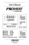
PARTS CATALOG
100,000–TO-DATE
200,000–TO-DATE
Selection Guide
Heat output 45,000 BTU/hr (13.0kw)
Standard Heater Kit For Engine Heat
This selection guide is designed to
help you choose the appropriate
PROHEAT kit for your application.
PH0403
PH0404
12 Volt Standard Heater Kit
24 Volt Standard Heater Kit
Kits Contain:
Basic Heater . . . . . . . . . . . . . . . . . . . .PH0405 or PH0406
Aluminum enclosure box, checker . . . . .PK0200
Installation kit . . . . . . . . . . . . . . . . . . .PK0300 or PK0301
Truck Heater Kit for Engine And Sleeper Heat
PH0401
12 Volt Truck Heater Kit
Kit Contains:
Basic Heater . . . . . . . . . . . . . . . . . . . .PH0405
Aluminum enclosure box, checker . . . . .PK0200
Sleeper control kit (c/w thermostat) . . .PK0050
Installation Kit . . . . . . . . . . . . . . . . . . .PK0300
Basic Heater Without Aluminum Enclosure Box
PH0405
PH0406
12 Volt Basic Heater Kit (requires PK0300)
24 Volt Basic Heater Kit (requires PK0301)
Basic Kit Contains:
Electronic Controller
Coolant Pump
Mounting Base
12 Volt
24 Volt
903100K
940326K
953346K
905300K
942820K
953346K
12 Volt
24 Volt
903223K
814027K
920125K
845028K
903223K
814027K
842725K
845028K
Installation Kit
PK0300
PK0301
Installation Kit (for PH0405) 12V
Installation Kit (for PH0406) 24V
Installation Kit Contain:
Power wire harness
Fuel pick-up and hose
Toggle switch
Exhaust
Nuts, bolts, washers for mounting
Options
PK0001
PK0050
PK0051
PK0053-2
PK0055
PK0151
PK0152
PK0200
PK0202
PK0300
PK0301
Timer, 7 day digital
Sleeper control kit with thermostat
Hour meter kit
Data Link kit
Impact switch kit (for Bus installations)
Across-frame mounting kit
Side-frame mounting kit
Aluminum enclosure box, checker
Aluminum enclosure box, plain
Basic installation kit, 12 Volt
Basic installation kit, 24 volt
XL Series Conversion Kits
956812K
968532K
200449K
969174K
XL900 to X45 – 12 Volt
XL900 to X45 – 24 Volt
XL1500 to X45 – 12 Volt
XL1500 to X45 – 24 Volt
Conversion Kits Include:
956812K
Combustion Tube
844222K
Fan/Blower
948533K
Compressor Fuel Pump 958533K
Necessary Harness
930523K/944124K
968532K
200449K 969174K
844222K
948532K
958532K
935523K/944124K
844222K
980212K
959175K
944124K
844222K
980224K
959174K
944124K
TABLE OF CONTENTS
PART DESCRIPTION
X45
BLOWER
Blower, 12V . . . . . . . . . . . . . . . . . . . . . . . . . . . . . . . . . . .1
Blower, 24V . . . . . . . . . . . . . . . . . . . . . . . . . . . . . . . . . . .1
COMPRESSOR
Air Filter . . . . . . . . . . . . . . . . . . . . . . . . . . . . . . . . . . . . . .4
Compressor, 12V . . . . . . . . . . . . . . . . . . . . . . . . . . . . . . .4
Compressor, 24V . . . . . . . . . . . . . . . . . . . . . . . . . . . . . . .4
Mounting Clamps . . . . . . . . . . . . . . . . . . . . . . . . . . . . . .4
Compressor Rebuild Kit . . . . . . . . . . . . . . . . . . . . . . . . . .6
Compressor Diaphragm Kit . . . . . . . . . . . . . . . . . . . . . . .6
COOLANT PUMPS
Coolant Pump, 12V . . . . . . . . . . . . . . . . . . . . . . . . . . . . .4
Coolant Pump, 24V . . . . . . . . . . . . . . . . . . . . . . . . . . . . .4
Coolant Pump Rebuild Kit . . . . . . . . . . . . . . . . . . . . . . . .5
ELECTRICAL SYSTEM
PCM . . . . . . . . . . . . . . . . . . . . . . . . . . . . . . . . . . . . . . .3,7
Fuse, 15 amp . . . . . . . . . . . . . . . . . . . . . . . . . . . . . . . . . .3
Fuse Holder . . . . . . . . . . . . . . . . . . . . . . . . . . . . . . . . . . .3
Power wire Harness . . . . . . . . . . . . . . . . . . . . . . . . . . . . . .
Main Wire Harness . . . . . . . . . . . . . . . . . . . . . . . . . . . . .3
Sleeper Wire Harness . . . . . . . . . . . . . . . . . . . . . . . . . . .3
Switch Wire Harness . . . . . . . . . . . . . . . . . . . . . . . . . . . .3
EXHAUST SYSTEM
Exhaust Pipe, 10" Long . . . . . . . . . . . . . . . . . . . . . . . . . .2
Exhaust Pipe 90° Elbow . . . . . . . . . . . . . . . . . . . . . . . . . .2
Exhaust Pipe Clamp . . . . . . . . . . . . . . . . . . . . . . . . . . . . .2
FUEL SYSTEM
Nozzle . . . . . . . . . . . . . . . . . . . . . . . . . . . . . . . . . . . . . . .1
Fuel Regulator . . . . . . . . . . . . . . . . . . . . . . . . . . . . . . . . .1
Fuel Pickup . . . . . . . . . . . . . . . . . . . . . . . . . . . . . . . . . . .8
Fuel Pump . . . . . . . . . . . . . . . . . . . . . . . . . . . . . . . . . . . .4
HEAT EXCHANGER
Sight Glass Assy Kit . . . . . . . . . . . . . . . . . . . . . . . . . . . .1
Combustion Tube . . . . . . . . . . . . . . . . . . . . . . . . . . . . . . .2
Heat Exchanger . . . . . . . . . . . . . . . . . . . . . . . . . . . . . . . .2
Rubber Shock Mounts . . . . . . . . . . . . . . . . . . . . . . . .2, 11
TABLE OF CONTENTS
continued
PART DESCRIPTION
X45
IGNITION SYSTEM
Ignition Electrode . . . . . . . . . . . . . . . . . . . . . . . . . . . . . .1
Ignition Lead with Boot . . . . . . . . . . . . . . . . . . . . . . . . . .1
Ignition Coil . . . . . . . . . . . . . . . . . . . . . . . . . . . . . . . . . . .2
SENSORS
Flame Sensor . . . . . . . . . . . . . . . . . . . . . . . . . . . . . . . . . .1
Overheat Sensor . . . . . . . . . . . . . . . . . . . . . . . . . . . . . . .3
Temperature Sensor . . . . . . . . . . . . . . . . . . . . . . . . . . . .3
TEST EQUIPMENT & SPECIAL TOOLS
Test Lead, Main Harness . . . . . . . . . . . . . . . . . . . . . . . .15
Remote ON/OFF Switch . . . . . . . . . . . . . . . . . . . . . . . . .15
Datalink Kit . . . . . . . . . . . . . . . . . . . . . . . . . . . . . . . . . .16
Flow Indicator . . . . . . . . . . . . . . . . . . . . . . . . . . . . . . . .17
Test Gauge, Air Compressor . . . . . . . . . . . . . . . . . . . . .18
ACCESSORIES
Fuel Pickup . . . . . . . . . . . . . . . . . . . . . . . . . . . . . . . . . . .8
Bunk Thermostat . . . . . . . . . . . . . . . . . . . . . . . . . . . . . . .9
Isolator . . . . . . . . . . . . . . . . . . . . . . . . . . . . . . . . . . . . . .9
ON/OFF Switch . . . . . . . . . . . . . . . . . . . . . . . . . . . . . . . .9
Relay . . . . . . . . . . . . . . . . . . . . . . . . . . . . . . . . . . . . . . . .9
Enclosure . . . . . . . . . . . . . . . . . . . . . . . . . . . . . . . . . . . .10
Rubber Mount Kit . . . . . . . . . . . . . . . . . . . . . . . . . . . . .11
Mount Upgrade Kit . . . . . . . . . . . . . . . . . . . . . . . . . . . .11
Auxiliary Base Kit . . . . . . . . . . . . . . . . . . . . . . . . . . . . . .11
Side Frame Mounting Kit . . . . . . . . . . . . . . . . . . . . . . . .12
Across Frame Mounting Kit . . . . . . . . . . . . . . . . . . . . . .13
Timer, 7 Day Digital . . . . . . . . . . . . . . . . . . . . . . . . . . . .14
Ground Wire In-line Fuse . . . . . . . . . . . . . . . . . . . . . . . .14
Air Inlet Hose . . . . . . . . . . . . . . . . . . . . . . . . . . . . . . . . .14
Impact Switch . . . . . . . . . . . . . . . . . . . . . . . . . . . . . . . .14
DOCUMENTATION
Proheat Installation Manual . . . . . . . . . . . . . . . . . . . . . .19
Proheat Warranty Card . . . . . . . . . . . . . . . . . . . . . . . . .19
Proheat Parts Catalog . . . . . . . . . . . . . . . . . . . . . . . . . .19
NUMERIC PARTS INDEX . . . . . . . . . . . . . . . . . . . . .20,21
X45
7
6
2
5
3
4
8
1
11 12
9
1
14
18
17
16
4
13
19
15
14
Figure 1
16
ITEM PART# QTY DESCRIPTION
1
2
3
4
5
6
7
8
9
10
11
12
13
842123K
2
Elbow, 3/16" Hose by 1/8" NPT,
Air & Fuel
954329K 1
Sensor, Flame
934429K 4
Screw, 10-24 NC by 5/8" Hex HD
903628K 4
Screw, Hex Flange, 1/4" NC by 5/8"
953523K 1
Gasket, Seat, Igniter
933525K 1
Igniter, X45 c/w Gasket
930523K 1
Lead, Ignition
844721K 1
Sight Glass Assy Kit
980212K 1
Blower, 12V c/w Fan Blade
980224K 1
Blower, 24V c/w Fan Blade
964424K 1
Gasket, Blower
938326K 1
Nozzle, Fuel, 30609-32 c/w O-Ring
Note: Always check part # on nozzle to ensure
correct replacement part.
221442K 1
O-Ring, Nozzle
932100K 1
Fan End Casting (sub)
c/w Screen & Sight Glass
PROHEAT PARTS CATALOG
10
ITEM PART# QTY DESCRIPTION
14
15
16
17
18
19
880072K 10
Clamp, Spring, 1/4"
934325K 2
Clamp, Screw, 3/16"
Note: 3/16" hose is an obsolete size. Please check
your heater to ensure you are ordering the correct part.
951125K 1
Regulator, Fuel
842020K 1
Hose, Air & Fuel, 1/4" ID, per 5ft.
964321K 1
Screen, Blower Inlet Kit
840429K 1
Clamp, Spring, Green, Air
900316K 1
Fan Blade c/w Glue
PK0069
933525K
938326K
951125K
954329K
930523K
825730K
880035K
X45 MAJOR SERVICE KIT
(not shown)
Kit Includes:
Igniter, X45 c/w Gasket
Nozzle, Fuel, 30609-32 c/w O-Ring
Regulator, Fuel
Sensor, Flame
Lead, Ignition (see page 2)
Filter, Compressor (see page 4)
Filter, Fuel (see page 3)
1
X45
7
6
8
5
4
3
1
2
9
9
14
10
15
12
11
13
(OPTIONAL)
17
OR
16
Figure 2
ITEM PART# QTY DESCRIPTION
2
1
999670K
4
2
3
4
5
6
7
8
9
10
11
12
13
14
15
16
17
020625K
844222K
938928K
936725K
904921K
225527K
934522K
4
1
1
1
2
903628K
334423K
850113K
913526K
909521K
930523K
845028K
980521K
4
1
1
1
1
1
1
1
ITEM PART# QTY DESCRIPTION
Screw, 10-24 NC by 1/2",
Socket HD
Lockwasher, #10, Stainless Steel
Combustion Tube, X45, 12/24V
Nut, Nylon, 1/4" NC JAM
Clamp, Cushioned 3/8" ID
Elbow, 3/4" Hose by 1/2" NPT
O-Ring, Heat Exchanger
Heat Exchanger c/w Elbows
Mounting Hardware (see page 11)
Screw, Hex Flange, 1/4" NC by 5/8"
Clamp, Gear, #32
Bracket, "J" c/w Clamp
Coil, Ignition
Clamp, Exhaust Pipe
Lead, Ignition
Exhaust Pipe, 10" long
Exhaust Pipe, 90° Elbow, 24"
PROHEAT PARTS CATALOG
X45
1
2
3
4
14 15
16
5
13
12
6
7
11
8
10
5
9
Figure 3
ITEM PART# QTY DESCRIPTION
1
2
3
4
5
6
7
8
9
934429K
934626K
901021K
917724K
903628K
931327K
903026K
903120K
903223K
903224K
2
2
1
1
4
1
1
1
1
10
11
12
842528K
905229K
934500K
934520K
3
3
1
1
13
14
15
921823K
901124K
905821K
1
1
1
Screw, 10-24 NC by 5/8" Hex HD
Clip, Wire Harness, 2/Pkg.
Sensor, Overheat c/w O Ring
O-Ring, Overheat
Screw, Hex Flange, 1/4" NC by 5/8"
Cover, Connector
Harness, Sleeper Fan, 30', 2 Pin
Harness, Switch, 25', 4 Pin
Harness, Power, 16', 3 Pin
Harness, Power, 32', 3 Pin
(not shown)
Spacer, Controller
Grommet, Controller Mount
Harness, Main Internal, 12V
Harness, Main, 24V
c/w Ground Fuse
Fuse, 15A, 3/Pkg.
Sensor, Temperature c/w O Ring
O-Ring, Temperature Sensor
PROHEAT PARTS CATALOG
ITEM PART# QTY DESCRIPTION
16
900001K
1
FUSE HOLDER REPLACEMENT KIT
3
X45
7
12
13
1
23
14
11
10
19
20
9
2
15
8
17
18
16
3
7
21
4
6
7
5
22
Figure 4
ITEM PART# QTY DESCRIPTION
1
4
2
3
4
5
930812K
930824K
940732K
980012K
020625K
922680K
1
1
2
1
2
2
6
7
880015K
842123K
1
3
8
9
10
11
12
13
14
15
014925K
880035K
331539K
825730K
254261K
922224K
212476K
067528K
1
1
2
1
1
1
1
4
Compressor, 12V
Compressor, 24V
Coupling
Fuel Pump, Gear c/w Coupling
Lockwasher, #10 Stainless Steel
Screw, SHCS#10-24 x 2 1/2",
Stainless Steel
Fitting, Filter Cap
Elbow, 3/16" Hose by 1/8" NPT,
Air & Fuel
O ring, Fuel Filter
Filter, Fuel
Clamp, Gear #36
Filter, Compressor
Washer, Sealing, 685-002
Screw,1/4"-20 NC
Bracket, Compressor / Fuel Pump
Lockwasher, 1/4"
ITEM PART# QTY DESCRIPTION
16
17
18
19
20
21
22
950121K
961229K
962823K
850113K
903628K
334423K
940326K
942820K
4
1
2
1
2
1
1
1
944026K
23
981324K
PK0094
825730K
880035K
SB0002
SB0052
Bolt, #10-24 x 1/2"
Hose, Coolant, 3/4" ID, per ft.
Clamp, #10 Silicon
Bracket, "J" c/w Clamp
Screw, Hex Flange, 1/4" NC by 5/8"
Clamp, Gear, #32
Coolant Pump, 12 Volt
Coolant Pump, 24 Volt
Harness, Adapter for Alternate
Coolant Pump (not shown)
1
RELIEF VALVE KIT
X45 FALL TUNE-UP KIT
(not shown)
Kit Includes:
Filter, Compressor
Filter, Fuel
Document, Fall Tune-Up
Instructions, Cleaning, X45
PROHEAT PARTS CATALOG
X45
1
2
2
7
3
4
5
6
Figure 5
ITEM PART# QTY DESCRIPTION
865893K
1
2
3
4
5
6
7
8
9
10
1
2
1
1
1
1
4
2
2
2
ITEM PART# QTY DESCRIPTION
COOLANT PUMP REBUILD KIT
Kit Includes:
Cup, Separator
Washer, Thrust
Magnet, Impeller
Shaft, Impeller
O-ring
Pump Body
Screw, Pan Head, #8-32 x 1"
Tie Straps (not shown)
Lube, O-ring (not shown)
Clamps, Hose (not shown)
PROHEAT X45 PARTS CATALOG
5
X45
3
4
1
2
5
6
7
8
9
10
Figure 6
ITEM PART# QTY DESCRIPTION
954685K
1
2
3
4
5
6
7
8
9
10
11
6
1
1
4
1
1
1
1
1
1
1
1
COMPRESSOR REBUILD KIT
Kit Contains:
Disk, Compressor
Diaphragm, Compressor
Lockwasher, #10, Stainless Steel
Washer, Sealing, 685-002
Loctite, 242 (0.5 ml Tube)
Loctite, 271 (0.5 ml Tube)
Filter/Cover, Molded, X45
Intake Disc, Compressor
Fasteners
CNTRWT X45 M/C LRG BRG
Instructions, Compressor
Rebuild Kit (not shown)
ITEM PART# QTY DESCRIPTION
980666K
2
5
6
16
1
1
1
1
COMPRESSOR DIAPHRAGM KIT
Kit Contains:
Diaphragm, Compressor
Loctite, 242 (0.5 ml Tube)
Loctite, 271 (0.5 ml Tube)
Instructions, Compressor
Diaphragm Kit (not shown)
PROHEAT X45 PARTS CATALOG
PROHEAT CONTROL MODULES
1
Figure 7
APPLICATION
Trucks with or without Sleeper Kit
Transit or Coach
School Bus
Heavy Equipment
X45
12V
X45
24V
903100K
904200K
904300K
903100K
N/A
905300K
905300K
905300K
ITEM PART# QTY DESCRIPTION
903100K 1
PCM, Standard, 12 Volt
Note: Used in all X45-12 volt systems (except
Transit). Includes sleeper fan output connector.
ITEM PART# QTY DESCRIPTION
904300K 1
PCM, AUX Input, 12 Volt
Note: School bus applications. Included auxiliaryinput connector for optional supplemental heat.
904200K 1
PCM, Auxiliary Input, 12 Volt
Note: Transit/Coach applications. Includes auxiliaryinput connector for optional supplemental heat.
905300K 1
PCM, Auxiliary Input, 24 Volt
Note: Used in all 24 volt applications. Includes
auxiliary-input connector for optional
supplemental heat.
PROHEAT X45 PARTS CATALOG
7
ACCESSORIES
FUEL PICK-UP
4
1
5
6
3
7
8
2
9
1
Figure 8
ITEM PART# QTY DESCRIPTION
1
2
9880072K 10
Clamp, Spring, 1/4"
934325K 2
Clamp, Screw, 3/16"
Note: 3/16" hose is an obsolete size. Please check
your heater to ensure you are ordering the
correct part.
842020K 1
Hose, Air & Fuel, 1/4" ID, per 5ft.
ITEM PART# QTY DESCRIPTION
3
4
5
6
7
8
9
8
841027K
1
980624K
1
979420K
1
840626K
841224K
841328K
841722K
841121K
1
1
1
1
1
Assembly, Fuel Pick-up, 24"
(Standard)
Assembly, Fuel Pick-up, 12"
(Optional)
Assembly, Fuel Pick-up, 36"
(Optional)
Assemblies Include:
Nut, 5/8" NF, 2/Pkg.
Washer, Top, 1/Pkg.
Gasket, Fuel Pick-Up, 5/Pkg.
Washer, 5/8" ID by 1" OD, 2/Pkg.
Washer, Bottom, 1/Pkg.
Fuel Pick-up
PROHEAT X45 PARTS CATALOG
ACCESSORIES
1
ON/OFF SWITCH
2
ISOLATOR
1
3
THERMOSTAT
1
RELAY
1
2
Figure 9
ITEM PART# QTY DESCRIPTION
ITEM PART# QTY DESCRIPTION
3822248K 1
THERMOSTAT
Thermostat
PK0050
1
1
2
844326K
769125K
1
4
ISOLATOR
Isolator, Sleeper Fan c/w Decal
Connector, Female Spade, 1/4"
778853K
844326K
903026K
1
1
4
1
ON/OFF SWITCH
Switch, On/Off, 12V
Switch, On/Off, 24V
Connector, Female Spade, 1/4"
Decal, Toggle Switch
1
1
RELAY
Relay, 12V 20A
Relay, 24V 20A
1
2
3
1
920125K
842725K
769125K
919626K
754929K
755029K
PROHEAT X45 PARTS CATALOG
SLEEPER CONTROL KIT
c/w Thermostat (not shown)
Kit Includes:
Thermostat
Isolator, Sleeper Fan c/w Decal
Harness, Sleeper Fan, 30', 2 Pin
9
ACCESSORIES
ENCLOSURES
1
9
3
9
4
8
5
BASE PLATE
WELDED IN
7
6
2
Figure 10
ITEM PART# QTY DESCRIPTION
1
2
3
4
5
6
7
8
9
916524K
1
Enclosure Lid, Diamond Plate
c/w Logo
954422K 1
Enclosure Lid, Plain c/w Logo
844420K 1
Enclosure, Base
903929K 4
Grommet, Enclosure, 1-1/2" ID
929628K 2
Nut, Panel, Enclosure Base
845422K 2
Screw, Hex Flange, 5/16" NC by 1"
923829K 4
Screw, 5/16" NC by 1-1/4"
010924K 8
Washer, 5/16"
113820K 4
Nut, Self Locking, 5/16" NC
1
926921K 2 ⁄2 ft. Weather Seal, Enclosure
ITEM PART# QTY DESCRIPTION
PK0200
DIAMOND PLATE ENCLOSURE KIT
Kit Includes Items 1 to 9
PK0202
PLAIN ENCLOSURE KIT
Kit Includes Items 1 to 9
* These enclosures use the 2 piece mounts only. Refer to page 10, figure 9, part #953346K
10
PROHEAT X45 PARTS CATALOG
ACCESSORIES
MOUNTING PLATE FOR 2 PIECE MOUNTS
2
1
5"
6 1/2"
5"
3
1 3/8"
5 1/2"
7"
7 1/2"
8 1/2"
2
4
5
Figure 11
ITEM PART# QTY DESCRIPTION
953346K
2
3
4
8
4
4
5
4
931100K
2
3
4
4
4
4
5
4
4
RUBBER MOUNT KIT
Kit Includes:
Washer, Fender, Stainless Steel
Isolator, 2 pc. (includes 2 parts)
Lockwasher, Fender, 5/16",
Stainless Steel
Bolt, 5/16" Zinc Pltd.
ITEM PART# QTY DESCRIPTION
PK0065
1
1
2
3
4
8
4
4
5
4
AUXILIARY BASE KIT
Kit Includes:
Base Mounting Plate
(2 pc. Isolator)
Washer, Fender, Stainless Steel
Isolator, 2 pc. (includes 2 parts)
Lockwasher, Fender, 5/16",
Stainless Steel
Bolt, Zinc Pltd., 5/16"
MOUNT UPGRADE KIT
(for old style enclosures).
Kit Includes:
Washer, Fender, Stainless Steel
Isolator, 2 pc. (includes 2 parts)
Lockwasher, Fender, 5/16",
Stainless Steel
Bolt, 5/16" Zinc Pltd.
Spacer, Isolator (not shown)
PROHEAT X45 PARTS CATALOG
11
ACCESSORIES
MOUNTING KITS
SIDE FRAME
4
3
LOCATION DETAIL
3
2
1
Figure 12
ITEM PART# QTY DESCRIPTION
PK0152
1
2
3
4
12
2
4
8
4
ITEM PART# QTY DESCRIPTION
SIDE FRAME MOUNTING KIT
Kit Includes:
Bracket
Bolt, 3/8" NC by 1-1/2" Hex HD
Washer, 3/8" Flat
Nut, Self Locking, 3/8" NC
PROHEAT X45 PARTS CATALOG
ACCESSORIES
MOUNTING KITS
ACROSS FRAME
LOCATION DETAIL
3
5
1
4
2
Figure 13
ITEM PART# QTY DESCRIPTION
PK0151
1
1
1
3885564K 4
2
3
4
5
1
1
1
1
ITEM PART# QTY DESCRIPTION
ACROSS FRAME MOUNTING KIT
Kit Includes:
Tray
CLAMP ASSEMBLIES
Clamp Assemblies Include:
Block Clamp
Bolt, 3/8" NC by 1" Hex HD
Washer, 3/8" (per assembly)
Lockwasher, 3/8"
PROHEAT X45 PARTS CATALOG
13
ACCESSORIES
IN-LINE FUSE GROUND WIRE
(INTERNAL HARNESS)
AIR INLET HOSE
2
1
TIMER
4
5
IMPACT SWITCH
3
Figure 14
ITEM PART# QTY DESCRIPTION
1
2
3
14
PK0310
PK0320
PK0055
1
IN-LINE FUSE GROUND WIRE
Ground Wire, In-line Fuse
1
AIR INLET HOSE
Hose, Air Inlet, 2 ft.
1
IMPACT SWITCH
Impact Switch
ITEM PART# QTY DESCRIPTION
4
PK0001
1
5
961125K
1
2
2
1
2
2
4
1
TIMER
Timer, 7-day Digital
c/w Installation Kit
Installation Kit, Timer
Kit Contains:
Washer, #8
Nut, Hex #8-32
Bracket, Mounting
Screw, Self Tapping, #8 x 1/2"
Stud, Skt. Hd., #8-32 x 1"
Velcro, Dualock
Wire, Backlight c/w Connector
PROHEAT X45 PARTS CATALOG
TEST EQUIPMENT & SPECIAL TOOLS
TEST LEADS
Figure 15
ITEM PART# QTY DESCRIPTION
967921K
ITEM PART# QTY DESCRIPTION
TEST LEAD, MAIN HARNESS
This lead allows the user to:
• apply power to components
from a remote source
• check the internal resistance
of components
• check component voltages
using a multimeter
• check components
amperage using a multimeter
ON/OFF
SWITCH
CABLE LENGTH 24"
Figure 16
ITEM PART# QTY DESCRIPTION
952925K
ITEM PART# QTY DESCRIPTION
REMOTE ON/OFF SWITCH LEAD
This switch lead allows the user
to switch the Proheat ON & OFF
at the PCM.
PROHEAT X45 PARTS CATALOG
15
TEST EQUIPMENT & SPECIAL TOOLS
DATA LINK KIT
PROHEAT
CONTROL
MODULE
(PCM)
2
3
SERIAL CABLE
POWER CABLE
1
5 9 PIN/25 PIN
CONNECTOR
ADAPTER
4
TCIOTNIOS
IINNSSTTRRUUC
Figure 17
ITEM PART# QTY DESCRIPTION
PK0053-2
PROHEAT DATA LINK KIT
Allows the user to download
information stored in the PCM into
a computer for viewing.
The information can be used to:
a) determine the number of hours
the heater has run
b) aid in troubleshooting
ITEM PART# QTY DESCRIPTION
1
2
1
1
3
4
5
1
1
1
1
16
Package includes:
Software, Data Link – CD
Serial Cable – Connects Computer
to Controller (25' long)
Power Cable (15' long)
Instructions
9 pin/25 pin Connector Adapter
Not included:
Computer: IBM Compatible
with Serial Port
PROHEAT X45 PARTS CATALOG
TEST EQUIPMENT & SPECIAL TOOLS
FLOW
FLOW INDICATOR
CONNECTION DETAIL
SLEEPER FAN
FLOW
INDICATOR
Figure 18
ITEM PART# QTY DESCRIPTION
TK9002
FLOW INDICATOR
Allows the user to determine:
• direction of flow
• speed of flow
• air (if any in the coolant system.)
PROHEAT X45 PARTS CATALOG
17
TEST EQUIPMENT & SPECIAL TOOLS
LINE NOZZLE
AIR INLET (MAX 6")
GAUGE
LINE FROM COMPRESSOR
Figure 19
ITEM PART# QTY DESCRIPTION
PK0060
TEST GAUGE, AIR COMPRESSOR
This tool is used to check for proper
air/fuel delivery through the nozzle.
Refer to page 5 -14 of Service
Manual for further information.
18
PROHEAT X45 PARTS CATALOG
DOCUMENTATION
1
2
INSTALLATION
MANUAL
3
SERVICE
MANUAL
PARTS CATALOG
100,000–TO-DATE
200,000–TO-DATE
4
Figure 20
ITEM PART# QTY DESCRIPTION
1
2
3
4
5
925832
925834
SL9070
SL9035
SL9035X
1
1
1
1
1
ITEM PART# QTY DESCRIPTION
Installation Manual
Service Manual
Parts Catalog
Timer Instruction Card
Trouble Shooting Codes
(not shown)
PROHEAT X45 PARTS CATALOG
19
NUMERIC PARTS INDEX
PART#
DESCRIPTION
010924K
014925K
020625K
067528K
113820K
212476K
221442K
225527K
254261K
331539K
334423K
3822248K
3885564K
754929K
755029K
769125K
778853K
825730K
840429K
840626K
842020K
841027K
841121K
841224K
841328K
841722K
842123K
Washer, 5/16" ............................................10
O ring, Fuel Filter ...........................................4
Lockwasher, #10, Stainless Steel...............2, 4
Lockwasher, 1/4"..........................................4
Nut, Self Locking, 5/16" NC.........................10
Bracket, Compressor / Fuel Pump ..................4
O-Ring, Nozzle ...............................................1
O-Ring, Heat Exchanger ..................................2
Washer, Sealing, 685-002..............................4
Clamp, Gear #36 ...........................................4
Clamp, Gear, #32 ......................................2, 4
Thermostat....................................................9
Clamp Assemblies .......................................13
Relay, 12V 20A .............................................9
Relay, 24V 20A .............................................9
Connector, Female Spade, 1/4" .....................9
Thermostat....................................................9
Filter, Compressor .....................................1, 4
Clamp, Spring, Green, Air ...............................1
Nut, 5/8" NF, 2/Pkg. .....................................8
Hose, Air & Fuel, 1/4" ID, per 5ft. ..............1, 8
Assembly, Fuel Pick-up, 24" ...........................8
Washer, Bottom, 1/Pkg..................................8
Washer, Top, 1/Pkg. ......................................8
Gasket, Fuel Pick-Up, 5/Pkg. ..........................8
Washer, 5/8" ID by 1" OD, 2/Pkg...................8
Elbow, 3/16" Hose by 1/8" NPT,
Air & Fuel ..................................................1, 4
Spacer, Controller ..........................................3
Switch, On/Off, 24V.......................................9
Combustion Tube, X45, 12/24V .....................2
Isolator, Sleeper Fan c/w Decal ......................9
Isolator .........................................................9
Enclosure, Base ..........................................10
Sight Glass Assy Kit.......................................1
Exhaust Pipe, 10" long...................................2
Screw, Hex Flange, 5/16" NC by 1" ..............10
Bracket, "J" c/w Clamp ..............................2, 4
Coolant Pump Rebuild Kit ...............................5
Fitting, Filter Cap ...........................................4
Filter, Fuel .................................................1, 4
Clamp, Spring, 1/4" ......................................1
Fuse Holder Replacement Kit..........................3
Fan Blade c/w Glue .......................................1
Sensor, Overheat c/w O Ring .........................3
Sensor, Temperature c/w O Ring ....................3
Harness, Sleeper Fan, 30', 2 Pin ................3, 9
PCM, Standard, 12 Volt..................................7
Harness, Switch, 25', 4 Pin ............................3
Harness, Power, 16', 3 Pin.............................3
Harness, Power, 32', 3 Pin.............................3
842528K
842725K
844222K
844326K
844326K
844420K
844721K
845028K
845422K
850113K
865893K
880015K
880035K
880072K
900001K
900316K
901021K
901124K
903026K
903100K
903120K
903223K
903224K
20
PAGE#
PART#
DESCRIPTION
903628K
903929K
904200K
904300K
904921K
905300K
905229K
905821K
909521K
913526K
916524K
917724K
919626K
920125K
921823K
922224K
922680K
Screw, Hex Flange, 1/4" NC by 5/8"............1-4
Grommet, Enclosure, 1-1/2" ID ...................10
PCM, Auxiliary Input, 12 Volt...........................7
PCM, AUX Input, 12 Volt.................................7
Elbow, 3/4" Hose by 1/2" NPT.......................2
PCM, Auxiliary Input, 24 Volt ..........................7
Grommet, Controller Mount ............................3
O-Ring, Temperature Sensor ...........................3
Clamp, Exhaust Pipe ......................................2
Coil, Ignition ..................................................2
Enclosure Lid, Diamond Plate c/w Logo ........10
O-Ring, Overheat............................................3
Decal, Toggle Switch ......................................9
Switch, On/Off, 12V.......................................9
Fuse, 15A, 3/Pkg. .........................................3
Screw,1/4"-20 NC .........................................4
Screw, SHCS#10-24 x 2 1/2",
Stainless Steel ..............................................4
Screw, 5/16" NC by 1-1/4"..........................10
Installation Manual ......................................19
Service Manual............................................19
Weather Seal, Enclosure ..............................10
Nut, Panel, Enclosure Base ..........................10
Lead, Ignition ............................................1, 2
Compressor, 12V...........................................4
Compressor, 24V...........................................4
Mount upgrade Kit ......................................11
Cover, Connector ...........................................3
Fan End Casting (sub) c/w Screen
& Sight Glass ................................................1
Igniter, X45 c/w Gasket .................................1
Clamp, Screw, 3/16" ................................1, 8
Screw, 10-24 NC by 5/8" Hex HD ...............1, 3
Harness, Main Internal, 12V ...........................3
Harness, Main, 24V c/w Ground Fuse .............3
Heat Exchanger c/w Elbows............................2
Clip, Wire Harness, 2/Pkg. .............................3
Clamp, Cushioned 3/8" ID .............................2
Nozzle, Fuel, 30609-32 c/w O-Ring .................1
Nut, Nylon, 1/4" NC JAM................................2
Coolant Pump, 12 Volt ...................................4
Coupling .......................................................4
Coolant Pump, 24 Volt ...................................4
Harness, Adapter for Alternate Coolant Pump ..4
Bolt, #10-24 x 1/2" .......................................4
Regulator, Fuel ..............................................1
Remote On/Off Switch Lead .........................15
Rubber Mount Kit ........................................11
Gasket, Seat, Igniter ......................................1
Sensor, Flame ...............................................1
Enclosure Lid, Plain c/w Logo .......................10
923829K
925832
925834
926921K
929628K
930523K
930812K
930824K
931100K
931327K
932100K
933525K
934325K
934429K
934500K
934520K
934522K
934626K
936725K
938326K
938928K
940326K
940732K
942820K
944026K
950121K
951125K
952925K
953346K
953523K
954329K
954422K
PAGE#
PROHEAT X45 PARTS CATALOG
NUMERIC PARTS INDEX
PART#
DESCRIPTION
954685K
961125K
961229K
962823K
964321K
964424K
967921K
979420K
980012K
980212K
980224K
980521K
980624K
980666K
981324K
9880072K
999670K
PK0001
PK0050
PK0069
PK0065
PK0094
PK0151
PK0152
PK0053-2
PK0055
PK0060
PK0200
PK0202
PK0310
PK0320
SB0002
SB0052
SL9035
SL9035X
SL9070
TK9002
Compressor Rebuild Kit..................................6
Installation Kit, Timer ...................................14
Hose, Coolant, 3/4" ID, per ft. ......................4
Clamp, #10 Silicon ........................................4
Screen, Blower Inlet Kit ..................................1
Gasket, Blower ..............................................1
Test Lead, Main Harness .............................15
Assembly, Fuel Pick-up, 36" ...........................8
Fuel Pump, Gear c/w Coupling ........................4
Blower, 12V c/w Fan Blade ............................1
Blower, 24V c/w Fan Blade ............................1
Exhaust Pipe, 90° Elbow, 24" .........................2
Assembly, Fuel Pick-up, 12" ...........................8
Compressor Diaphragm Kit .............................6
Relief Valve Kit ..............................................4
Clamp, Spring, 1/4" ......................................8
Screw, 10-24 NC by 1/2", Socket HD .............2
Timer, 7-day Digital c/w Installation Kit..........14
Sleeper Control Kit c/w Thermostat.................9
X45 Major Service Kit ....................................1
AuxilIary Base Kit ........................................11
X45 Fall Tune-Up Kit ......................................4
Across Frame Mounting Kit ...........................13
Side Frame Mounting Kit ..............................12
Proheat Data Link Kit ...................................16
Impact Switch..............................................14
Test Gauge, Air Compressor .........................18
Diamond Plate Enclosure Kit.........................10
Plain Enclosure Kit.......................................10
Ground Wire, In-line Fuse..............................14
Hose, Air Inlet, 2 ft. .....................................14
Document, Fall Tune-Up..................................4
Instructions, Cleaning, X45.............................4
Timer Instruction Card ..................................19
Trouble Shooting Codes ...............................19
Parts Catalog...............................................19
Flow Indicator ..............................................17
PROHEAT X45 PARTS CATALOG
PAGE#
PART#
DESCRIPTION
PAGE#
21
Teleflex Canada Limited Partnership
3831 No. 6 Road
Richmond, BC
Canada V6V 1P6
Tel: (604) 270-6899
Fax: (604).270-0137
www.proheat.com
Designed and Manufactured
in North America
© 2007 Teleflex Canada
Printed in Canada 11/07
SL9070E-01