1
Mounting Instructions
WITH SET-UP DATA
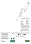
SHOCK ABSORBER HD744
for Harley Davidson Sportster
Before installing this shock absorber,
check the contents of the kit listed
below. If anything is missing, please
contact your nearest Öhlins dealer.
Kit Contents:
Shock absorber
Sleeve
Washer
Öhlins Sticker
Owner’s Manual
Part no.
HD744
00123-13
03118-08
00192-01
07241-02
Pcs.
2
4
8
2
1
During storage and transportation,
especially at high ambient temperature, some of the oil and grease used
for assembling may leak and stain
the packaging. This is in no way detrimental to the product, wipe off the
excessive oil/grease with a cloth.
Set-up Data
Spring preload
Compression damping
Rebound damping
15 mm
2 clicks
18 clicks
Shock absorber length 360 (+10/-0) mm
Stroke
101 mm
Before installing this product, read the Öhlins Owner’s Manual!
© Öhlins Racing AB. All rights reserved. Any reprinting or unauthorized use without the written
permission of Öhlins Racing AB is prohibited.
Printed in Sweden.
Mounting Instructions HD744_0 Issued 2006 12 13
These instructions and other documents
can be downloaded from
www.ohlins.com
may
approvaffect
Installin ed by the stabilit
the vehicle
y of
g a shock
your
absorb manufa vehicle
may
er that cturer .
is not
approvaffect
Installin ed by the stabilit
the vehicle
y of
g a shock
your
absorb manufa vehicle
er that cturer .
may
is not
approvaffect
Installin ed bythe stabilit
the vehicle
y of
g a shock
your
absorb manufa vehicle
may
er that cturer .
approvaffect
is not
Installin ed bythe stabilit
the vehicle
y of
g a shock
your
absorb manufa vehicle
er that cturer .
is not
Öhlins Racing AB, Box 722, S-194 27 Upplands Väsby, Sweden.
Phone +46 8 590 025 00 Fax +46 8 590 025 80
www.ohlins.com
HOW TO INSTALL
WARNING!
It is advisable to have an Öhlins dealer install the
shock absorber.
1
Put the motorcycle on a workstand so that the
rear wheel barely touches the ground.
ADJUSTMENTS
NOTE!
Lower the motorcycle so that the shock
absorber is sligthly compressed, before tightening the screws.
Always ensure that the basic settings made by
Öhlins are intact.
1
Make sure that all screws are tightened to the
correct torque and that nothing fouls or restricts
movement of the shock absorber when the suspension is fully compressed or extended.
WARNING!
2
Make sure the vehicle is securely supported so
that it will not tip.
2
Spring Preload
Turn the knob on the hydraulic preload
adjuster. Turn clockwise to increase the
spring preload. Turn counter clockwise to
release it.
2
Compression Damping
Turn the wheel on top of the reservoir.
The adjustments are made in four (4)
steps.
1
00123-13
Remove the original shock absorbers. Consult
your Vehicle Service Manual.
3
NOTE!
Recommendation! Before installing the Öhlins
shock absorber:
• clean the vehicle thoroughly
• adjust the length of the shock absorber (check
the headlight angle after adjusting the length!)
Rebound Damping
Turn the adjuster wheel on the piston
shaft above the end eye.
WARNING!
03118-08
When delivered, the Öhlins shock absorber is
dialed to the recommended settings for the specific brand and make of the motorcycle. Before
riding, always ensure that the basic settings
made by Öhlins are intact.
3
To set the adjuster:
The turn adjusters have a normal right hand
thread. Turn the damping adjusters clockwise to fully closed (position zero [0]). Then,
turn counter clockwise to open, and count
the clicks until you reach the recommended
number of clicks. See Set-up data.
Install the Öhlins shock absorbers in the same
way as the original units. The shock absorber
should be installed with the cylinder head at
the top and the reservoir towards the rear. Use
the washers and sleeves provided in this kit.
3
4
Do not use force, delicate sealing surfaces can
be damaged. Handtighten only.
4
00123-13
03118-08
Length
Use two wrenches. Hold the upper nut
with one hand and at the same time
loosen the lock nut (lower nut). Turn the
end eye/ bracket to the desired length.
Lock the lock nut.
WARNING!
The adjustable end eye/bracket must not be
threaded out more than that the groove is fully
visible beneath the lock nut. This is maximum
length. After adjusting, make sure that the lock
nut is tightened.