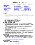
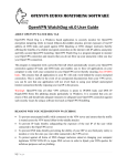
1
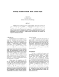
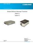
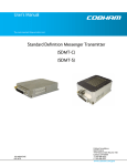
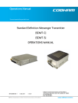
The Ultimate Mod, An Electronic Cruise Control For Your FI Vulcan
12/04/2005 12:55 AM
Electronic Cruise Control
For Nomad & Classic FI 1500 & 1600
Let's begin with the disclaimer shall we?
This is not an attempt to scare anyone off the project but it is NOT a task for the timid. You will be
involved with a considerable amount of electrical wiring, you will be slightly modifying the inner liner
of your left side cover box ( just drilling some holes and making one slot), you will be cutting a
vacuum hose (just a tiny one), you will be removing the gas tank (no getting around it this time) and
you will have to READ THE INSTRUCTIONS very carefully. Click Here to see the AudioVox
instruction manual in .PDF format. Not gone yet? Great!
I wasn't kidding about reading the instructions. This page will go into tremendous (sometimes over
the top) detail and there will be many pictures and drawings to help. After reading everything on the
page I would strongly suggest printing it all, even the full size pictures (get them by clicking on
thumbnails) and put it all in a binder of some sort so you don't end up with paperwork scattered all
over the garage. You may also want to check things off as you go or (shades of college) write in the
margins so a pen clipped or tied to the binder wouldn't be a bad idea. If you install the cruise control
using these instructions I'd appreciate an e-mail from you noting any questions that arose because
something wasn't made clear. I'll make corrections so the question doesn't arise for the next installer.
You can install the Audiovox kit using only the parts that come in the box. Bob Sanders has done this
(as have several other owners). His parts list (all items in the kit) and how he used each of them is
listed separately near the bottom of this page here. You'll also find alternate ways to the same end
provided by Max French here. Notice the photos on this page show a modification made to the left
side cover inner liner on a 1500 Vulcan. If you have a 1600 there will be a link provided showing how
you need to modify your liner. Don't panic, it's only plastic.
A gentleman named Wilfred Caveda made the stainless steel brackets you'll see in the following
instructions but items supplied in the kit are similar and can be used instead. My thanks to Wilfred
for getting this project off the ground.
Nomad and Classic owners who have followed the instructions posted here (along with those that
came with the Audiovox unit) report it is a reasonably easy job when broken down into individual
components.
http://gadgetjq.com/electronic_cruise.htm
Page 1 of 15
The Ultimate Mod, An Electronic Cruise Control For Your FI Vulcan
12/04/2005 12:55 AM
Ok, lets do this. The following instructions are in sections. We start with "what you need" and work
our way through tools, electrical and vacuum (and occasionally back again). Take it section by
section and you'll discover it really isn't that hard a job. Challenging? Yes. Hard? No.
What You'll Need
1- Audiovox CCS-100 Cruise Control Kit This is available (at this writing) through J.C. Whitney on
this page @ $119.95 or at Summit Racing $89.95. Shop around on the Internet for best pricing.
1- #2-970 Vacuum check valve from NAPA or equivalent
1- 2" PVC slip-on coupling, (not a repair coupling, which are shorter in length) the length should be
almost 3" long. You 'might' be able to find this part at a large hardware store like Lowes or Home
Depot but more likely a plumbing supply business that deals with PVC pipe (sprinkler systems) on a
regular basis. See Picture #14
2- 2" PVC slip-on plugs (not caps) close to 1 7/16" in length. As above if you can't find these parts at
a hardware store check a plumbing supply. See Picture #14
2- Brass elbows, 1/8" male pipe thread x 1/8" female pipe thread
2- Brass adapters, 1/8" male pipe thread x 3/16" barbed end (for connecting vacuum hose)
1- Small can PVC pipe glue
1- Small can PVC cleaner
1- Teflon tape
4- 3/16" thick spacers (to hold the side cover inner liner slightly away from the bike. A couple of
thick washers will do or find some plastic spacers as shown in Picture #11
1- Piece of firm foam to fit behind the vacuum canister as shown in picture #4
Assorted sizes of shrink tubing to insulate electrical connections
Basic tools should include
Allen wrenches
1/8" pipe thread tap (so brass fittings can be screwed into the vacuum reservoir)
Needle nose pliers (unless you have really tiny fingers)
Heat gun or cigarette lighter for shrink tubing
Assorted metric sockets
Screwdrivers
If you're modifying your own side cover
Electric drill & bits
If you'll be making your own brackets a full machine shop would be nice but you can probably get
http://gadgetjq.com/electronic_cruise.htm
Page 2 of 15
The Ultimate Mod, An Electronic Cruise Control For Your FI Vulcan
12/04/2005 12:55 AM
away with a Dremel tool. A Dremel tool is also handy for modifying the inner liner of the side cover.
Installation
This has already been said but let me say it again. Please read these instructions and those that come
with the Audiovox unit completely through before beginning. It is extremely important you be
familiar with all procedures before digging in.
The Installation begins with the set-up of the DIP SWITCHES or what Audiovox calls,
"PROGRAMMING THE SERVO ASSEMBLY". Remove the cover on the back of the servo unit
and set the switches to the following positions
SW # 1 = ON
SW # 2 = OFF (You are setting these two switches for 4000 PPM since this is a manual transmission
vehicle and will operate from the TACH signal only.
SW # 3 = OFF (TACH signal only)
SW # 4 = OFF
SW # 5 = OFF (These settings are for "Medium Sensitivity" You may decide later to change settings
for "Low Sensitivity" if the bike seems jerky or is too reactive for your particular riding environment
or to "high" sensitivity if you live in an area with very hilly terrain and you want the CC to react
quickly to elevation changes.. Go with "medium" first.)
SW # 6 = OFF (The Dash Mounted Control Switch supplied in the kit is a Normally Open type.)
SW # 7 = ON (TACH source only)
VERY IMPORTANT: REMOVE THE WIRE JUMPER UNDER THE L.E.D AT THE LEFT OF
THE DIP SWITCHES. This is to enable the feature that lets your cruise control disconnect when the
clutch is applied. This works by sensing a sudden increase in engine RPM caused by disengaging the
clutch. The system works very quickly with RPM only going up by about 50 before the Cruise
Control is cancelled. Note, you can 'resume' the originally set speed by pressing the 'resume' button.
Do Not Put The Cover Back On The Servo Yet . Set the servo aside, we'll move on to the next
project
The Vacuum System
The Vacuum Reservoir can be made with PVC fittings as follows: (BTW, this canister provides 15 cu.
in. of vacuum, more than sufficient vacuum for small engine like this) For the Nomad and Classic you
can NOT use the accessory AudioVox control vacuum canister sold by J.C. Whitney. The
commercially available canister measures 4" tall and 3.5" wide so it's 5/8" too wide to fit between the
inner liner and outer side cover.
http://gadgetjq.com/electronic_cruise.htm
Page 3 of 15
The Ultimate Mod, An Electronic Cruise Control For Your FI Vulcan
12/04/2005 12:55 AM
Begin assembling your canister (shown unassembled in Picture 14 and completely assembled in
Picture #4 below) by drilling the two holes for the brass fittings on the end of one of the plugs (5/16")
(this step needs to be done first, to allow the last PVC plug to go in, and for the glue to dry inside the
reservoir)
Assemble the reservoir by first cleaning all components with PVC cleaner (you must do this to prevent
leaks) then gluing the two plugs inside the coupling, don’t push the plugs all the way in, they should
be left ½" from the bottom, the entire assembly should be around 4-11/16" long, after the PVC
cement is completely dry the reservoir can be painted with Krylon semi-flat black paint to match
other components, then the holes should be tapped in the end of the top PVC plug with a 1/8" pipe
thread tap, the brass elbows can now be screwed into the cap using Teflon tape in the thread. Next
install the barb fittings on the elbows using Teflon tape. The assembly will be mounted in the
compartment as shown in picture # 4 and #5 below.
Set the vacuum canister aside and modify your left side compartment
Remove the outside cover (the one with the lock) and set aside. You won't modify this part at all.
Remove the box where the tools are located in the bottom (this part is not going to be re-used,
relocate the tools in the place of your choice. If you have a California bike you will have to remove or
relocate the charcoal canister. If you are removing it just disconnect the two hoses and connect the
hoses together using the straight through plastic barbed fitting you'll find in the CC kit (part # 7).
Remove the inside compartment by removing the four bolts that support it to the frame, these bolts
will be reused.
The bracket for the Servo Assembly should be modified as shown in picture # 2 (you can do this by
simply bending the bracket around the servo or the more involved bend shown) and installed in the
compartment as in picture # 4. Where the cable leaves the compartment (note arrow in picture) a cut
should be made to accommodate it. The Servo orientation seems to vary slightly depending where the
factory drilled mounting holes for the bracket. Ideally the vacuum fitting will be oriented upward
slightly. Before installing the Servo you need to connect the supplied wiring harness. There is only
one way to plug it in successfully. Note location of the blank.
If you haven't already done so this is the time to remove the seat (two 10 mm bolts, one on each side at
the rear of the seat. Remove the bolts and lift seat from the front) and gas tank. If you've never
removed your tank before refer to the instructions on this fixit page. Set the tank aside in a safe spot
where you won't trip over it.
Install the vacuum canister and servo in your modified side cover as shown in picture #5 using zip
ties.
You will install your modified compartment on the bike using with four spacers 3/16" thick as shown
http://gadgetjq.com/electronic_cruise.htm
Page 4 of 15
The Ultimate Mod, An Electronic Cruise Control For Your FI Vulcan
12/04/2005 12:55 AM
in picture # 11 to provide room for the screws and ties in the back. The spacers are necessary to
allow for the servo bracket mounting screws and zip ties between the compartment and the battery
box. For now just slip the compartment into place and install a single bolt to prevent movement.
Don't bolt it down completely yet.
Time to make the servo cable run
Look at your frame about the center of where the gas tank would be and you'll note a round cross
tube. Route the servo cable out of the side cover, along the left upper frame tube and then 'through'
the frame (left to right) where that cross tube is. There is a lot of "stuff" in that area so use a
flashlight and route the cable slowly through the area so it isn't touching anything that might move
with the engine (we don't need hoses chafing). Once through the frame route the cable down the
right side of the air box (as you're facing the right side of the bike) and loop it 'under the air box.
We really lucked out here, the cable is precisely the correct length for our application. Whew!
Eventually you might want to cover the cable with 1/4" (chrome?) wire loom but there's no need for
that right now.
Remove the right side air box and set aside.
Remove the backing plate by removing two screws holding the backing plate to the air tunnel, one
chrome (go figure) bolt and several Allen head screws holding the backing plate to the throttle body.
Also unclamp and remove the two small air hoses from the idle air solenoids where they seem to
'enter' the air box. Pull the backing plate away from the bike. You can let it hang from the small
hose and wiring harness at the bottom or use a little bit of utility wire and secure it out of the way.
On the handlebar, remove the two screws holding the right side switch box together. Unhook the
"return" cable from the throttle to allow slack at the other end.
Install bracket # 1,
if you are using Wilfreds brackets (remember to see below if
you are working with parts directly from the kit) at the end of the return accelerator cable at the
throttle body, looking at it from the right side of the bike, part # 1 will be installed in the right side of
the cable end. Use a piece of wire hanger or small screwdriver to loosen the cable end only to the
point where it can be slid to the left slightly. Just enough to make space to install the # 1 bracket, the
side where the bead chain will be connected should be on the left side after the bracket is in place.
http://gadgetjq.com/electronic_cruise.htm
Page 5 of 15
The Ultimate Mod, An Electronic Cruise Control For Your FI Vulcan
12/04/2005 12:55 AM
Now bracket # 2
can be attached to the end of the Servo cable in the threaded
part, see picture # 6 or picture # 7.
In the kit, find a bead coupling Audiovox part # 24 (shown in instructions). Cut nine balls from the
bead chain Audiovox part # 20. You will be using just this piece of chain (9 balls). In the kit, find the
bead adapter Audiovox part # 25 (small hole) to connect the end of the Servo cable to bracket # 1 in
the throttle body. You may find you have to open the coupling where the chain is supposed to slip
through. use a small knife to gain clearance here. Insert the chain (9 balls long) one end to the Servo
cable end with the connector # 24 mentioned. Slip two 1/2" inch long pieces of shrink tubing ( suggest
part #B-SMDT-350 from www.smallparts.com) but you can use the tubing (part #23) over the chain
then connect the other end of the chain to part 25 then to the attachment bolt in bracket # 1. Crimp
the chain connectors with your needle nose pliers then use a heat gun to shrink the tubing over the
chain couplers so there's no way they can come unhooked. See picture # 7 for a completed job.
Now you can install bracket # 4,
this replaces the three tabbed original
bracket and is designed (note it is a little longer and has a bend) to prevent the chain from coming in
contact with any part of the bike including your spark plug wire. Bracket #2 installs under bracket
#4 on the left side. The right side is connected the same as the original. When installed correctly the
chain will collapse slightly every time the accelerator is applied and needs room for its movement.
The brackets are formed to accomplish this. Note the MAXIMUM amount of slack in the chain
should be 3 mm and can be set by tightening or loosening the cable in bracket #2. Also note after
some use the cable will stretch just a little so you may have to go back and adjust the amount of slack
http://gadgetjq.com/electronic_cruise.htm
Page 6 of 15
The Ultimate Mod, An Electronic Cruise Control For Your FI Vulcan
12/04/2005 12:55 AM
again. On re-assembly, attach the spark plug cable to #2 cylinder to the #4 bracket using two zip ties.
One under the cable to prevent it contacting the bracket, the other connecting the cable to the
bracket.
When all brackets are tightened and you've checked for binding or interference, re-assemble the right
side air box and your throttle.
You're finished with the mechanical portion of the project.
Now we move to the installation of the vacuum hose to the engine source and this was a pain in the
patoot. You'll be reaching down into a very crowded space atop the throttle body to cut a vacuum
line and insert the small "T" fitting in the CC kit. Not to worry, it can be done...just don't start it if
you're already pissed off at something else. Calm now? Ok.
Reference this photo for Nomad and Classic 1500 FI's
from the Service
Manual where there is an arrow and notation to CUT HERE. With that photo in hand stand over
your bike and look down on the top of the engine (note arrow in picture points to front of bike) just
behind that tubular cross bar referenced earlier. Get some light in there and you'll notice it matches
exactly with the photo. Find the vacuum hose the arrow points to. Check again. Check again. If
you're sure it's the correct hose cut it in half. Unless you have piano player fingers you'll need to
hold one half of the hose with needle nose pliers while you push and twist and wrestle the "T" fitting
into the hose. A little bit of silicone spray or high vacuum grease (a very thick silicone grease used in
the air conditioning trade) will help ease the struggle somewhat. Don't call it done prematurely,
make sure the "T" fitting can't pull loose from the hose. Got it? Now connect the left side. This is
easier if you completely remove the little hose from the valve it's connected to. Push it off with a
screwdriver (don't let it fall into the black hole). Using your pliers again attach the hose to the "T"
fitting then re-attach to the valve. Another option if there's no way you'll be able to get your fingers
in there. Just slip the hose described above off the connection on the left side, slip your "T" into the
hose then use a couple of inches of the supplied hose in the kit to go from the left side of the "T" back
to the gizmo you removed the stock hose from.
http://gadgetjq.com/electronic_cruise.htm
Page 7 of 15
The Ultimate Mod, An Electronic Cruise Control For Your FI Vulcan
12/04/2005 12:55 AM
The vacuum hose is in a slightly different location on the 1600 Nomad/Classic
The picture is from the Kawasaki 1600 service manual. The vacuum
hose you need is labeled "C" in the picture.
Now connect the long vacuum hose (part #10) supplied with the kit to the remaining arm of the "T"
fitting. Route the hose back to the left side cover via the same route you used for the servo cable.
You'll have too much tubing (a good thing). Find a suitable place inside the left side cover to place
the vacuum check valve and (making sure you've allowed some slack for proper routing of the hose)
cut the hose. Attach the black side of the check valve to this vacuum source hose. Attach some hose
to the other (blue) side of the check valve and that hose to one of the barbed fittings on your vacuum
canister. (If you purchase a check valve different from the one shown in picture #12 check to be sure
air will only flow toward the engine and not back toward the vacuum canister.) The other barbed
fitting on the canister can now be connected with your remaining hose (or portion of it) to the vacuum
connection on the servo assembly.
Vacuum work done!
Electrical Connections:
Ok this is going to be the tedious time consuming part. If possible all connections should be soldered.
While this isn't an absolute requirement soldered joints will take up less room than crimp connectors
and will provide a far more reliable electrical connection.
Note the wiring diagram and the text where you will have some options. Some riders prefer making all
wiring connections under the seat, others don't have any problem with making some connections in
the headlight bucket. The power, ground and switch lighting connections can go either place. My
suggestion would be to connect power (red) ground (black) and switch lighting (gray) in the headlight
bucket, all other wiring under the seat.
Connections will be as follows:
Wires from the switch:
Green = connect to Green wire in the Servo Assembly
Black = connect to the battery. negative terminal.
Grey = This wire provides lighting for the switch. Connect to any powered wire (except bulb) in your
headlight bucket or the Red/Blue wire out of the fuse box (power before brake switch).
http://gadgetjq.com/electronic_cruise.htm
Page 8 of 15
The Ultimate Mod, An Electronic Cruise Control For Your FI Vulcan
12/04/2005 12:55 AM
Yellow = connect to Yellow wire in Servo Assembly.
Brown = connect to Brown wire in the Servo Assembly
Red with 3 amp fuse = connect to battery, positive terminal or any wire in the headlight bucket with
12 volts switched as with gray wire.
Wires from Servo Assembly:
Dark Blue = connect to Black wire from the Electronic Control Unit (E.C.U.) (you need to remove
the bracket on top of the battery and lift the E.C.U. to access this wire) this wire is the only black wire
from the ECU and supplies power to coil no. 1. OPTION....You can run the dark blue wire into the
engine compartment (along the route you'll take with the rest of the switch harness) and connect
directly to the right side coil using
this type of connector. You'll find them at
Volkswagen dealers or businesses that do VW Beetle mods (sand buggies etc). The special connector
allows you to connect the blue wire and the original coil ground to the same post on the coil. If you
can't find this connector you can make a simple pigtail using one female spade connector and two
male connectors.
Slip two short pieces of wire into the female
connector and solder. On the ends of the two pieces of wire solder (don't crimp because they'll come
apart eventually) male connectors. The female connector will be attached to the coil, the male
connectors will attach to the servo and the black wire you removed from the coil.
Black = connect to battery, negative terminal.
Green, Yellow and Brown, (are all ready explained in the switch connection above).
Purple = connect to Blue wire, (power after the front and rear brake) the location of the wire is
under the drivers seat, on top of the rear fender, where the wires goes to the rear lights.
Red = connect to Red/Blue wire, out of the junction box, (connect together with Grey wire from
http://gadgetjq.com/electronic_cruise.htm
Page 9 of 15
The Ultimate Mod, An Electronic Cruise Control For Your FI Vulcan
12/04/2005 12:55 AM
the Switch mentioned above, this is power before brake switch fused at the junction box). Option
both wires can also be connected to any source under the seat that's always powered with the key on.
Your tail light wire is the best choice here.
Grey (two wires inside harness) = not to be connected (discharge). You can cut this off at the servo.
Let's tackle the Control Switch first. Job one will be weather proofing the switch. Very carefully pry
the switch module open. Place the rubber membrane in your hand and run around the outer edge
(front side) with an extremely thin coating of silicon glue or other sealer that will dry clear. DO NOT
USE TOO MUCH or you will spend an extra half hour taking the switch apart again and cleaning the
excess from the contacts. Take it from one who's been there, done that. Do not skip this step figuring
you'll never be riding the bike in the rain. At some point you'll probably want to wash the bike and
water from the hose will get inside and ruin your day.
Mount the switch any way you care to. You can use double sided tape (marked for outdoor use) to
stick the switch module to your right switch box or you can spend a little time getting fancy. What
you see at left is a bracket I made from 2"x2" aluminum angle stock.
For the moment just tack the switch box in place with a tiny piece of
double sided tape (just in case you have to take it apart again because you
used too much sealer).
With your servo in place on the left side of the bike, route the appropriate
wiring (shown above) under the left frame tube, under the battery hold
down bracket and then carefully fish it up into the engine compartment
routing along the stock wire loom. Neatness doesn't count just yet. When
you get to the top of the frame follow other wires/cables up 'under' the
triple tree, through the slot provided for cables. Now using just the pin
connectors (forget about the white plastic things in the kit, they're too
bulky) lightly (because you'll be taking them apart again) connect the like
colored wires together (green, yellow, brown) You have an option with the Red and Black wires. You
can run them all the way back to the battery or you can connect them (suggested) inside the headlight
bucket. Black would go to a ground wire (black with yellow stripe) and red to any wire (not
headlight) that has 12 volts anytime the key is turned on. Be sure to use the provided fuse even if
you have to cut the wire and re-solder it (making it shorter) for use inside the headlight bucket. If
you decide to extend the black/red wires to the battery you'll want the fuse under the seat. You'll
have to splice some extra wire into the center of the red/orange harness to make this work. This same
tactic applies to the Gray wire from the switch which can be connected to any wire in the headlight
bucket that is powered with the key on (the front running lights are good for this) or can be run to the
fuse box as shown in the circuit diagram. The gray wire is providing power for the LED lighting in
the switch.
Now that you've decided on your wire runs it's a good time to cover all those multiple colors with a bit
of shrink tubing. 1/4" does the trick nicely. There's no need to apply heat and actually shrink the
tubing, it's just there for looks. Zip tie the tubing to an existing cable (now neatness is beginning to
count)
http://gadgetjq.com/electronic_cruise.htm
Page 10 of 15
The Ultimate Mod, An Electronic Cruise Control For Your FI Vulcan
12/04/2005 12:55 AM
With all wires connected together from switch to module begin pulling slack toward the rear (module)
with a loop forming outside the side cover area. Zip tie all wiring under the tank to the existing
wiring harness (your choice whether to cover this wiring with a loom).
Run wiring from the module to proper sources as shown in the diagram but don't connect yet. Take
the loop of slack you've created from the switch harness and remove as much of the wire as you're
comfortable removing. You'll be soldering the two ends of each remaining piece (module to switch) so
cut in a stagger so all the shrink tubing doesn't end up in the same spot. When all cuts are made and
the ends soldered you will not only have a lot of extra wire on the floor, you will have a nice tidy
harness suitable for covering by 1/4" wire loom of your choice available from most automotive outlets
and electronics stores.
Arrange the module wiring to match the slack loop you've created in wiring from the switch and
make your connections under the seat as shown in the diagram.
Electrical Connections are completed. Wah Hoo!
Now, before getting all excited and starting the bike while it's still on your lift (at odds with the
lawyerly advice in the instruction manual) this would be a good time to check your work and avoid
multiple (frustrating) test runs...trust me again here ok?
Remember that LED inside your servo unit? This is why it was recommended you not replace the
cover at the top of these instructions. Turn on your ignition key and note the cruise control switch
box. The buttons should be illuminated. Press the "on" button and a green LED should come on in
the center. It worked? GREAT! Now, using a mirror (or someone with a really tiny face) look at
the red LED inside the servo unit. It should be off. Press the "set" button, the red LED should
flash. Press the "resume" button, the LED should flash. Apply your brake (foot or hand or both) the
LED should light. Good? Well, you might want to double check your servo wiring just in case.
Follow the notes on the final page of the instruction manual to test voltages. Remember the switch
you're using is the "open circuit switch"
If all voltages test ok and the LED blinks when it's supposed to and when you turn the key the (2)
led's come on to illuminate your switches and when you press the "on" button the center LED comes
on you're golden.
Note all thumbnails below will open to full size images (for printing) if you click on them)
Picture 1
Shows All Brackets. Consider #1 and
Number 2 Mandatory
http://gadgetjq.com/electronic_cruise.htm
Picture 2
Supplied Servo Bracket (top) and
Modified Bracket (bottom ). Note
Right Top Corner is Ground Off and
Bends Between 4 Bolts and Portion
That Mounts To Servo
Picture 3
Modified Inner Liner for 1500
See This Page For Modification
Needed To 1600 Liner
Page 11 of 15
The Ultimate Mod, An Electronic Cruise Control For Your FI Vulcan
12/04/2005 12:55 AM
Picture 4
Picture 5
Modified
Inner
Cover With Modified
Modified Inner Cover With Vacuum
Inner Cover With All Parts Installed.
Canister Installed. Note Foam Pad Bracket And Vacuum Canister Installed Note "Yellow Box" for Speedometer
Acting As Spacer and Rattle Inhibitor
Recalibration In Center. Check Valve
is Behind Servo
Picture 4
Picture #8
Switch Box Installation Using Bracket
#3
Picture 6
Shows Detail Of Cable Routing Under
Right Air Box And Into Bracket #2 .
Note Chain At End Of Cable
Connected To Bracket #1
Picture #9
http://gadgetjq.com/electronic_cruise.htm
Picture #7
More Detail Of Cable Routing,
Brackets And Chain Connection.
Picture #11
Picture #10
Showing Spacers Used Behind
Template For Inner Side Cover Mod. Modified Side Cover To Allow Space
Note Hole Drilled For Vacuum Hose, For Zip Ties And Servo Bracket Bolts.
Foam is Padding For Vacuum Canister
Page 12 of 15
The Ultimate Mod, An Electronic Cruise Control For Your FI Vulcan
Wiring Diagram
Foam is Padding For Vacuum Canister
and Upper Right Corner Shows
Mounting Angle/Location For Modified
Servo Bracket
12/04/2005 12:55 AM
Plain Washers Will Work But Should
Be At Least 3/16" Thick
Picture #14
Canister Parts. Left shown as they
Picture #12
would
be if the plugs were actually
The Check Valve. Do 'NOT' install this
'in' the cylinder. Right top view of
part backward or you will be tearing
Picture
#13
cylinder and plugs. Note I ground
your remaining hair out wondering
what you did wrong. Trust Me Here Detail Showing Bracket #1 (above) As the edges off one just for looks and
It Connects to the Throttle Bell Crank
(embarrassed)
left the other as you'll probably
find at the hardware store.
Bob's List O' Parts Used For The Project (all included in the AudioVox kit)
Shown below are the instruction booklet part number, the description and (if necessary) the size.
17 tube clamp smallest
24 bead chain coupling
28 throttle bracket
29 throttle wire loop shortest
34 slot head shoulder bolt, lock washer & nut 1
(note: The kit Bob received had 3 sizes of tube clamps and 2 lengths of wire loop. I noticed in the
installation manual that the call out is for 4 sizes of tube clamp and only 1 wire loop. Don't know
what gives there but even with the longer wire loop it will still work but you will need to adjust the
cable mounting down a hole.)
Here we go: wire loop (29) with coupling (24) attached goes to bell crank same as bracket #1 in
instructions.
Measure down approx. 1” from big hole on throttle bracket (28) and mark. Place bracket in vise with
big hole down and clamp at mark. Using small crescent wrench twist remaining part of bracket ¼
turn clockwise.
Attach servo cable to throttle bracket using smallest tube clamp (17) & hardware (34). Cable will be
to the right side of the bracket. Place tube clamp (17) over third (middle) hole & attach with
hardware (34).
http://gadgetjq.com/electronic_cruise.htm
Page 13 of 15
The Ultimate Mod, An Electronic Cruise Control For Your FI Vulcan
12/04/2005 12:55 AM
Attach cable from servo to coupling (24) at wire loop (29). Attach throttle bracket (28) as per
instructions for bracket #2 leaving stock loop bracket bent up and to the rear slightly to allow
clearance for the coupling (24).
I looped the servo cable under the idle speed adjustment knob.
You will need a 5/16” ignition wrench and a right angle flat blade screwdriver to tighten the hardware
(34) after taking out the slack. It is an extremely tight fit but it worked on my scoot.
Max French's modifications:
The Audiovox Cruise Control installed on Debbie's Nomad is complete and it performs flawlessly.
Here is a summary of a few changes that I made to the posted installation instructions, somewhat
influenced by the install of the same cruise control on my Valkyrie last year.
1. I used only ONE tap on the vacuum canister. Note: after the check valve from the M/C vacuum
line, I inserted a second "T" fitting to connect to the vacuum canister AND to the Servo, effectively it
expands the servo vacuum chamber before the check valve.
2. The switch bracket (like the Valkyrie) was mounted on the left mirror stem base. I felt it was
easier to hold the throttle at the desired degree of acceleration and tap the cruise "set" with my left
thumb.
3. The female connector for the right coil is also readily available from Radio Shack, Part #64-3064
"Quick Connect Adapter Set" for $1.69. I also changed the servo harness dark blue wire connector
tip from a male to a female to snap on to the Radio Shack Adapter along side the M/C harness female,
with the Radio Shack Adapter attached to the coil.
4. By using the shortest throttle wire loop and the 9-ball chain, I found it easier to fabricate an
aluminum bracket measuring 1/8"x3/4"x5" and installed vertically on the 8mm bolt (2nd to the right
of the oil fill cap) on the crank case cover. Other than the attachment end at the 8mm bolt, I almost
duplicated the throttle mounting bracket (28), including the duplication of the holes to attach the
servo cable using the smallest tube clamp. (Nice movement clearance behind the backing plate of the
air box)
5. The existing Kawasaki bracket was converted to one similar to Wilfred's(#4), as follows: Snap off
the left mounting tab (that is pointed in the opposite direction of the one on the right). I straightened
http://gadgetjq.com/electronic_cruise.htm
Page 14 of 15
The Ultimate Mod, An Electronic Cruise Control For Your FI Vulcan
12/04/2005 12:55 AM
the bend in the left side of the bracket by inserting a small drill bit and kept inserting as I
straightened to prevent the tubing from collapsing. I re-attached it to the bike using a tube clamp
exactly like the small tube clamp (#17), but pointed to the left (like Wilfred's).
Max French
Addendum, things I've learned after using the CC for a few thousand miles
1. My cable (or the chain or maybe the whole assembly) stretched a couple of millimeters over the
first week of use. Keep an eye on this or you'll find your top speed using the CC continues dropping.
It's only because the cable isn't able to pull the throttle open far enough to go any faster. Re-adust the
slack.
2. After experimenting with the sensitivity setting on 'high' (#5 dip switch 'on') I went back to the
'medium' setting (#5 off). With #5 on there was a surge of speed (just a couple of mph) when the CC
was initially engaged. There was no difference in performance otherwise so it was back to 'medium' to
avoid that surge.
3. If you do much group riding don't remove your throttle lock. You're probably familiar with the
'rubber band' or 'accordion' effect that goes on when riding in formation, even at highway speeds
(usually because some dolt in front of you isn't paying attention and is using his/her throttle like an
on/off switch). A throttle lock will allow you to rest your right wrist while still making on the spot
adjustments to speed. Obviously the cruise control will have no idea it's trying to run you up onto the
guys cargo rack in front of you so, unless you're the ride leader forget about using the CC.
4. One rider/installer has reported his CC servo filled with water. He isn't sure whether it was from
riding in rain a lot or from frequent use of a high pressure car wash but he has decided to wrap his
servo in a plastic bag to prevent it happening again. If you ride in rain you might want to consider
weather protection for the servo.
http://gadgetjq.com/electronic_cruise.htm
Page 15 of 15