1
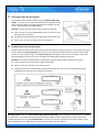
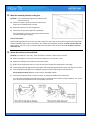
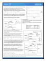
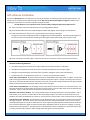
DRC 305‐A / July 2009
www.drivecam.com DC3 5‐Port HUB Installation with Universal Module How to install the DC3 Video Event Recorder (VER) through the 5‐Port HUB Connector with the optional GPS Antenna, Remote Trigger and/or Universal Module (UM05). Connection Diagram ........................................... 3 VER & HUB Installation (Start Here) ................... 4 DC3‐UM05 Power & Ground Connections ......... 7 UM05 Trigger Connections ............................... 11 GPS Antenna & Remote Trigger ................. 16‐17 Additional Information ..................................... 18 Hardware (ordered separately): Hardware (provided): DC3 Kit • DC3 Video Event Recorder • Windshield Mounting Bracket • Torx Screws (2); Torx Wrench; Alcohol Wipe 5‐Port HUB Kit • DriveCam 5‐Port HUB Connector with Cover • HUB Interconnect Cable (14 ft.) • HUB Power Cable (18 in.) Additional items you may need (not provided): •
•
•
•
•
Felt‐tip marker Voltmeter Wire cutter / crimper Wire connectors & extra wire (18 gauge) Flat blade screwdriver or panel removal tool GPS Kit • DriveCam GPS Antenna with Attached Cable (10 ft.) Remote Trigger Kit • DriveCam Remote Trigger (Pushbutton) • Pushbutton Collar • Pushbutton Cable (4½ ft.) Universal Module (UM05) Kit • UM05 • UM05 Interconnect Cable (18 in.) • UM05 Ignition Sense Cable (18 in.) • UM05 Switch Cable (6 wire bundle) Extended Mounting Bracket • Contact DriveCam for assistance with any issues related to how or where VERs should be mounted. Installation & How To Guides: Available online at: www.drivecam.com/Fleet/Documentation.aspx •
•
•
•
•
DriveCam Mounting Guidelines (DRC 340) DC3 Standard Installation Guide (DRC 303) DC3 5‐Port HUB Installation Guide (DRC 304) DC3 5‐Port HUB Installation with Universal Module (DRC 305) * This Document Additional information: product photos, descriptions, part numbers & ordering information. Copyright © 2009 DriveCam Inc. Safety Instructions
Read and follow the instructions and precautions in this book when installing components. Refer to the vehicle service manual for proper installation and wiring of aftermarket devices. Failure to do so may result in property damage and/or personal injury. This equipment is suitable for use in Class I, Division 2, Groups A, B, C and D or non‐hazardous locations only. WARNING – EXPLOSION HAZARD: Do not disconnect equipment unless power has been removed or the area is known to be non‐hazardous. WARNING – EXPLOSION HAZARD: Substitution of components may impair suitability for Class I, Division 2. Regulatory Information Adherence to Applicable Local, State and Federal Laws & Regulations Some jurisdictions have adopted, or may in the future adopt, laws that prohibit objects from being mounted on a vehicle’s windshield. For example, California, Minnesota, New Jersey and Florida currently prohibit or limit the mounting of objects, including DriveCam event recorders, on windshields. You are responsible for complying with any such laws, and DriveCam does not accept responsibility for your failure to do so. If you plan to operate your vehicle in a jurisdiction where windshield mounting is prohibited, contact DriveCam for assistance with any issues related to how or where VERs should be mounted. USA Federal Communications Commission (FCC) Notice This device complies with part 15 of the FCC Rules. Operation is subject to the following two conditions: (1) This device may not cause harmful interference, and (2) this device must accept any interference received, including interference that may cause undesired operation. Caution: Changes or modifications to this product not expressly approved by DriveCam Inc. could void the user's authority to operate this equipment. Note: This equipment has been tested and found to comply with the limits for a Class B digital device, pursuant to part 15 of the FCC Rules. These limits are designed to provide reasonable protection against harmful interference in a residential installation. This equipment generates, uses, and can radiate radio frequency energy and, if not installed and used in accordance with the instructions, may cause harmful interference to radio communications. However, there is no guarantee that interference will not occur in a particular installation. The FCC with its action in ET Docket 96‐8 has adopted a safety standard for human exposure to radio frequency (RF) electromagnetic energy emitted by FCC certified equipment. This device meets the Human Exposure limits found in OET Bulletin 65, 2001, and ANSI/IEEE C95.1, 1992. Proper operation of this radio according to the instructions found in this manual will result in exposure substantially below the FCC’s recommended limits. To comply with the FCC and ANSI C95.1 RF exposure limits, this device has been evaluated for compliance with FCC RF Exposure limits in the typical configuration. It is recommended that the antenna must not be co‐located or operating in conjunction with any other antenna or radio transmitter. During operation, the transmitter shall be separated at least 20cm (8 inches) from any human contact. Note: The radiated output power of this wireless device is far below the FCC radio frequency exposure limits. Nevertheless, this device should be used in such a manner that the potential for human contact during normal operation is minimized. Canada – Industry Canada Notice This device complies with Industry Canada RSS‐210 regulations. Operation is subject to the following two conditions: (1) This device may not cause harmful interference, and (2) this device must accept any interference received, including interference that may cause undesired operation. To prevent radio interference to the licensed service, this device must be operated indoors only and should be kept away from windows to provide maximum shielding. This Class B digital apparatus complies with Canadian ICES‐003.” Cet appareil numérique de la classe B est conforme à la norme NMB‐ 003 du Canada. Exposure of Humans to RF Fields The installer of this radio equipment must ensure that the antenna is located or pointed such that it does not emit RF field in excess of Health Canada limits for the general population; consult Safety Code 6, obtainable from Health Canada’s website: www.hc‐sc.gc.ca/rpb Declaration of Conformity: English
Hereby, DriveCam, Inc., declares that this DriveCamIII is in compliance with the essential requirements and other relevant provisions of Directive 1999/5/EC. The declaration of conformance is below.
Finnish
DriveCam, Inc. vakuuttaa täten että DriveCamIII tyyppinen laite on direktiivin 1999/5/EY oleellisten vaatimusten ja sitä koskevien direktiivin muiden ehtojen mukainen.
Dutch
Hierbij verklaart DriveCam, Inc. dat het toestel DriveCamIII in overeenstemming is met de essentiële eisen en de andere relevante bepalingen van richtlijn 1999/5/EG
Bij deze verklaart DriveCam, Inc. dat deze DriveCamIII voldoet aan de essentiële eisen en aan de overige relevante bepalingen van Richtlijn 1999/5/EC.
French
Par la présente DriveCam, Inc. déclare que l'appareil DriveCamIII est conforme aux exigences essentielles et aux autres dispositions pertinentes de la directive 1999/5/CE
Par la présente, DriveCam, Inc. déclare que ce DriveCamIII est conforme aux exigences essentielles et aux autres dispositions de la directive 1999/5/CE qui lui sont applicables
Swedish
Härmed intygar DriveCam, Inc. att denna DriveCamIII står I överensstämmelse med de väsentliga egenskapskrav och övriga relevanta bestämmelser som framgår av direktiv 1999/5/EG.
Danish
Undertegnede DriveCam, Inc. erklærer herved, at følgende udstyr DriveCamIII overholder de væsentlige krav og øvrige relevante krav i direktiv 1999/5/EF
German
Hiermit erklärt DriveCam, Inc., dass sich dieser/diese/dieses DriveCamIII in Übereinstimmung mit den grundlegenden Anforderungen und den anderen relevanten Vorschriften der Richtlinie 1999/5/EG
befindet". (BMWi)
Hiermit erklärt DriveCam, Inc. die Übereinstimmung des Gerätes DriveCamIII mit den grundlegenden Anforderungen und den anderen relevanten Festlegungen der Richtlinie 1999/5/EG. (Wien)
Greek
ΜΕ ΤΗΝ ΠΑΡΟΥΣΑ DriveCam, Inc. ΔΗΛΩΝΕΙ ΟΤΙ DriveCamIII ΣΥΜΜΟΡΦΩΝΕΤΑΙ ΠΡΟΣ ΤΙΣ ΟΥΣΙΩΔΕΙΣ ΑΠΑΙΤΗΣΕΙΣ ΚΑΙ ΤΙΣ ΛΟΙΠΕΣ ΣΧΕΤΙΚΕΣ ΔΙΑΤΑΞΕΙΣ ΤΗΣ ΟΔΗΓΙΑΣ 1999/5/ΕΚ
Italian
Con la presente DriveCam, Inc. dichiara che questo DriveCamIII è conforme ai requisiti essenziali ed alle altre disposizioni pertinenti stabilite dalla direttiva 1999/5/CE.
Spanish
Por medio de la presente DriveCam, Inc. declara que el DriveCamIII cumple con los requisitos esenciales y cualesquiera otras disposiciones aplicables o exigibles de la Directiva 1999/5/CE
Portuguese DriveCam, Inc. declara que este DriveCamIII está conforme com os requisitos essenciais e outras disposições da Directiva 1999/5/CE.
Suppliers Declaration of Conformity
We DriveCam hereby declare that the product listed below, to which this Declaration of Conformity relates, is in conformity with the Standards and other Normative Documents listed below:
Manufacturer’s Name & Address: DriveCam Inc. 8911 Balboa Ave., San Diego, CA 92123 USA Declares that the following product: Product Name: Video Event Recorder Product Model: DCIII The product specified above carries the marking, by complying with the essential requirements and provisions. Conformity is based upon the following standards Manufacturer’s Contact: DriveCam Inc. 8911 Balboa Ave. San Diego, CA 92123 USA Phone Number: (858) 430‐4000 Fax Number: (858) 430‐4001 Safety: IEC 60950‐1:2001; EN 60950‐1:2001 Low Voltage Directive 73/23/EEC EMC & Radio: CFR Title 47 FCC Part 15, Subpart B and C, Class B Industry Canada ICES‐003 Issue 4 (2004), Class B Industry Canada RSS‐Gen Issue 1 (2005) Industry Canada RSS‐210 Issue 6 (2005) EN 301 489‐1 v1.4.1 (2002‐08), RTTE Directive 1999/5/EC) EN 301 489‐17 v.1.2.1 (2002‐08), RTTE Directive 1999/5/EC) EN 300 328 v1.6.1 (2004‐11), RTTE Directive 1999/5/EC) EN55022: 1998 + A1: 2000 + A2: 2003 EN55024: 1998 + A1: 2001 + A2: 2003 EN61000‐3‐2: 2000 + A2: 2005 EN61000‐3‐3: 1995 + A1: 2001 Australia/New Zealand AS/NZS CISPR 22 (2006), Class B Australia/New Zealand AS/NZS 4771 (2000 + A1:2003) DriveCam strives to provide the most up‐to‐date information, however, products and their applicability may change periodically and, therefore, DriveCam makes no representation as to the accuracy of the information provided herein and assumes no obligation to update such information. DC3 5‐Port HUB Installation with Universal Module (305‐A) 2 DriveCam 5‐Port HUB with Universal Module Connection Diagram DC3 5‐Port HUB with Universal Module Installation The DC3, 5‐Port HUB and UM05 components below make up the main installation covered in this guide. The optional GPS Antenna and Remote Trigger may also be added to this installation (see notes below). DC3 Kit: • DC3 Video Event Recorder (VER) • Windshield Mounting Bracket • Torx Screws 5‐Port HUB Kit: • 5‐Port HUB Connector with Protective Cover • HUB Interconnect Cable (14 ft.) • HUB Power Cable (18 in.) ‐ Not Used with UM05 Universal Module (UM05) Kit: •
•
•
•
UM05 UM05 Interconnect Cable (18 in.) UM05 Ignition Sense Cable (18 in.) UM05 Switch Cable (6 wires) If you’re NOT installing the Universal Module, use the other DC3 5‐Port HUB Installation Guide (DRC 304). GPS Antenna : The GPS Cable plugs into the GPS Port on the HUB. See page 16 for installation instructions. • GPS Kit: DriveCam GPS Antenna with Attached Cable (10 ft.). Note: The GPS Antenna is not required for event recorder models configured with internal GPS receivers (page 18). Remote Trigger: The Pushbutton Cable plugs into the RT Port on the HUB. See page 17 for installation instructions. • Remote Trigger Kit: DriveCam Remote Trigger (Pushbutton), Pushbutton Collar & Pushbutton Cable (4½ ft.). Not e: UM05 installations typically use the UM05 Switch Cable for Remote Triggers instead (page 13). See page 18 for additional information DC3 5‐Port HUB Installation with Universal Module (305‐A) 3 1. Thoroughly clean and dry the glass The following steps describe installation using the Windshield Mounting Bracket. This is the most common installation method and applies to most sedans and light vehicles with sloped windshields and standard rear view mirrors. See note below for available options. CAUTION: This step is critical to prevent the bracket from falling off. A) Select a location on the windshield behind the rear view mirror on the passenger side of the vehicle. B) Using the alcohol wipe provided, thoroughly clean the mounting area. C) Using a clean, dry cloth, thoroughly dry the mounting area. 2. Carefully select a mounting location The VER needs to be mounted in a location that provides an unobstructed view of the interior and exterior (front) of the vehicle. Ideally, the interior‐facing lens should capture a view from the outside shoulder of the driver to the outside shoulder of a front seat passenger. The exterior‐facing lens should capture a clear view of everything in front of the vehicle, beginning as close to the front of the vehicle as possible without cutting off the horizon. CAUTION: An improperly positioned VER can significantly reduce the effectiveness of the DriveCam Program. A) Loosen the Torx screws so the VER can rotate in the bracket. B) Adjust or move the mirror down to its lowest position. C) Temporarily position the assembly (VER + bracket) behind the mirror, about one inch to the right of the post, providing access to the Torx screw and power connection. Mounting Options: Refer to the DriveCam Mounting Guidelines (DRC 340) if you’re installing in a vehicle without a standard rear view mirror. The document provides additional details and diagrams about VER mounting in various vehicle types, including instructions for using the Extended Bracket. Government restrictions regarding the mounting of objects on the vehicle windshield and U.S. Department of Transportation exemptions are also covered. DC3 5‐Port HUB Installation with Universal Module (305‐A) 4 3. Mark the mounting location on the glass CAUTION: Do not peel the backing from the adhesive strips until the next step. A) Hold the assembly in place and trace the outline of the bracket on the windshield with a marker. B) Remove the VER from the mounting bracket. C) Check the fit of the bracket against the windshield. If the windshield is curved, you may gently bend the bracket so it will lie flush against the glass. Final Location Check: Before attaching the bracket in the next step, take a moment to verify that you have selected a good mounting location. Hold the assembly in place and sit in the driver’s seat. Make sure the VER does not block the driver’s view of the road. Rotate mirrors, sun visors, wipers, and other objects near the VER to make sure those items do not block or interfere with either lens. 4. Attach the bracket to the windshield CAUTION: The adhesive is very sticky. Once the bracket is attached, it will not easily come off. A) Make sure the glass is clean and dry and the air temperature is at least 50°F (10°C). B) Remove the backing from the adhesive side of the bracket. C) Make sure the large plastic washer is on the left side of the bracket (see image below or next page). D) Start by placing the top edge of the bracket against the windshield, aligned with the marks, and make sure it’s level. E) Press the bracket firmly against the windshield starting at the top and pressing the sides downward. Do not apply excessive pressure as it may cause the windshield to break. F)
Check from outside the vehicle to make sure there are no large air bubbles under the bracket. You may need to (carefully) apply additional pressure to the bracket and remove any large air bubbles. Use a small pin to create an escape path for the air if the problem is persistent. DC3 5‐Port HUB Installation with Universal Module (305‐A) 5 5. Mount the VER in the bracket A) Plug the HUB Interconnect Cable (14 ft.) into the VER. B) Place the VER in the bracket. C) Adjust the VER so that it hangs vertically (plumb). D) Secure the VER in the bracket using the two Torx screws and Torx wrench (provided). Washer Placement: The large plastic washer on the left side of the bracket is designed to partially cover the cable connector so that it cannot be unplugged. The plastic washers can be easily removed from the metal bracket if you need to switch sides after mounting. Make sure the larger of the two washers is on the left side of the bracket. 6. Route the HUB Interconnect Cable You may need to remove the window and door trim to route the cable underneath. These typically snap on and off using special clips. In vehicles with side and curtain airbags, these clips are often one‐time use and may need to be replaced after removal. Please refer to the vehicle service manual for information. WARNING: When installing the cable in a vehicle with SIDE OR CURTAIN AIRBAGS, be certain that neither the cable nor your installation activities interferes with any airbag related mechanisms or otherwise risks affecting airbag deployment. A) Starting just above the rear view mirror, route the cable under the trim or headliner across to the door pillar. If you will be connecting the white wire from the UM05 Switch Cable to the dome light (page 11), you may want to route it along side the interconnect cable at this time as well. B) Route the cable down the door pillar underneath the vertical door/window trim then out under the lower part of the dashboard to the location where the 5‐Port HUB will be mounted and the electrical connections will be made. Secure the Cable: Make sure the cable is secured and cannot come loose. We recommend using cable ties every few inches along the route to secure it in place. Keep the cable clear of any sharp edges, moving parts and cannot get pinched in the door jam. Be very careful working around vehicle airbags. DC3 5‐Port HUB Installation with Universal Module (305‐A) 6 7. DC3 ‐ UM05 Power & Ground Connections The black, red and brown wires are the three required connections for the VER to function. The red wire provides primary power and must be connected to a continuous power source. The brown wire is an ignition‐sense, used by the VER to activate the IR Illuminator (page 18) when the vehicle ignition is switched on. The black wire is ground. A) Find a suitable location to make electrical connections (usually under the dashboard or vehicle electrical panel). B) Connect the wiring to the vehicle as described below. C) Plug the UM05 cables into the UM05 (see diagram on page 3). D) Test the connections in steps 9 and 10 before finalizing the connections. Connecting the RED WIRE to a 12V‐24V power source that is ALWAYS ON The VER requires a power source that is not controlled by the key nor any other device or switch. This connection is usually made just after the fuse box on the battery‐side of any vehicle control modules. Use a voltmeter to make sure the circuit provides continuous 12V or 24V power when the key is removed from the ignition and all lights, devices and switches are off. Test this connection in Step 9. Current Draw: If you’re tapping into an existing vehicle wire, make sure it can handle the additional current draw of the VER. A wire that reads 12V on a voltmeter may not necessarily be able to supply enough current to the existing circuit and the VER. The gauge of wire being tapped into provides a good indication. A larger gauge wire is often the best choice, but make sure to test it with a load. DC3 5‐Port HUB Installation with Universal Module (305‐A) 7 Connecting the BROWN WIRE to a 12V‐24V power source that is IGNITION‐SWITCHED This connection senses when the ignition is switched on. This requires a power source that is “on” only when the key is turned all the way forward to the “on” position and when the engine is running. It’s very important that this is connected properly. Test this connection in Step 10. Common Error: This connection is often (mistakenly) made to a modulated circuit – one that comes out of a computer control module running some subsystem in the vehicle – which can give false ignition on/off signals. To avoid this, make sure to connect this wire to a circuit that is on the battery side of any modules. Consult the vehicle wiring schematics or a local authorized dealership to obtain this information. Extending Wires If wires need to be extended, extend the ground wire first. If you must extend the red or brown wires, keep them as short as possible. If the extended length exceeds 16 inches, place an inline fuse (1‐3 Amp) between the extended wire and the power connection. The gauge of wire used for the extension must be the same gauge as the power cable wires or larger. Fuses The red and brown wires should be fused (3 Amp) to protect the circuit. If you don’t have inline fuses available, you can cut the fuses from the HUB Power Cable (since it’s not used for UM05 installations) and splice them onto the end of the UM05 cables. Electrical Wiring Connectors Due to the variety of preferred wiring methods (ring terminals, splice connectors, fuse taps, poke‐n‐wrap), electrical connectors are not included in the hardware kit. Refer to the vehicle service manual for information about installation and wiring of aftermarket devices. We highly recommend this installation be completed by a qualified automotive electrician. DC3 5‐Port HUB Installation with Universal Module (305‐A) 8 8. Connections to the 5‐Port HUB The 5‐Port HUB has a silicone shell that covers the ports and cable connectors, protecting them from corrosion and damage. We recommend using the shell with all installations. We also recommend applying dielectric grease to all cable connectors before plugging them into the HUB. A) Remove the shell from the HUB. Refer to the connection diagram on page 3 to determine which cables plug into which ports on the HUB. B) Cut about 1/8 to 1/4 inch from the tip of the shell sleeve above the following ports on the HUB: • Camera Port ‐ HUB Interconnect Cable • Battery Port ‐ UM05 Ignition Sense Cable • UM/RT Port ‐ UM05 Interconnect Cable The sleeve should fit tightly around each cable to ensure maximum protection from corrosion. The smaller opening, however, may make it difficult to push the cable connectors through. The silicone sleeves will stretch, but you may need to apply a lubricant (such as dielectric grease) to the connectors, allowing them to slip through more easily. C) Press the sleeves down through the shell (invert them inside‐out). D) Push the HUB Interconnect Cable, UM05 Ignition Sense Cable and UM05 Interconnect Cable through the inverted sleeves until they poke through the other side. See notes below. E) Pull the sleeves back up through the shell. F)
Plug the cables to the HUB. G) Proceed to the next page to test the connections. Note: If you’re planning to install the GPS Antenna (page 16) and/or Remote Trigger (page 17), you may connect those cables into the HUB at this time as well. Repeat the steps above for the GPS and/or RT Ports on the HUB. DC3 5‐Port HUB Installation with Universal Module (305‐A) 9 8. Test the RED WIRE connection (continuous power) Once the power and ground connections are made and the vehicle ignition is switched on, the status light to the right of the interior‐facing lens should be lit (either a red or green light). Note: VERs are configured for hibernation mode, meaning it will automatically switch off (status lights will go dark) after the vehicle ignition has been off for a certain amount of time (15 minutes – several hours). Switch on the vehicle ignition or press one of the VER buttons to “wake up” the VER from hibernation. See page 18 for more information. A) Wait about 30 seconds after connecting power (red) and ground (black). B) Turn the key to the Ignition / Switched‐On position. The status light to the left of the lens will light solid green for about 30 seconds after power is first applied and then switch OFF. The status light to the right of the lens should then switch ON and stay on (see note above). Other status light behaviors that are commonly seen:
• Left light blinking green: Searching for a wireless signal. • Right light blinking red: Data transfer in progress. • Right light blinking red & green: Event recording in progress. • Both lights blinking red & green: Firmware upgrade in progress. C) These behaviors may continue for several minutes. All of them indicate that the VER is properly powered. Go to step 9. Errors: If the status lights did not light at all, check the wiring and fuses. If you see any other status light behaviors, contact DriveCam Technical Support at (866) 910‐0403. 9. Test the BROWN WIRE connection (ignition‐switched power) Underneath the translucent cover surrounding the interior‐facing lens are six small, infrared lights. These are the VER’s Infrared (IR) Illuminators, providing infrared light for recording video in low light situations. These lights can only be seen when they are lit, and they are only lit when power is being sensed through the brown wire (i.e. when the engine is running or when the key is turned all the way forward to the ignition ON position). A) Turn the key to the Ignition / Switched‐On position. B) Look closely for the six red lights underneath the translucent cover. C) Turn the key to the OFF position. The six red lights should go out. D) If the test worked as described, the brown wire has been connected properly. Go to the next page. If the test did not work as described, try it again in a darker area or cup your hands around the cover; the lights can be difficult to see. Next, check the wiring and fuses. It may have been connected to a modulated circuit (page 8). DC3 5‐Port HUB Installation with Universal Module (305‐A) 10 UM05 Trigger Connections DriveCam’s Universal Module (UM05) provides multiple input and output connections, allowing you to configure the VER to record events through a variety of additional methods (doors, switch, taxi meter, horn, alarm, lights, others). The output enables the VER to control other devices in the vehicle. The Universal Module is typically used in passenger carrying vehicles as part of DriveCam’s Safety Enhancement Mode (SEM). UM05 Switch Cable: White Wire Connections The Primary Trigger Input (White Wire) is typically set up to monitor the vehicle’s doors. The VER will then record an event each time a door is opened or closed. Tip: In many cases, the dome light circuit is the best place to make this connection as it is usually connected to all of the vehicle’s doors. Some vehicles use a common door switch circuit (connecting all doors and the dome light) while other vehicles use an individual door switch circuit (connecting each door to a controller and the controller to the dome light). Refer to the vehicle wiring schematics for information. If you can find the dome light circuit under the dashboard, you won’t have to route the wire up to the dome light. If not, simply make the connection at the dome light (described here). Before making the connection, you must first determine the type of bulb circuit (switched power or switched ground) and make the appropriate primary (PRI) switch settings on the UM05. Determine the circuit type (for connections at the dome light): A) Remove the dome light cover, leaving the bulb in place. B) Turn the load OFF (close all doors to turn off the dome light). C) Measure the voltage at either of the bulb terminals. D) Set the PRI switch on the UM05 as described in this image. >> Determine where to make the connection: A) Turn the load ON (open a door to turn on the dome light). B) Measure the voltage at each of the bulb terminals. One terminal voltage will remain the same as measured in step C – the other terminal voltage will have changed. The white wire must be connected to the terminal that changed voltage. DC3 5‐Port HUB Installation with Universal Module (305‐A) 11 Connecting the White Wire The best place to keep the UM05 is usually under the dashboard. This requires several feet of the white wire routed up the window trim (typically alongside the HUB Interconnect Cable) then under the headliner to the dome light. See page 6 for information about routing wires. A) Unscrew the dome light fixture from the ceiling to expose its wiring and provide an entry point under the headliner. B) Route white wire from the location where you will mount the UM05 (e.g. under the dashboard) to the dome light. A coat hanger can often be used to “hook and pull” the wire under the headliner. C) Connect the white wire to the dome light. Make sure you are connecting to the correct side of the dome light circuit as measured above (i.e. the terminal that changed voltage). CAUTION: You may need to remove the window and door trim to route the wire underneath. These typically snap on and off using special clips. In vehicles with side and curtain airbags, the clips are often one‐time use and may need to be replaced after removal. Please refer to the vehicle service manual for information. WARNING: When installing the cable in a vehicle with side or curtain airbags, be certain that neither the cable nor your installation activities interferes with any airbag related mechanisms or otherwise risks affecting airbag deployment. Testing the Connection: Use the green light on the top of the UM05 to test the connection. A) Open a vehicle door. The test light should be lit (solid green). B) Close all vehicle doors. The test light should go out (at the same time as the dome light). • If the test worked as described, the primary trigger input is functioning correctly. Continue to the next section. • If the UM05 Test Light was reversed (i.e. lit when the doors were closed and off when a door was opened) then the primary (PRI) switch setting on the UM05 is incorrect. Change the switch setting and repeat the test. • If the UM05 Test Light did not light at all, check the power, ground, and primary wire connections. DC3 5‐Port HUB Installation with Universal Module (305‐A) 12 UM05 Switch Cable: Orange Wire Connections The Secondary Trigger Input (Orange Wire) can be connected to one of several different electronic devices in the vehicle (e.g. taxi meter, car alarm, horn, button or switch). The VER will then record an event each time the device is activated. In most cases, it is connected to a concealed switch that can be manually triggered by the driver in an emergency. Most standard constant state switches (toggles; push on/push off) or momentary pushbuttons may be used. Before making the connection, you must first determine the type of circuit (switched power or switched ground) and make the appropriate secondary (SEC) switch settings on the UM05. Determine the circuit type (for connections to a switch): A) Install the switch. B) Turn the switch ON. C) Measure the voltage at either of the switch terminals. D) Set the SEC switch on the UM05 as described in this image. >> Determine where to make the connection: A) Turn the switch OFF. B) Measure the voltage at each of the switch terminals. One terminal voltage will remain the same as measured in step C – the other terminal voltage will have changed. The orange wire must be connected to the terminal that changed voltage. Connecting the Orange Wire A) Connect the orange wire to the switch. Make sure you are connecting to the correct side of the circuit as measured above (i.e. the terminal that changed voltage). Testing the Connection: Use the green light on the top of the UM05 to test the connection. A) Close all vehicle doors and wait about one minute. B) Turn (or press) the secondary switch “ON”. The test light should light for about two seconds before going out. If you’re using a momentary pushbutton (press ON / release OFF), press and hold the button for this step (B) then release the button for the next step (C). C) Turn (or press) the secondary switch “OFF”. There should be no indication from the test light. • If the test worked as described, the secondary trigger input is functioning correctly. Continue to the section below. • If the UM05 Test Light did not light when the switch was turned “ON” then the secondary (SEC) switch setting on the UM05 is incorrect. Change the switch setting and repeat the test. • If the UM05 Test Light did not light at all, check the power, ground, secondary wire, and switch connections. If this is all you’re planning to install, proceed to page 18 to finish up. •
•
•
UM05 Output Connections are described on pages 14‐15. GPS Antenna Installation is on page 16 Remote Pushbutton Installation is on page 17. DC3 5‐Port HUB Installation with Universal Module (305‐A) 13 Using the UM05 Output Feature (Blue & Yellow Wires) ‐ Optional The DC3 Video Event Recorder (VER) has the ability to control other devices within the vehicle. The VER has an output signal that will change from its normal state whenever an event is triggered. After saving that event, the output returns to its normal state. With the UM05 device, this function is greatly enhanced. The user has the ability to determine the voltage level of the output as well as whether the output’s normal state is high or low. The output can provide TTL level logic signals, or it can be used to operate loads drawing up to 2 Amperes of current. These loads can be either resistive (lights) or inductive (relays or motors). Due to the wide variety of ways that this output may be used, it is impossible to cover all potential applications. The instructions and examples contained here should be considered a general guide. Your particular application will determine the actual wiring configuration. NOTE: Due to variety of ways the Output feature may be used, we recommend that wiring be done by a qualified automotive electrician. CAUTION: Although every effort has been made to prevent it, incorrect wiring of the Output feature may cause damage to your UM05. General Operation The Output feature of the UM05 acts like a switch. One side of this switch is permanently connected to the black wire (ground) of the UM05 switch cable. The other side of the switch is connected to the blue wire. Also connected to the blue wire is a 1,800 Ohm (1.8KΩ) resistor whose opposite side is connected to the yellow wire. This yellow wire needs to be wired to a voltage source if you want the voltage at the blue wire to go up when the switch is open. Figure 1 shows a block diagram of the UM05 output circuit. If the OUT switch on the UM05 is set to NORM LO, the output switch will be closed all the time unless an event has been triggered in the VER. When an event is triggered, the output switch will open while the VER is recording and saving the event. When that is complete, the switch will close again. If the OUT switch is set to NORM HI the switch will work in the opposite way (i.e. open normally, closed when an event is triggered). It should be noted that the switch can also change states if the voltage to the VER drops below 9 Volts. When this happens the switch will behave the same as if there was an event on the VER. If the OUT switch on the UM05 is set to NORM LO, the output switch will be closed all the time unless an event has been triggered in the VER. When an event is triggered, the output switch will open while the VER is recording and saving the event. When that is complete, the switch will close again. If the OUT switch is set to NORM HI the switch will work in the opposite way (i.e. open normally, closed when an event is triggered). It should be noted that the switch can also change states if the voltage to the VER drops below 9 Volts. When this happens the switch will behave the same as if there was an event on the VER. Wiring Options There are many ways the output of the UM05 can be used. The following section shows some sample applications. Your particular application will determine the actual wiring configuration. These examples should only be considered a general guide. Example 1: Triggering a secondary electronic device Generally, it is very easy to connect your UM05 to trigger a secondary electronic device. These types of devices typically require voltage levels but very low current. The yellow wire is connected to +12V so that the voltage at the blue wire will go up whenever the switch opens. When the switch is closed the voltage at the blue wire will be low. The yellow wire can be tied to a constant or switched voltage source. When tied to a constant voltage source there will be approximately 0.007A (7mA) of current drawn at all times. If the yellow wire is tied to a switched voltage source, the voltage at the blue wire will never go up when the switched voltage source (i.e. ignition switch) is off. Table 1 shows the UM05’s approximate output level of the blue wire for a VER during an event or during normal, non‐event operation. If the GPS requires the voltage to go high to trigger it, set the UM05’s OUT switch to NORM LO. If the GPS requires the voltage to go low to trigger, set the switch to NORM HI. If the GPS setting is selectable a NORM LO setting should typically be used. NOTE: With the yellow (supply) wire connected to a switched voltage source and the UM05’s OUT switch set to NORM HI, the blue wire will go low whenever the voltage is turned off even though there is no event. If the electronic device requires a voltage other than the normal vehicle voltage (i.e. a +5V level) and that voltage is available at the device, simply connect the yellow wire to the voltage source. DC3 5‐Port HUB Installation with Universal Module (305‐A) 14 For applications like those shown in example 1, it is important to realize that the ability to supply current from the blue (output) wire to a device is limited. How much current can be drawn from the wire is dependent on the voltage necessary at the wire. Figure 4 shows the relationship of voltage at the blue (output) wire vs. current being drawn for 12 Volts and 5 Volts at the yellow (supply) wire. Normally, electronic devices with signal inputs require very little current so the voltage supplied to them by the blue wire will be very close to the voltage supplied to the yellow wire. Example 2: Triggering devices that use up to 2 Amps and have a separate ground wire There are many auxiliary devices for vehicles that fit into this category. Auxiliary lights, warning buzzers, and relays are some of the possible devices. If the total current draw is less than 2 Amps and the device has a separate ground wire (not chassis grounded) this method can be used. In this situation, the yellow supply wire is not used. Instead the device to be operated has its positive wire connected to a +12 Volt source and the negative wire is connected to the blue wire as shown in figure 5. In example 2, because we are switching the ground wire, operation of the device may seem backwards. To turn the device ON we need the UM05 switch to turn ON which will make the voltage at the blue wire go LOW. Table 2 shows how to set the UM05 OUT switch to achieve the desired function at the load. Example 3: Triggering heavy current or chassis ground devices Example 3 is actually very much like example 2, but the load that is operated by the UM05 is a relay. This configuration is used if the load current of the device is greater than 2 Amps, or if the device has a chassis ground (no separate ground wire). The UM05 OUT switch settings for this example, a Normally Open (NO) relay, are those shown in table 2. If a Normally closed (NC) relay were used the table would be reversed. Example 4: Triggering a secondary electronic device that needs more drive current In some rare cases, the UM05 may be connected as shown in example 1, but there is not enough current supplied by the UM05 to drive the input. The drive current may be increased by duplicating the job of the UM05’s internal supply resistor with an external one (see figure 7). If this is done, three precautions must be adhered to: First, the current through the resistor must be 2 Amps or less. For a 12 Volt electrical system this means the resistor should be greater than 8 Ohms. To prevent other problems, the resistor value should be as high as possible and still pass the current needed for the application. Second, the resistor will have to be able to handle the wattage dissipated by being connected to ground. For that 8 Ohm resistor on a 12 Volt system the wattage rating of the resistor should be above 30 Watts. Third, the current in this example could be high enough to cause a serious drain on the vehicle battery. The 12V to the external resistor should be switched off with the ignition switch, or the blue line should not be configured so that it is normally low when the ignition switch is off. Example 5: Linking two or more VERs in series Multiple VERs can be connected in series so that when one is triggered, all will be triggered. Contact DriveCam for detailed instructions. NOTE: Anyone attempting a type of installation like example 4 or 5 should have a thorough understanding of electrical systems and electricity. Incorrect implementation of this could damage the UM05 and/or create a fire hazard for the vehicle. DC3 5‐Port HUB Installation with Universal Module (305‐A) 15 GPS Antenna Installation DriveCam’s GPS Antenna must be mounted in an area of the vehicle that receives good GPS satellite signal reception. The antenna has an attached 10 foot cable that plugs into the GPS Port on the HUB (see diagram on page 3). Make sure the mounting location allows for connection and easy routing of the cable. The GPS Antenna is not required for event recorder modules configured with internal GPS receivers A) Select a location to mount the GPS Antenna (see mounting guidelines below). B) Route the GPS Cable to the 5‐Port HUB, through the rubber shell (page 9) and then plug it into the GPS Port. C) Test the GPS Antenna to make sure it’s in a good location and receiving a GPS signal: The light on the antenna will blink (red) after it is plugged into the HUB and powered. It will blink slowly (about one second on and one second off) when searching for a GPS signal and then blink rapidly when a signal is found. D) Secure the antenna and cable in place. Make sure the cable is secured out of the way and will not come loose. GPS Antenna Mounting Guidelines • The ideal mounting location allows line‐of‐sight reception from the GPS satellites in orbit above. • GPS signals will not penetrate metals of any kind. Coated (tinted) windows may also block signals. • GPS signals will penetrate glass (uncoated), plastic, Styrofoam, fiberglass, wood, carpet and upholstery. • The GPS Antenna is not designed for external use – it must be mounted inside the vehicle. On the top of the dashboard: Secure the GPS Antenna flat on the dashboard with tape, Velcro, or magnet. Tuck the GPS Cable into the gap between the dashboard and the windshield (wrap with tape for a snug fit if necessary) then route the cable across and under the dashboard for connection to the HUB. This location usually provides the best signal reception. Make sure the GPS Antenna is positioned under a clear section of the glass. On the front of the dashboard: Use the magnet on the back of the GPS Antenna to attach it to a flat metal surface. The GPS Cable should be secured just below the antenna to keep it in place. Route the cable neatly under the dashboard for connection. Velcro or tape may also be used to secure the antenna in place. Attached to the inside of a window: Use a strong adhesive tape to attach the GPS Antenna to the windshield, a side or back window, or the sunroof. The GPS Cable can be routed along the edge if the window or tucked under the trim or headliner then under the dashboard for connection. Do not place the antenna under a dark or tinted section of the glass. Concealed under the dashboard: The GPS Antenna can be placed under any non‐metal object and still receive excellent GPS signal reception. This means you can mount the antenna directly under the dashboard, on an air vent, or under a removable plastic panel or trim piece. Make sure there are no large metal pieces between the GPS Antenna and the sky. Even small metal brackets or pipes can deteriorate the signal, depending on the size of the holes, openings, or spacing between the metal components. The upper portion of the dashboard is often an ideal place to conceal the antenna as it is usually composed only of plastic or foam, through which GPS signals can easily penetrate. DC3 5‐Port HUB Installation with Universal Module (305‐A) 16 Remote Trigger Installation DriveCam’s Remote Trigger enables drivers to trigger Remote Manual Event recordings through a conveniently mounted button. The button comes with a 4½ foot cable that plugs into the RT Port on the HUB (see diagram on page 3). Make sure the mounting location allows for connection and easy routing of the cable. Note: Universal Module installations do not typically use the setup below for Remote Triggers. Instead, a button or switch is connected through the UM05 Switch Cable’s White or Orange input wires. Use the procedures below to install the button and connect the cable to the RT Port on the HUB if you want to record “Remote Manual Events” instead of “Safety Events” through the Universal Module. Contact DriveCam Technical Support for additional information. A) Select a location to mount the button. The button is designed to be mounted in a fixed panel. It should be a location where the driver will not have to reach to press the button. Nor should it be placed where the driver may accidentally press the button. The Pushbutton Collar (see below) may be fitted over the button to help prevent accidental triggers. This is optional. B) Using the proper bit size (about 1 inch), drill a hole into the panel. The button mounting hole diameter must be between 15/16 – 17/16” (24 – 27 mm) and the panel thickness between 1/32 – 1/8” (1 – 3 mm), which is about the thickness of a nickel. It can be installed in a thicker panel but the button will not snap into place. C) Route the Pushbutton Cable through the hole and connect the two wires to the tabs on the bottom of the button. It does not matter which tab the wires are connected. D) Route the other end of the cable to the 5‐Port HUB, through the rubber shell (page 9) and then plug it into the RT Port. E) Verify correct operation by pressing and releasing the button to trigger an event recording. The right status light on the VER should begin to flash for several seconds. If not, recheck the wiring. F) Following verification, press the button firmly into the mounting hole. Note: If needed, a second Remote Trigger may be installed and plugged into the UM/RT Port on the HUB. Mounting the Pushbutton Collar (optional): Adhesive tape on the bottom of the collar holds it in place. Make sure to clean the mounting surface thoroughly before attaching the adhesive collar. The tabs around the ring may be trimmed off if space is needed or to provide a better appearance. We recommend keeping at least 2 tabs on the collar. DC3 5‐Port HUB Installation with Universal Module (305‐A) 17 Installation Complete Follow these steps to finish up: A) Make sure the cables are tucked safely under the trim and cannot get pinched in the door jam or any moving parts. B) Reaffirm that you have taken the appropriate safety precautions while working around vehicle airbags. C) Finalize all electrical connections. Use cable‐ties to bundle and secure all wires so they don’t come loose. D) Make a note of the VER serial number and the vehicle in which it is installed. Provide this to management. E) Keep the Torx wrench and this guide in a safe place for future use. The DriveCam‐equipped vehicle is ready to be placed in‐service with the DriveCam Program. Additional Information DriveCam Technical Support is available 24 hours / 7 days at (866) 910‐0403. For international assistance please call (858) 380‐3007. Or, email questions to [email protected] Installation & How To Guides: Available online at: www.drivecam.com/Fleet/Documentation.aspx A) GPS‐enabled VERs: Some (newer) models of the DC3 Video Event Recorder are configured with internal GPS receivers, capturing GPS data with every event recording and without the need to install the external GPS Antenna (page 16). GPS‐enabled VERs have a model number ending in “CP” printed on their label. Contact DriveCam Technical Support if you’re not sure which VER model you have. B) Mounting Options: There are alternate mounting options available for the VER. The Standard Windshield Mounting Bracket positioned behind the rear view mirror (as described in this guide) is the most commonly used and typically provides the best solution. However, the Extended Bracket provides a wide variety of mounting locations, particularly in larger vehicles or vehicles without a standard rear view mirror. Refer to the DriveCam Mounting Guidelines (DRC 340) document for detailed information and mounting information. C) Hibernation Mode: A feature of the VER which allows it to enter a low power state in order to conserve vehicle battery power. The VER will “hibernate” if it does not sense an ignition for a certain amount of time. Hibernation settings are chosen by the client and range from 15 minutes after ignition cut‐off to 4, 8, 12, 18, 60 hours or never hibernate. All status lights will go dark during hibernation. To “wake up” a VER from hibernation, switch on the vehicle ignition or press one of the buttons on the bottom of the VER. D) Infrared (IR) Illuminator: Lights the interior of the vehicle with infrared light (invisible to the eye), enabling the VER to record clearly lit images in low light situations. This draws additional power from the vehicle, which is why it switches on and off with the vehicle ignition. The brown wire on the power cable provides this switch and must be connected to an ignition‐switched power source. E) Serial Number: Each VER is labeled with a unique 8‐digit serial number, used to identify the VER and the vehicle in which it is installed. The serial number (SN:) is printed on a small label on the back or side, just above the bar code. Example: “SN: ER00092D” F)
Operating Specifications: The input voltage is 12V to 24V DC (9V min to 30V max). The operating temperature is ‐40 to 185 °F (‐40 to 85 °C). A full list of specifications is available from DriveCam. End of document. DC3 5‐Port HUB Installation with Universal Module (305‐A) 18


![日本語 [Rev 1.00] - ViTiny マイクロスコープ](http://vs1.manualzilla.com/store/data/006555709_3-84b0277bd17a0b700047e713a429bb8f-150x150.png)