1
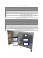
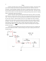
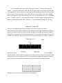
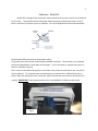
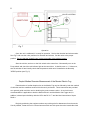
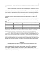
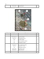
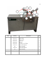
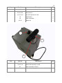
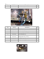
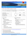
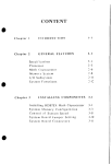
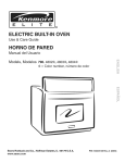
MOZZIE
ELECTRIC FOG
OWNER'S MANUAL
MODELS 200-250
55-73-0200
© 2004 ARRO-GUN SPRAY SYSTEMS
040505
2
TABLE OF CONTENTS
PAGE
Specifications
Setup
Electrical Test
3
3-4
5
Calibration
6-7
Operation
7-8
Droplet Median Diameter Measurement
8-9
Maintenance
Parts
How to Order Parts
9
10-16
16
3
Specifications - Model 200
Dimensions
Weight
Cemical Tank
Pump
Pump Flow Rate
Voltage
Full Load Amperage
Recommended Battery
Recommended Alternator
42" W x 21"D x 40" H
107cm W x 53cm D x 102 cm H
Net:
Gross:
Net:
Gross:
4 Gallon Max Capacity HDPE
12 VDC FMI Type RHB
8.5 OPM Max, 1 - 6 OPM Recommended
12 Volts DC Nominal, 12.5 - 13.2 w/charge
80-85 Amperes
Group 27 Deep Cycle Marine or
Optima Yellow Top Gel Cell SC34DU
Minimum 135 Amp, Heavy Duty or High Output Recommended
Note Vehicle Model, Year, Engine Type
Specifications - Model 250
Dimensions
Weight
Chemical Tank
Pump
Pump Flow Rate
Voltage Input
Voltage Output
Full Load Amperage DC
Full Load Amperage AC
Recommended Battery
Recommended Alternator
42" W x 21"D x 40" H
107cm W x 53cm D x 102 cm H
Net: 170 Gross: 220
Net: 77.2 Kg
Gross: 99.9 Kg
6 Gallon Max Capacity HDPE, Fully Enclosed
12 VDC FMI Type QB1
1-19 OPM Max, 1 - 12 OPM Recommended
12 Volts DC Nominal, 12.5 - 13.2 w/charge
115 V a.c. Modified Sine
85-90 Amperes
10-11.5 Amps
Optima Yellow Top Gel Cell SC34DU (Included)
Minimum 135 Amp, Heavy Duty continuousor High Output
Recommended Note Vehicle Model, Year, Engine Type
Larvicide
Hopper
Connection
Control Box
Receptacle
Ground
Cable Thru
Hole
Main Power
Cable
Fig.1
4
Setup
Packed in the cabinet are the control box, nozzle(s) with quick couplings, a main power cable,
ground cable, and high output alternator (if supplied) as required for the vehicle the unit will be
mounted to. Have the alternator installed to the vehicle by a qualified mechanic. Position the unit to
the truck bed and if desired, bolt the skids to the truck or secure by other means. Take care to check
ground of the unit frame to the vehicle frame and if necessary provide ground by means of a bonding
strap or 4 AWG battery cable with terminal lugs.
Install the main power cable by attaching the terminal end to the plus (+) BAT or B+ terminal
of the alternator. Route the cable so that it is clear of any moving parts and secure along the vehicle
frame. Connect the cable to the unit by firmly pushing into receptacle until the weather door latches
the rear of the connector. Install the battery into the unit if not supplied and connect the battery
cables provided. Red connects to positive terminal of the battery, black to the negative terminal of
the battery. On Model 250 a separate short black ground cable is provided with a plastic bushing.
Install cable by routing through hole in back of cabinet, and squeeze bushing to snap in place.
Ground the black cable to a good vehicle frame ground. Install the remaining end to the negative
terminal of the battery.
Connect the 4-pole plug (Model 200 only) from the control box firmly into the receptacle and
push until the weather door latches. Install the nozzle(s) into the quick coupler(s) and connect the
insecticide line(s).
Battery
MODEL 200
12 Vdc
Alternator
B+
BATT
+
Main
Cable
Fig. 2
100 A
Circuit Breaker
Unit
Battery
5
IMPORTANT: BEFORE THE UNIT IS OPERATED FOR THE FIRST TIME
THE BATTERY MUST BE FULLY CHARGED. PLACE THE BATTERY
ON A MINIMUM 6-10 AMP CHARGER CAPABLE OF TRICKLE
CHARGE MAINTENANCE AND CHARGE A MINIMUM OF 12 HOURS.
DO NOT USE THE VEHICLE ALTERNATOR TO CHARGE A LOW
BATTERY.
Battery
Alternator
MODEL 250
12 Vdc~115 Vac
B+
BATT
+
Unit
Battery
Main
Cable
200 A
Contactor
Fig. 3
Blower
Inverter
Electrical Test - Model 200
With the unit completely connected, start the vehicle and run at idle. Turn the Unit switch on
the control box to the "ON" position. With a DC multimeter check the voltage across the battery
terminals of the unit. You should read 12.7 + volts on the meter. If available, check the current draw
with a clamp-on ammeter capable of reading AC/DC true RMS such as a Wavetek AD105 Cat.III
1000 Amp. You should obtain a reading of 80-85 Amps.
Electrical Test - Model 250
The test of the Model 250 is slightly different from the 12 volt model. Once all the cables have
been installed, connect the control box at the 7 pin cannon plug. Unplug the blower from the
inverter. Turn the unit swith on the control box to the "ON" position. You should hear the contactor
energize. Now turn the inverter on at the switch provide on the front panel. A green indicator light
should come on and you will hear a slight whistle as the internal capacitors of the inverter charge.
6
Use a small load electric drill or light to plug into the inverter. The drill or light should run
normally. Turn the unit switch on the control box off. The green light on the inverter will slowly fade
until completely off. Now reconnect the blower. With the unit completely connected, start the vehicle
and run at idle. Turn the Unit switch on the control box to the "ON" position. With a DC multimeter
check the voltage across the battery terminals of the unit. You should read 12.5-12.7 + volts on the
meter. If available, check the current draw with a clamp-on ammeter capable of reading AC/DC true
RMS such as a Wavetek AD105 Cat.III 1000 Amp. You should obtain a reading of 87-90 Amps.
Calibration - Model 200
The pump was calibrated at the factory to dispense 4 oz/minute of mineral oil. Due to
voltage variations from vehicle to vehicle, a slight adjustment at the pump control may be needed to
fine tune the chemical system for proper flow rate. To adjust the flow rate, be sure that the Mozzie
Electric Fog is connected to the vehicle charging system. Fill the chemical tank about half full of the
chemical to be used. Disconnect the chemical line at the nozzle and place in a suitable container or
Pump set at 1.2
Fig.4
route back to the tank. See p.8 to set the proper valve position. Turn the pump switch ON and
allow the system to fill with fluid. Run the pump until all air is purged from the pump and valve. When
all air has been removed, transfer the fluid line into a graduated cylinder and measure the fluid flow
for two minutes. Set the approximate desired flow rate of the pump by referring to the table:
Pump Setting
1.25
2.2
3.15
4
Rate OPM
2
4
6
8.45
With the pump set, reconnect the insecticide line to the nozzle.
7
Calibration - Model 250
Model 250 is equipped with a pressure switch located at the top of the motor unit just behind
the air outlet.
The pressure switch controls the chemical pump by switching the pump on only if
there is sufficient air pressure on the air manifold. The unit is shipped with the wire tab attached to
Normally
OPEN
COMMON
Normally
CLOSED
Fig.5
the Normally OPEN connection at the pressure switch.
Temporarily move the wire tab to the Normally CLOSED connection. This will allow you to calibrate
the pump independently of other parts of the system. It is not necessary to operate the inverter or
blower to calibrate the pump.
Now loosen the knurled knobs slightly on each side of the pointer of the pump so that the pointer
can be adjusted. Turn the black knob counterclockwise to increase flow. Measure flow rate as
above. When the desired flow rate is achieved, tighten knurled nuts and reconnect chemical line to
nozzles. IMPORTANT Reset pressure switch wire to the NORMALLY OPEN connection tab.
Fig.6
8
VALVE LOCATION
INSECTICIDE
SOLVENT
Fig. 7
Operation
Once the unit is calibrated, it is ready for operation. Service the chemical and solvent tanks.
See Fig.7 and note the valve positions for chemical and solvent. Set the valve to the proper
position. Be sure that the "butterfly vent" on the motor side of the cabinet is open.
Start the vehicle, and turn on the Unit switch at the control box. Momentarily turn on the
Pump switch and check the red indicator light at the control box. It should come on. If it does not,
turn all switches off and visually check that the pressure switch wire is installed to the Normally
"OPEN" position (see Fig. 5).
Droplet Median Diameter Measurement of the Mozzie Electric Fog
Determination of median droplet size on the Mozzie Fog can be affected by both the method
of collection and the conditions under which the test is performed. These instructions are provided
as a general guide to aid the user in obtaining the most accurate results. As a rule this test
recommendation is applicable to both the Mozzie Electric and the Mozzie Gas Fogger and, in
addition, is based upon familiarity with the KLD Labs DC-III ™ and the label instructions of AquaReslin ®.
Begin by positioning the equipment where any existing wind is downstream from the nozzle.
If at all possible, locate the unit in a closed structure with one side open where the insecticide cloud
9
will exhaust outdoors. Mix the Aqua-Reslin in the ratio planned for treatment, and place in insecticide
tank.
Operate the unit and, with a anemometer, find the point at which the nozzle velocity reads 33.5 meters/second (on the Mozzie Electric this is approximately 36"-42" from the nozzle). Although
KLD Labs instructions state that velocity should be read at 5-7 meters/second for most testing, the
point at which that reading occurs is within an area where the particles are still being sheared by the
Mozzie nozzle due to the characteristics of the nozzle design. In consultation with KLD Labs it was
recommended not to test lower than 3 meters/second. We have determined that the 3-3.5 range
would satisfy the limits of the analyzer and return an accurate representation of the particle size
spectrum.
Once all preparation has been made, run a 30 second or 60 second test with the DCIII set to
analyze oil. Results obtained with Aqua-Reslin on the Model 200 should compare to the following
table:
Aqua-Reslin Mix
Pump Setting
MMD
Neat
Flow Rate
oz/min
1.68
1.10
22-23
1+1
2.10
1.25
24-25
1+2
3.10
1.60
26-27
As a basis for comparison, plain water run at 3.1 opm and a velocity of 3.5 meters/sec yields a 42-44
mmd spectrum. It follows that the more dilute the mixture is, the higher the shift in droplet median
diameter, therefore, we do not recommend dilutions higher than 2+1 of water to Aqua-Reslin.
Another important aspect of the results returned by the DC-III is the total droplet count. In
our experience, a probe in good condition should indicate total droplet counts of 2500-3500 in a one
minute run and roughly 1/2 of those totals in a 30 second run. Significantly lower counts than these
might indicate a probe in poor condition or not in the correct position. In this instance, reverify the
velocity at the point where the probe is placed within the fog. In addition, when taking readings move
the probe slowly across the fog pattern, being careful to keep the probe perpendicular to the cloud.
Maintenance
Maintenance on the Mozzie Electric is routinely simple. Once a month check the cable
terminations at the battery and clean if needed. Check all chemical tubing for wear and tear and
replace if needed. Keep the chemical filter clean as needed. If the unit is to be stored for long
periods, remove the battery and charge every thirty days or maintain battery level with a trickle
charger. Remove the nozzle and install the outlet plug. All loose items may be stored in the cabinet
where it can be kept under lock and key.
10
Parts
1
2
3
4
5
10
9
6
7
8
Key
Part No.
1
55-70-0255
Contactor, 200 Amp
1
1/4-20 X 3/4
H.H. Capscrew 18-8 SS
2
Nylock Nut 18-8 SS
2
SAE Washer 18-8 SS
4
Terminal Block
1
Socket Hd Capscrew 18-8 SS
2
#10
SAE Washer 18-8 SS
2
#10
Split Lockwasher 18-8 SS
2
Chemical Pump, HO
1
1/4-20
1/4
2
55-70-0205
10-32 X 1
3
55-70-0619
55-70-0132
Description
o
1/4 NPT 90 Swivel
o
Qty
1
55-70-0240
90 Filter Elbow
2
55-70-0239
Filter Adapter
1
1/4-20 X 3/4
H.H. Capscrew 18-8 SS
4
Nylock Nut 18-8 SS
4
SAE Washer 18-8 SS
8
1/4-20
1/4
11
4
5
55-70-0217
Filter, 80 Mesh
1
55-70-0238
Filter Connector
1
55-70-0211
3-way Valve
1
55-70-0132
o
1/4 NPT 90 Swivel
3
1/4-20 X 7/8
H.H. Capscrew 18-8 SS
2
Nylock Nut 18-8 SS
2
1/4
SAE Washer 18-8 SS
2
55-70-0266
Chemical Tank, 6 Gal.
1
Cap, Chemical Tank
1
55-70-0232
4 Gal. Square Tank & Cap
1
5/16-18 X 5/8
Hex Hd Capscrew 18-8 SS
4
5/16
Split Lockwasher 18-8 SS
4
5/16
SAE Washer
4
1/4-20
6
55-70-0266-1
Earlier Models
7
55-70-0132
1/4 NPT 90 Swivel
1
55-70-0236
Sealing Washer
2
55-70-0219
1/4 Bulkhead
1
55-70-0235
Straight Connector
1
55-70-0234
Solvent Tank
1
Solvent Tank Cap
1
55-70-0233
Solvent Tank Bracket
1
55-70-0270
Tank Strap
1
55-70-0631
Edge Trim, 6"
2
1/4-20 X 7/8
H.H. Capscrew 18-8 SS
4
Nylock Nut 18-8 SS
2
SAE Washer 18-8 SS
8
55-70-0261
Battery, Optima
1
1/4-20 X 7/8
H.H. Capscrew 18-8 SS
2
1/4-20
Nylock Nut 18-8 SS
2
1/4-20
Hex Nut 18-8 SS
2
1/4
Split Lockwasher
2
1/4
SAE Washer 18-8 SS
2
55-70-0237
Marine Battery Terminal
2
55-70-0204
Interior Light
1
8-32 X 1-1/2
Flat Hd MS 18-8 SS
1
8-32 X 2
Flat Hd MS 18-8 SS
1
8-32
Nylock Nut 18-8 SS
2
Neoprene Bonded SS Washer
2
55-70-0234-1
1/4-20
1/4
8
9
o
#8
12
10
55-70-0214
Prestolok Bulkhead
1
55-70-0236
Sealing Washer
2
2
1
3
4
Key
Part No.
1
55-70-0310
2-Pin Connector Set, Fanged
1
2
55-70-0613
Receptacle
1
Dust Cap w/Chain
1
Pan Hd MS 18-8 SS
4
Hex Nut 18-8 SS
4
#4
Split Lockwasher 18-8 SS
4
#6
Sae Washer 18-8 SS
1
55-70-0206
Single Pole Socket
1
1/4-20 X 7/8
H.H. Capscrew 18-8 SS
2
Nylock Nut 18-8 SS
2
SAE Washer 18-8 SS
4
55-70-0613-1
4-40 X 1/2
4-40
3
1/4-20
1/4
4
Description
Qty
55-70-0134
Red Battery Cable
16"
55-70-0133
Battery Terminal
1
55-70-0268
Cord Bushing
1
13
2
3
1
4
5
8
6
7
Key
Part No.
1
55-70-0170
Vortex Plate
2
55-70-0171
Ejector Body
2
55-70-0172
Ejector Insert
2
55-70-0173
Liquid Port
2
55-70-0174
Housing
2
55-70-0176
1/8 Barb X 10-32 Fitting
2
6-32 X 1/2
Socket Hd Capscrew
16
Split Lockwasher
16
Socket Hd Capscrew
4
#6
4-40 X 3/4
#4
2
3
55-70-0175
55-70-0179
Description
Qty
Split Lockwasher
4
o
Manifold Adapter (Inludes 55-70-0177 90 El)
o
90 El Clamp X Clamp
2
2
14
Key
Part No.
4
55-70-0281
1/8 NPT X 1/4 Tube Prestolok
3
5
55-70-0282
Prestolok 1/4 Union Tee
1
6
55-70-0178
Adapter 1-1/2 MPT X Sanitary
2
7
55-70-0124
PT-150 Aluminum Plug
2
55-70-0125
PT-150A Aluminum Adapter
2
55-70-0126
Coupler
2
55-70-0180
Clamp, Single Pin
4
55-70-0181
Viton Gasket
4
8
Description
Qty
1
2
4
3
Key
Part No.
1
55-70-0421
1-1/2" Hose Barb
2
2
55-70-0422
Clamp, Breeze #24
2
55-70-0405
Hose 1-1/2" Reinforced
55-70-0271
Inverter, 2000 Watt
1
55-70-0272
Inverter Shock Mounts
4
10-32 X 5/8
Socket Hd Capscrew 18-8 SS
4
SAE Washer
8
3
#10
Description
Qty
32"
Key
Part No.
3 (cont.)
10-32
4
15
Qty
Description
Nylock Nut
4
55-70-0251
Blower Housing
1
55-70-0256
Shock Mount
6
1/4-20 X 5/8
Hex Hd Capscrew 18-8 SS
6
1/4
SAE Washer
12
1/4
Split Lockwasher
6
Nylock Nut
4
1/4-20
1
3
2
Key
Part No.
1
55-70-0629
Pressure Switch
1
4-40 X 3/4
Socket Hd Capscrew 18-8 SS
2
Split Lockwasher 18-8 SS
2
Blower Air Coupling (includes 55-70-0263 PVC Tee)
1
#4
2
55-70-0252
Description
Qty
16
Key
Part No.
NA
55-74-0250
Description
Qty
Control Box Assy (Not shown)
1
6
1
5
2
3
4
Key
Part No.
Description
1
55-70-0273
Purge Valve
1
2
55-70-0274
Valve Manifold
1
3
55-70-0176
1/8 Barb X 10-32 Fitting
1
4
55-70-0264
Prestolok 3/8 Tube X 1/8 NPT
1
5
55-70-0275
1/8 FXFXM Street Tee
1
6
55-70-0280
1/8 Short Bulkhead
1
55-70-0277
Sealing Washer 5/8" (Lid Top)
1
7
55-70-0275
1/8 FXFXM Street Tee
1
8
55-70-0281
1/8 NPT X 1/4 Tube Prestolok
1
9
55-70-0257
5/16 Tube X 1/8 NPT Prestolok
1
7
8
9
Qty
17
How to Order Parts
Parts are available from Arro-Gun Spray Systems by contacting the toll free
factory number:
Arro-Gun Spray Systems, LLC
7575 Tamra Drive
Reno, Nevada 89506
Phone: 775-972-4782 (Cell 775-843-2647)
(Factory Toll Free) 1-888-277-6486
Please have available the serial number of the unit requiring replacement parts.