1
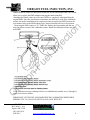
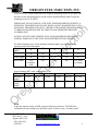
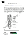
OREGON FUEL INJECTION, INC. 6.5L DS Pump Diagnostics LOW POWER 1. Low or no fuel supply pump pressure 2. Dirty fuel filter 3. Wastegate control solenoid ec tio n To properly diagnose a 6.5L vehicle with the DS model pump you will need a scan tool. The 1994 and 1995 are OBD1 and the 1996 through the 2000 model year is OBD2, so the diagnostic codes are different depending on the year range. nj WHITE SMOKE 1. Low or no fuel supply pump pressure 2. Retarded timing, use Tech 2 scan tool to perform TDC offset learn procedure. We normally set the timing to -1 to -1.5 degrees. Fu el I BLACK SMOKE 1. Dirty air filter 2. Waste gate control solenoid failure, or low vacuum. 3. Worn injectors (excess carbon on the nozzle tips) 4. Low or no fuel supply pump pressure 5. If this occurred after the plenum chamber (intake) was removed, check the EGR tower gasket, if not seated EGR gases enter the intake unrestricted and in excessive quantity. 6. Restricted exhaust system, if the vehicle has been “babied”, the cat will partially plug. Take the vehicle out for several full throttle accelerations to clear out the exhaust on HARD START HOT 1. If the complaint is a hard start after a hot soak, not a stalling condition then hard start, check for a minimum cranking speed hot of 200 rpm. O re g MISS 1. Worn injectors 2. If the engine was overheated, check for a head gasket problem, usually on the turbo side (usually #4 & #6). 3. See Misfire Codes further below. NO START, DIES INTERMITTENTLY OR STALLING This is often caused by a bad PMD (Pump Mounted Driver or Fuel Control Solenoid Driver); however it is unusual to have multiple failures of the PMD. A bad Fuel control Solenoid (part of the injection pump) can cause the same symptoms and codes. A bad EUGENE 4036 West 1st Ave. Eugene, OR 97402 (541) 485-1434 8/28/2015 www.oregonfuelinjection.com 1 OREGON FUEL INJECTION, INC. ec tio n EGR, EGR vent, wastegate control, and transmission solenoid are on the same quad driver circuit and can cause intermittent stalling. PMD (pump mounted driver) The pump mounted driver gets 12 volt power when the key is on from a fuse. The PCM then sends a signal to the PMD to close the fuel control solenoid. When the fuel control solenoid closes it sends a signal back to the PMD and that is relayed to the PCM. The response time of the closure signal is called C-time. C-Time should change slightly when the engine is accelerated or decelerated. A fixed CTime can indicate a bad Fuel Control Solenoid. If the C-Time is erratic when the RPM is stable then this usually indicates a bad PMD. See Wire Harness Testing for other possible problems. See PMD replacement guideline below. Fu el I nj PMD REPLACEMENT GUIDELINE Prior to replacement of the PMD we use the following guidelines to determine if a PMD may need to be replaced. This is a simple first step and is less in depth than the GM bulletin noted below. Also be aware that the PMD is powered by a quad driver circuit in the PCM. This circuit also powers the EGR vent solenoid, EGR control solenoid, wastegate control solenoid and the 1-2 shift solenoid. If any of these solenoids have an intermittent short the thermal protected quad driver circuit will trip and shut down all 4 circuits, which can cause intermittent stalling, then reset and run again. Check for system voltage between the pink and black (ground) wires at the wire harness connection to the PMD and Fuel Control solenoid (4 wires), it should be battery voltage. Fix low voltage issues as well as any other problems such as no fuel supply pump pressure before replacing the PMD. O re g on Replace the PMD if; 1. If complaint of intermittent dies with no codes and you can’t duplicate it, remember that a bad noise suppression harness can cause intermittent stalling. Intermittent dies with no closure errors (closure errors are usually caused by the fuel control solenoid). 2. Intermittent stalling and C-Time varies, as normal, during acceleration and deceleration (if C-Time is “stuck” at 1.95ms or 2.25ms this usually means a bad fuel control solenoid). 3. If you have a no start and C-Time is 1.95ms (94-95) or 0.01ms (96-2000) replace the PMD 4. C-Time is erratic at idle while idle rpm is stable. Note: Normal C-Time is between 1.5ms – 1.9ms. C-Time readings that are too high, but stable, are usually a result of a bad fuel control solenoid inside the injection pump not a PMD. EUGENE 4036 West 1st Ave. Eugene, OR 97402 (541) 485-1434 8/28/2015 www.oregonfuelinjection.com 2 OREGON FUEL INJECTION, INC. If the PMD is missing the heat transfer pad, it can overheat and cause intermittent stalling. If the PMD is not mounted to the a heat sink, either the pump housing ec tio n If the problem you are experiencing doesn’t correspond with the problems noted above then follow the trouble shooting below to help pinpoint a possible bad PMD. Fu el I nj GM Bulletin #77-63-06A – follow these instructions if PMD replacement guidelines do not apply. 1. Check fuel system for air (check at fuel return from pump), supply pump pressure, and fuel filter condition. 2. Check the PCM and injection pump wiring harness for chaffing and/or loose terminals at the PCM connector, the 15 pin connector and the PMD connector. See the WIRE HARNESS CONNECTIONS section for more information. 3. Check all engine and vehicle harness grounds. 4. Check for loss of ignition voltage on terminal "D" at the PMD connection to the injection pump. Refer to ENGINE CONTROLS IN THE 1998 SERVICE MANUAL FOR ALL MODEL YEARS. 5. Verify that the condition is still present: - If the condition is no longer present, the vehicle is repaired - If the condition is still present, and there are active DTC’s set, go to step 6. - If the condition is still present, and there are NO active DTC’s set, go to step7. 6. For active DTC’s 35 or P1216, refer to Engine Controls in the 1998 Service Manual for all model years. If the DTC diagnostic table flow chart directs you to replace the injection pump, replace the PMD (Pump Mounted Driver) which is also called the Fuel Solenoid Driver. Go to step 9. re g on 7. For stall condition, disconnect the Optical Sensor (Encoder Sensor) and operate the engine in back up mode (you will experience an extended crank time during starting, up to 15 seconds). A bad noise suppression harness or no noise suppression harness can also cause a stalling condition. If the condition is still present replace the PMD only. Go to step 9. O 8. For a no start condition, check injection pulse width (94-95) or C-Time (96-2000 Fuel Solenoid Closure Time) with a scan tool, while cranking (maintain minimum cranking speed 100 rpm cold and 200 rpm hot). If C-Time is 1.95ms (94-95) or 0.01ms (96-2000) replace the PMD. Go to step 9. 9. Replacing the PMD: The PMD must be mounted to a “heat sink” of some kind. Stanadyne (Injection Pump Manufacture) states that the PMD must be mounted to the injection pump with the heat pad underneath it. In order to mount the PMD to the injection pump you must remove the intake manifold. If you don’t want to remove the intake manifold, you could purchase a EUGENE 4036 West 1st Ave. Eugene, OR 97402 (541) 485-1434 8/28/2015 www.oregonfuelinjection.com 3 OREGON FUEL INJECTION, INC. re g on Fu el I nj ec tio n remote mount kit such as the BD remote mount kit, and an aftermarket PMD. This would allow you to replace the PMD without removing the intake manifold. Stanadyne has finally come out with a new PMD it is completely redesigned from the original PMD. Since the wire harness connections are different as well as the calibration resistor, the intake manifold must be removed in order to replace the PMD, because the wire harness between the PMD and the Fuel Control Solenoid will have to be replaced. Removing the PMD requires a T15 TORX bit. Replace the heat transfer pad and use snap ring pliers to remove the calibration resistor. Install the calibration resistor into the new PMD. O If the calibration resistor is damaged, there is an identification number on it (1 through 9) and we have them available. IMPORTANT: IF THE FUEL SOLENOID DRIVER CALIBRATING RESISTOR IS MISSING, DTC 56 (1994 1995) OR P1218 (1996-1998) WILL SET. EUGENE 4036 West 1st Ave. Eugene, OR 97402 (541) 485-1434 8/28/2015 www.oregonfuelinjection.com 4 OREGON FUEL INJECTION, INC. INSTALL FUEL SOLENOID DRIVER: Align the mounting screws on the PMD with the holes on the injection pump (or on the remote mount PMD heat sink) Torque the mounting screws to 23 LB-IN. ec tio n IMPORTANT: DO NOT INSTALL THE FUEL SOLENOID DRIVER WITHOUT A NEW HEAT TRANSFER PAD. DO NOT REUSE A HEAT TRANSFER PAD. USE A NEW HEAT TRANSFER PAD ONLY. THE HEAT TRANSFER PAD IS REQUIRED TO PREVENT RAPID FAILURE OF THE FUEL SOLENOID DRIVER FROM OVERHEATING. NOTICE: DO NOT OVER TIGHTEN FUEL SOLENOID DRIVER MOUNTING SCREWS. DAMAGE TO THE FUEL SOLENOID DRIVER WILL RESULT. x Crank signal 0 Yes, extended crank X = good signal, 0 = no signal Yes 0 x Yes No Yes, noisy on startup 200 853 Hz 700 2987 Hz 800 3413 Hz 13 Hz 47 Hz 53 Hz O re g on Hertz Readings (HZ) while cranking and at idle RPM 140 160 180 High Res. 597 Hz 683 Hz 768 Hz Signal Cam and 9 Hz 11 Hz 12 Hz Crank Signal 0 x Fu el I Will it start? x nj For Other Starting Issues, Check the high resolution signal, cam signal (from the injection pump) and crank signal. High Res. 0 x x x signal Cam signal 0 x x x EGR Light duty engines utilize an EGR system to help meet emissions. The EGR flow calculation on some models uses the MAF sensor. If there are any “air intake leaks” EUGENE 4036 West 1st Ave. Eugene, OR 97402 (541) 485-1434 8/28/2015 www.oregonfuelinjection.com 5 OREGON FUEL INJECTION, INC. ec tio n either MAF or EGR codes can set. A missing or improperly sealing EGR tower gasket can cause either or both codes to set. Low or no vacuum from the vacuum pump can also cause EGR codes to set. A missing EGR tower gasket can cause a MAF low code to set, along with excessive black smoke, because it is pulling exhaust gases instead of clean air through the air filter. Failure to remove the block off plates from the intake manifold gaskets for a light duty engine can cause EGR codes because there will be no exhaust gases getting to the EGR valve. Fu el I nj FUEL SUPPLY PUMP The supply pump operates during cranking and after the engine oil pressure comes up. The supply pump is driven from a relay on the firewall or in the under hood fuse/relay center. The oil pressure sensor also includes a switch to operate the supply pump once oil pressure comes up after starting. The supply pressure should be between 5-7 psi at idle. Test at the fuel filter drain at the front of the engine near the coolant crossover. Be aware that this is a test on the dirty side of the filter and if the filter is dirty the actual supply pressure to the injection pump will be lower. If the fuel supply pressure is zero, remove the fuel supply pump relay and jump #30 & #80 connector, this will send power to the supply pump with the ignition on. If you have good supply pressure now, then the most likely cause is a bad oil pressure sending switch. Low supply pressure can cause DTC P0370 (17) and P0251 (18) to set due to aeration in the fuel, after all it is an optical sensor and it can’t see through an aerated mix. O re g on MISFIRE CODES Misfire codes are handled differently for different years. Some misfire codes go by firing number order, in other words a misfire code for #2 would be #8 cylinder because it is the #2 cylinder in firing order. Check the service manual for the year you are working on. Firing order is EUGENE 4036 West 1st Ave. Eugene, OR 97402 (541) 485-1434 8/28/2015 www.oregonfuelinjection.com 6 Fu el I nj ec tio n OREGON FUEL INJECTION, INC. INJECTORS The injectors on the 6.5L are usually only good for about 100,000 miles. They get a lot of carbon blown up inside of the nozzle tip. This results in poor atomization and poor spray patterns. re g on ENCODER SENSOR If you have a no start condition, disconnect the encoder (optical) sensor and crank the engine for 15-20 seconds. If it starts then the problem is with the optical sensor. The encoder sensor has to be able to see through the fuel inside the pump, if there is any air in the fuel it can cause trouble codes to set. Dirty fuel, SVO, no fuel supply pressure (air in system) or dyed fuel can all cause a problem with the encoder sensor “reading” the windows in the cam disk. There are 8 windows in the low resolution circuit and 512 windows in the high resolution circuit. In on minute at idle the high resolution circuit needs to read about 180,000 windows, in order to not set a code. O TDC OFFSET LEARN The pump to engine timing must be set with a scan tool. You need to do the TDC offset learn procedure in order to set base pump to engine timing. TURBO EUGENE 4036 West 1st Ave. Eugene, OR 97402 (541) 485-1434 8/28/2015 www.oregonfuelinjection.com 7 OREGON FUEL INJECTION, INC. Fu el I nj ec tio n The turbo on the 6.5L EFI engine has a wastegate actuator that is controlled by vacuum. The wastegate actuator on the 94-2000 turbo does not have a spring, when no vacuum is applied the wastegate will “flop” back and forth. If the wastegate actuator holds a vacuum and it moves freely back and forth, when no vacuum is applied, then there is nothing wrong with the wastegate actuator. A turbo boost problem and DTC P0236 (78) is normally caused by low vacuum (need 20 inches HG) or a bad wastegate control solenoid. To inspect the turbo, remove the inlet hose from the compressor inlet and make sure the turbo spins freely and that the compressor wheel does not rub on the housing when pushed to the side. Some side play is normal, because the bearings “float” on oil when the oil pressure comes up after starting. The turbo pulls crankcase fumes through the CDR valve. It is normal for the turbo to discharge oil from the compressor housing. You have to determine if you have more oil coming out versus going into the compressor housing. A plugged air filter or bad CDR valve can cause excessive oil to be pulled out of the engine and discharged from the turbo back into the intake. If the silicone hose connecting the compressor discharge is not sealed with a minor amount of silicone sealant than the hose connection will weep oil past the hose. WASTEGATE CONTROL SOLENOID The wastegate (WG) control solenoid controls the amount of vacuum going to the wastegate actuator on the turbo. The WG solenoid is controlled via a pulse width modulated signal from the PCM. WIRE HARNESS TESTING Poor electrical connections or wiring can cause most intermittent problems. Perform a careful check of the suspected circuit for the following: re g on Inspect and ensure the integrity of all related wiring harness connectors. If the wiring harness connectors are not properly put together or engaged before they are locked together, numerous types of conditions may occur. This may include many intermittent symptoms and DTC codes. O The first step in any type of electrical diagnosis is that a visual and physical inspection be completed of the wiring harness connectors for integrity. Many times, the vehicle may be repaired just by disconnecting and reconnecting the connectors. As with all repairs to wiring harness connectors and terminals, a pin test of the terminals within the connector should be performed. A pin test is performed by inserting the proper size terminal test tool (not a paper clip), into the terminal to determine whether or not the terminal is making good contact, or whether it has been damaged from prior improper connection, multiple connections or lack of connection. COMMON CODES EUGENE 4036 West 1st Ave. Eugene, OR 97402 (541) 485-1434 8/28/2015 www.oregonfuelinjection.com 8 OREGON FUEL INJECTION, INC. Note; multiple codes can set for just one fault, as if the other codes wanted to come to the party. On an OBD2 system use the Tech 2 scan tool to determine which code set first and under what condition, A DTC P0370 (17) can trip a DTC P0251 (18), a DTC P0251 can trip a P0335 (19) and a DTC P0335 can trip a DTC P1216 (35) or DTC P1217 (36) ec tio n DTC P0216 (34) injection pump timing control circuit 1. Watch the stepper motor and make sure it retracts when activating TDC learn with a scan tool. If the stepper is not operating properly this code will set. 2. This code will set if injection pump timing has not been set correctly. 3. It will also set sometimes if the crank sensor is faulty. 4. If the stepper motor shaft was bumped hard during handling while the pump was off, that can cause the stepper motor to bind and quit working. Fu el I nj DTC P0236 (78) turbo boost performance 1. This code is usually caused by a bad wastegate control solenoid or low system vacuum. 2. Check vacuum at the wastegate actuator connection on the turbo. It should be 15” at idle. If it is not and vacuum at the inlet to the wastegate solenoid is at least 24”, then the solenoid is bad. If the vacuum pump is not producing 24” of vacuum, then there are either leaks or the pump itself is bad. DTC P0251 (18) injection pump cam sensor circuit (optical sensor) 1. Similar to P0370 (see comments under DTC P0370), sets when cam reference counts are missed. Can also be set by contaminated fuel or aerated fuel like P0370. 2. Bad connections in the harness connectors and or a bad noise suppression harness are common causes for this code. on DTC P0335 (19) crankshaft position reference error 1. Bad crank sensor or wiring issue. O re g DTCP0370 (17) timing reference high resolution system performance(optical sensor) The optical sensor (encoder, cam) is used by the injection pump to determine injection timing relative to engine position. This code and the P0251 set when counts are missed from the pump cam but picked up from the engine crank position sensor. The optical sensor can not be changed with the pump on the engine. The pump has to be partially disassembled parts replaced and then tested on the test stand. 1. Can be caused by aeration in the fuel from a plugged fuel filter, low fuel supply pump pressure, or low fuel level in fuel tank. 2. Contaminated fuel or fuel with dyes in it. Red off road fuel or automatic transmission fluid in fuel can also cause the optical sensor to miss counts. EUGENE 4036 West 1st Ave. Eugene, OR 97402 (541) 485-1434 8/28/2015 www.oregonfuelinjection.com 9 OREGON FUEL INJECTION, INC. 3. Bad connections in the harness connectors and/or a bad noise suppression harness are common causes for this code. ec tio n DTC P1216 (35) fuel solenoid response time too short 1. Sets if closure time is less than 1.2 ms or less than .75ms on later years. 2. Commonly caused by bad PMD. Check the PMD harness circuits for good voltage and grounds prior to replacing the PMD. See “PMD Replacement” above. 3. On some occasions this code can be set by a bad fuel solenoid in the injection pump. nj DTC P1217 (36) fuel solenoid response time too long 1. Closure time more that 2.5 ms. 2. Can be caused by a weak fuel control solenoid, bad PMD, poor grounds, low supply voltage at PMD. See “PMD Replacement” above. Fu el I DTC P1218 (56) Injection pump calibration resistor error 1. Usually is caused by a missing calibration resistor, and this code sometimes will only set after attempting TDC offset learn. DTC P1125 (84) Accelerator Pedal Position Sensor System Performance 1. This code can set if your foot is on the throttle and brake when key is turned on. O re g on DTC P1214 (88) injection pump timing offset error 1. The pump to engine timing must be set within +2.02 to -2.02 degrees when doing TDC offset learn or this code will set. You must reset timing (rotate the pump), clear the code and retry TDC offset learn. 2. This code could also set if the starter was used to crank the engine over while installing the injection pump, this will sometimes partially shear the crankshaft timing chain gear key. EUGENE 4036 West 1st Ave. Eugene, OR 97402 (541) 485-1434 8/28/2015 10 www.oregonfuelinjection.com