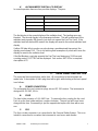
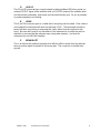
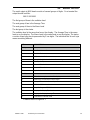
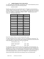
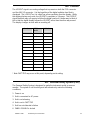
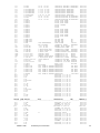
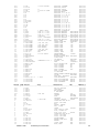
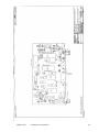
1
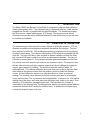
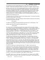
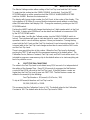
OPERATIONS AND REPAIR MANUAL
MODEL 2080
PULSE NEUTRON SURVEY METER
September 1999
Revision B
health physics instruments
330 D South Kellogg Ave, Goleta, CA 93117 Tel 1-805-967-8422
TABLE OF CONTENTS
I.
II.
III.
IV.
V.
VI.
VII.
VIII.
IX.
X.
XI.
XII.
XIII.
XIV.
XV.
XVI.
XVII.
INTRODUCTION.......................................................................................................................2
PRINCIPAL OF OPERATION...................................................................................................2
NORMAL OPERATION ............................................................................................................3
SWITCH/INDICATOR DESCRIPTIONS..................................................................................5
A. TEST 32
5
B. TEST 0
5
C. RESET
5
D. LAMPS
5
E. PANEL DISABLE
5
F. POWER ON
5
G. DISPLAY
5
H. SET
6
I.
PANEL INDICATORS
6
J.
HORN
6
K. ALPHANUMERIC DIGITAL LCD DISPLAY
7
REAR PANEL DESCRIPTION..................................................................................................7
A. POWER CONNECTION
7
B. FUSE
7
C. PSS
7
D. AUX I/O
8
E. HEAD
8
F. BEAM GATE
8
RADIATION CALIBRATION ...................................................................................................9
A. CALIBRATE MODE:
9
B. STORING THE CONSTANTS
10
C. SAMPLE CALIBRATION
11
1. Gamma Calibration
11
2. Neutron Calibration
11
MASTER SETTINGS...............................................................................................................12
A. FAST TRIP CALCULATIONS
12
MAINTENANCE FUNCTION.................................................................................................13
INTERNAL ADJUSTMENTS, AND CONTROLS .................................................................15
SERVICE ..................................................................................................................................16
CIRCUIT DESCRIPTION ........................................................................................................17
A. HEAD
17
B. READ-OUT
17
SERIAL OUTPUT ....................................................................................................................19
A. UNDERSTANDING THE STATUS BYTES
20
LOGOUT ..................................................................................................................................21
PERSONAL SAFETY SYSTEM (PSS) ...................................................................................21
REAR PANEL CONNECTORS/CABLES ...............................................................................22
A. I/O CONNECTOR PINOUT
22
B. HEAD CONNECTOR
22
C. PSS CONNECTOR
23
PART LIST ...............................................................................................................................24
SCHEMATICS..........................................................................................................................28
MODEL 2080
Health Physics Instruments
1
I.
INTRODUCTION
The Model 2080 Pulse Neutron Survey Meter is designed to measure either pulsed or
steady state neutron fields. The instrument may be operated either as a fixed monitor
plugged into the wall, or portable with the internal batteries. The instrument displays
the dose rate on a digital alphanumeric LCD display. The microprocessor based
instrument incorporates many additional features to make it both easy to use and easy
to maintain and calibrate.
II.
PRINCIPAL OF OPERATION
The instrument uses the principal of nuclear capture to detect the neutrons. A 25 cm
diameter polyethylene pseudosphere moderator thermalizes the neutrons. They are
then captured by silver foil. The resulting beta activity is proportional to the previously
acquired neutron dose. The betas are detected by a GM tube that is wrapped with the
silver foil. Since the GM tube is also sensitive to external radiation not from the silver
foil, a second GM tube is used to cancel out any background radiation. The second
GM tube is covered with tin. This presents the same gamma attenuation as the silver.
The counts from each detector are scaled in two separate scalers. The response from
the two detectors may not be the same to gamma rays due to differences in detector
volume, gas pressure or shielding. The two tubes must be matched within 1%
mathematically. The software multiplies the counts from each scaler to balance them,
then subtracts the gamma counts from the neutron counts to obtain Net Neutron
counts. It then divides this number by a calibration factor to obtain a corrected
reading. The resulting values because of the low counting rate need to be averaged
over a period of time. This is performed by the digital filter. In essence it is a 16 register
rotating stack that stores each new value over the oldest one, adds up the stack, then
divides by 16 to obtain an averaged signal level. The time taken for a sample is
determined by the average time. The alphanumeric display can display several different
parameters and functions besides the radiation level. In addition the microprocessor
controls the outputs, lamps, and horn.
MODEL 2080
Health Physics Instruments
2
III.
NORMAL OPERATION
The instrument may be operated either from 110 VAC, 60 HZ or from the internal
batteries. When first received the batteries may need to be charged. Plug one end of
the line cord into the back of the instrument and the other end into an electrical outlet.
The LED on the front panel marked AC POWER should light. This indicates that the
instrument is plugged into the wall. The batteries take about 30 hours to fully charge.
The instrument may be operated on either power source without reservation. If the
batteries are too low for proper operation, the instrument will not turn on. If the
instrument does turn on and the batteries are low, the display will flash LOW BATT to
indicate that the batteries are low.
The whole read-out box tilts up or down for best viewing angle. It is secured in position
by the two thumbscrews on the sides.
Turn the instrument on. The horn will beep to indicate that the instrument is functioning
properly and the display will show;
XXX mrem/h
The XXX is the radiation level and will indicate the level from 1 to 400 mrem/h. If the
radiation was above 400 mrem/h the display will show;
>400 mrem/h.
The value shown on the display represents the average of 16 consecutive readings.
This is done to smooth out the fluctuations in the display. The time between readings is
determined by the Average Time. The Average Time can be seen by pushing the
DISPLAY AVERAGE TIME button. The display will now show X x 15 seconds ; the X
representing either 1,2,4,8,16 or 32. There are two ways of thinking of this number.
One way is that the total time for a new reading is X x 15 seconds, just like the display
says. This means that if the Average Time is set to 8 the time for a complete new
reading would be 8 times 15 seconds or 120 seconds or 2 minutes.
The other way of thinking has to do with update time. The update time is the time
between readings and is the Average Time times 15/16 seconds. When the Average
Time is 1 the display will update every 15/16 seconds. When it is on 8 it will update
every 8 time 15/16 second or 7.5 seconds. No matter where the Average Time is set it
still takes 16 updates to replace the running average for the display but the display will
change every Average Time times 15/16 second. If the PANEL DISABLE switch is not in
the locked position, then the Average Time may be changed by pushing the SET switch
either up or down.
The DISPLAY switch also shows the Alarm Level. The Alarm Level may be set
anywhere from 0 to 400 mrem/h. When the Alarm Level is matched or exceeded the
horn turns on. If the instrument is plugged into the wall or the lamps are turned on for
battery operation, then the three colored lamps will flash. This alarm is self resetting
and will not latch. When the level falls below the Alarm Level the alarms will turn off.
The RESET switch on the front panel resets the instrument to zero. It may be pushed at
any time. It is locked out of operation by the PANEL DISABLE switch.
The LAMPS switch turns on the lamps if the instrument is on batteries and the PANEL
DISABLE switch is not locked. Push it once to turn on the lamps. Push it again to turn
MODEL 2080
Health Physics Instruments
3
them off. The battery life is greatly reduced with the lamps on and for this reason they
cannot be left on if the PANEL DISABLE switch is locked. If the AC power is removed
and the instrument is turned on, the lamps will be turned off.
In addition to the standard Alarm Level which is based on the radiation level displayed,
there is another internal alarm level which is based on the rate of radiation received
every 15/16 seconds. If this internal level that is set to about 500 mrem/h is exceeded,
then the instrument will show FAST TRIP in the display. This is a latching alarm and
once tripped can only be turned off by either turning the instrument off then back on or
by pushing RESET. The instrument will then resume normal operation.
The instrument checks the status of the detectors and if it detects that one is not
working properly, it shows FAIL on the display. FAIL is self-resetting.
Figure 1 Front and Rear Panels
MODEL 2080
Health Physics Instruments
4
IV.
SWITCH/INDICATOR DESCRIPTIONS
The front panel switches control the operation of the instrument. There are no rear
panel switches. They are described in order; the top row from left to right, then the
bottom row from left to right.
A.
TEST 32
Simulates 32 mrem/h at the GM tubes. The display will increment to 32 mrem/h after
the Average Time. This test does not interfere with the routine to check for detector
failure. Holding in TEST 32 will not lead to a FAIL indication.
B.
TEST 0
Simulates no counts from the GM tubes. FAIL will occur in the number of update
cycles programmed in to FAIL COUNT (e.g., after 60 seconds). See SECTION VII
MASTER SETTINGS.
C.
RESET
Resets the stack, and resets the Average Time. If the Average Time was set to 32, and
the RESET was pushed, the time for the next update would be 32 15/16th seconds or
30 seconds. Will not work if the PANEL DISABLE is locked.
D.
LAMPS
Turns on or off the front panel indicator lamps if the instrument is on batteries and the
PANEL DISABLE is unlocked.
E.
PANEL DISABLE
The PANEL DISABLE switch needs a key to operate. When it is in the locked position,
the RESET, LAMPS and SET UP and DOWN switches will not function. When it is in the
Unlocked position, all front panel switches function.
F.
POWER ON
This turns on the power to the instrument.
G.
DISPLAY
This switch changes the display from mrem/h to the Alarm Level or to the Average Time
setting. The radiation level is the normal display. Pushing the DISPLAY ALARM will
change the display to read
XXX mrem/h Alarm
The XXX is the Alarm Level setting. After the switch is pushed, the display will remain
for about 5 seconds after which it will revert back to the radiation level. The alarm level
may be set at any positive integer from 1 to 400 mrem/h.
Pushing the DISPLAY AVERAGE TIME will cause the display to read:
XX x 15 seconds
The XX is the Average Time and it will only read 1,2,4,8,16 or 32. After the switch is
pushed, the display will remain for about 5 seconds after which it will revert back to the
radiation level.
MODEL 2080
Health Physics Instruments
5
H.
SET
The SET switch is used in conjunction with the DISPLAY switch. The SET UP or SET
DOWN are used to set the Alarm Level and the Average Time. It has no function when
the instrument is reading the radiation level.
When the display shows the Average Time (The DISPLAY AVERAGE TIME switch was
pushed) the SET UP or SET DOWN switch will cause the displayed Average Time to
increase or decrease, but only if the PANEL DISABLE is unlocked. It is necessary to
hold the switch down until the desired reading is obtained. The display will not roll over
at either end. The display will remain on for 5 seconds after the last switch was
pushed.
When the display shows the Alarm Level (The DISPLAY ALARM switch was pushed) the
SET UP or SET DOWN switch will cause the displayed Alarm Level to increase of
decrease, but only if the PANEL DISABLE switch is unlocked. If either SET switch is
held down for 7 seconds, the display, instead of increasing (or decreasing) by units,
will increase (or decrease) by 10s. This setting does not roll over at either end.
The Alarm Level and the Average Time are remembered even when the power is turned
off and the batteries are removed. The instrument stores these values when the display
reverts back to the normal radiation level. Consequently if you change either one then
turn the power off before going back to a normal display, the instrument will not store
the new value.
I.
PANEL INDICATORS
AC POWER indicator indicates that the instrument is plugged into the line and that the
batteries are charging.
GREEN, YELLOW, and RED Bar Lights indicate the radiation level. In normal operation,
one of these lights flashes according to the following:
GREEN
0 to 2 mrem/h
YELLOW
3 to 19 mrem/h
RED
above 20 mrem/h
All three flash when the Alarm Level is exceeded. The LAMPS switch will turn these
indicators on and off if the instrument is on batteries and the PANEL DISABLE is
unlocked. When the instrument is on and operating from AC power, the lamps will
function normally and cannot be turned off using the LAMPS switch. The lamps are off
when the instrument is switched to battery operation.
J.
HORN
The horn is used to indicate the status of the counts from the neutron GM tube, the
Alarm and various beeps from the program. The horn volume control changes only the
loudness of the beep from the neutron GM tube. Turn it up and the horn will beep
every time a count is detected from the neutron GM tube.
When the instrument is first turned on the horn will beep if all is OK. This is a loud
beep. If the volume control is turned up then a soft beep will also be heard as soon as
the instrument is turned on followed by the All OK beep. When the Alarm Level is
exceeded the horn will also turn on continuously at full volume and is not affected by
the setting of the volume control.
MODEL 2080
Health Physics Instruments
6
K.
ALPHANUMERIC DIGITAL LCD DISPLAY
In normal operation there are four possible displays. They are:
DISPLAY
COMMENT
xxx mrem/h
Radiation level
>400 mrem/h
Over range indicator
FAIL
GM tube failure
FAST TRIP
Fast Trip Level exceeded
The first display is the normal display of the radiation level. The leading zeros are
blanked. The second display is the overrange indicator. This will be displayed if the
radiation level exceeds 400 mrem/h, but does not exceed the Fast Trip Level. If the
radiation level falls below 400 mrem/h the display will revert to the normal radiation level
display.
If either GM tube fails to produce a pulse during a predetermined time period, the
display panel shows FAIL. This is not latching and resumption of pulses will cause the
display to revert to the radiation level.
If the Net Neutron count rate exceeds the Fast Trip Level during any 15/16 second
counting period, FAST TRIP will be displayed. See section XIV PSS for a complete
description of PS
V.
REAR PANEL DESCRIPTION
The rear panel has several plugs and a fuse. All connections to the instrument are
made here. A description of each plug from left to right, while looking at the back panel
is as follows.
A.
POWER CONNECTION
The rectangular line cord connector plugs into an IEC 320 cordset. The instrument is
designed for 110 VAC, 60 Hz.
B.
FUSE
The fuse holder contains a 1/4 A 3AG Fuse. To remove the fuse, unplug the line cord.
Push in on the fuse holder and turn counter-clockwise. The end cap will come loose
along with the fuse. Reassembly is just the opposite but replace the fuse with a new
one.
C.
PSS
The 6 pin circular connector is a connection for the Personal Safety System. This in an
interlock connection for use when the instrument is used as an area monitor.
MODEL 2080
Health Physics Instruments
7
D.
AUX I/O
This 25 pin DB connector has several outputs including buffered GM tube counts, an
analog LOGOUT signal of the radiation level, an RS-232A output of the radiation level
and instrument parameters, and power and reserved function pins. Its use is primarily
in system expansion and testing.
E.
HEAD
This 9 pin DB connector goes to a cable that in turn plugs into the head. If this cable is
not installed the instrument will work but will show a FAIL. The instrument should be
turned off when connecting or removing this cable, either from the read-out or the
head. No harm will come to any electronics if the instrument is on while the cable is
attached or removed but the program may not operate properly. Just turn the
instrument on and off if this happens.
F.
BEAM GATE
This is an electrically isolated connector that will turn off the counts from the detector
when a positive signal is applied to the beam gate. The connector is isolated from
ground.
MODEL 2080
Health Physics Instruments
8
VI.
RADIATION CALIBRATION
The instrument has a special routine for radiation calibration that facilitates balancing
the two tubes as well as setting the absolute radiation level. The instrument does not
have to be opened to calibrate it and the calibration is done using the front panel
controls. The calibration is completely digital.
A.
CALIBRATE MODE:
To enter the calibrate mode make sure the instrument is unlocked. Hold down the
RESET Switch and the LAMPS switch. Now turn the instrument on. The word CAL will
appear to tell you that you are in the calibrate mode.
The display will then show three numbers. This is the balance section of the calibrate
routine. The idea is to balance the counts from the two GM tubes.
Starting from the left the first number is the counts from the neutron GM tube divided by
256. If the left hand display reads 26 then it means that the internal counter for the
neutron GM tube has accumulated 256 times 26 or 6656 counts. The next number is
the balance. It is either positive or negative. If there are too many gamma counts then
the number goes negative, if there are too many neutron counts then the number goes
positive.
The next and last number is the Balance Constant. This number is raised and lowered
by the SET UP/DOWN switch on the front panel. Push the SET UP/DOWN switch up
and hold it there and every second the number will increase by one. Hold it down and
the number will go down by 1 every second. This is the way the Balance Constant is
changed.
Internally the instrument has a counter for each GM tube. Each counter has a capacity
of 16777215 counts. In a gamma field the GM tubes count about 7 cps per mR/h.
Thus in a 10 mR/h field 10 minutes of counting will add about 42000 counts (10 min x
60 sec/min x 7 cps/ mR/h x 10 mR/h). Since this is divided by 256 before it is displayed
the display will show about 164 (42000/256). The total number of counts that can be
displayed is 61695. At this time the program will accept no more counts. This
represents about 62 hours of counting at 10 mR/h. Enough to go have a long coffee
break after starting the instrument. Incidentally the RESET button will reset the numbers
back to zero. Push it any time you like. It will not however change the Balance
Constant.
Every second the counts from the gamma counter (divided by 256) are multiplied by
the Balance Constant and subtracted from the counts from the neutron counter
(divided by 256) multiplied by 100. The result, positive or negative goes into the center
number in the display. Positive means that the Balance Constant is too low. Negative
means that the Balance Constant is too high. Mathematically this is expressed by:
balance=100(n cts/256) - (Balance Constant)(g cts/256)
In practice the instrument will be put into a gamma field for either a known period of
time, or until a certain number appears on the counter. The more counts the better but
too many may confuse the issue. The Balance Constant can only be set in unit
increments (or about 1% adjustment) When 1000 neutron counts are displayed, the
balance will read within + or - 1000 if the Balance Constant is within 1%. With 1000
MODEL 2080
Health Physics Instruments
9
counts in the display the instrument is easy to balance and the statistical errors of + or
- 1 count are insignificant.
Then the SET UP/DOWN switch is manipulated until the balance number is as close to
zero as possible. It will probably never be right on zero but as close to it is the goal. A
slightly positive number will make the instrument read more neutrons in a high gamma
field. The SET UP/DOWN switch is always working and can be moved at any time to
change the Balance Constant and thus to change the balance. The display is updated
every second.
Once a significant number of counts have been accumulated and the Balance
Constant adjusted satisfactorily, the counters may be zeroed using the RESET. A
subsequent count may be used to demonstrate reliability and reproducibility, but
otherwise unnecessary. That is all there is to balancing the instrument.
The next phase is to set the absolute Calibration Factor.
To do it, push the LAMPS button. The display will look like the normal display except in
place of the words "mrem/h" on the right hand side of the display, will be the 3 digit
Calibration Factor, followed by the letter C. The letter C is to remind you that you are in
the calibration mode. The Calibration Factor may now be set with the SET UP/DOWN
switch.
All Switches will work like normal on the front panel except for the PANEL DISABLE
switch (More about it in a minute). The Average Time can be changed. The RESET
button works like normal.
There are several functions that are defeated. The Alarm horn will not work. The
overrange indicators will not work. The FAST TRIP will be displayed but it is not
latching. These were defeated to allow testing of the FAST TRIP and to keep the ears
of the calibration personnel from ringing after calibration.
The radiation level reading is inversely proportional to the Calibration Factor, i.e.,
raising the Calibration Factor will lower the mrem/h reading. Once the neutron radiation
level has come to equilibrium, it is easy to determine the approximate Calibration
Factor by multiplying the current Calibration Factor by the ratio of the current radiation
level indication to the "true" radiation level. Although the display updates once per
second, the radiation level needs one averaging time to completely fill the register stack
with new data. After getting close to the correct value it is a good idea to make small
changes, wait one averaging time then make another small change until the instrument
reads properly.
B.
STORING THE CONSTANTS
Up to this point the Balance Constant and the Calibration Factor have been changed
but they are only in volatile memory. If you turn the power off now the new balance and
calibration numbers revert back to the old numbers. To make them permanent you
only need to turn the PANEL DISABLE back to lock and wait for the beep. The
instrument will resume operation just like it was turned on, and beep again to indicate
all is well. To change the calibration data again, it is necessary to enter the calibration
mode again.
The data can be saved at any time in the course of calibration. The instrument can be
balanced one day, then calibrated the next. It is easy to review the settings of the
MODEL 2080
Health Physics Instruments
10
Balance and Calibration by just entering the calibration mode, looking at the values,
then turning the instrument off. Unless the key is turned the values will not be changed.
If the key is turned and the values were not changed, the old values will be re-saved in
memory, and will therefore not be changed.
C.
SAMPLE CALIBRATION
The Model 2080 needs both a gamma calibration and a neutron calibration. The
gamma calibration is before the neutron calibration. Set the time constant to 8 x 15 or
higher for a more accurate calibration.
1.
Gamma Calibration
1. Turn the instrument off. Key should be in PANEL DISABLE position.
2. Hold down the RESET and LAMPS switch and turn the instrument on.
3. Set the instrument in a 20 mR/h gamma field and let the instrument count until the
counts in the 1st number are greater than 300. Center the source on the sphere. It
should be at least 1 meter away from the sphere.
4. Using the UP/DOWN switch to raise or lower the BALANCE CONSTANT (3rd
number) until the BALANCED NUMBER (middle number) is as close to 0 as
possible. Positive numbers are better than negative numbers.
5. Turn Key to LOCK to save the values, then return key to original position.
2.
Neutron Calibration
1. Turn the instrument off. Key should be in PANEL DISABLE position
2. Hold down the RESET and LAMPS switch and turn the instrument on.
3. Wait for display to stop changing and push LAMPS. The normal display will appear
with the letter C to indicate calibration.
4. Set the instrument in a 100 mREM/h neutron field. Wait 5 minutes for the silver foil to
reach equilibrium.
5. Using the UP/DOWN switch to raise or lower the CALIBRATION FACTOR until the
instrument reading is 100 mREM/h. Raising the CALIBRATION FACTOR will lower
the reading.
6. Check it at 50 mREM/h and wait 5 minutes for the silver foil to reach equilibrium.
Change the CALIBRATION FACTOR if necessary then recheck at 20 mrem/h.
7. Turn key to LOCK to save the settings and then turn instrument off.
8. If the CALIBRATION FACTOR was changed very much, repeat the gamma and
neutron calibrations.
MODEL 2080
Health Physics Instruments
11
VII.
MASTER SETTINGS
The Master Settings routine allows setting of the Fast Trip Level and the Fail Counter.
To enter into this routine turn the PANEL DISABLE to unlocked. Push the SET
UP/DOWN switch up at the same time hold the DISPLAY ALARM/AVERAGE TIME
switch to ALARM. Now turn the instrument on.
The display will show a single number, the Fail Count, in the center of the display. This
is the number of 15/16ths of a second that the instrument needs without a count from
either GM tube before it will display FAIL. Change the number by pushing on the SET
UP/DOWN switch.
Pushing the LAMPS switch will change the display to a 5 digit number which is the Fast
Trip Level. It starts out at 25000 and can be raised and lowered in increments of 256
by the SET UP/DOWN switch.
To save the data, Just like the Calibrate routine, turn the PANEL DISABLE switch to
locked. The instrument will beep to indicate that all is saved, then it will resume normal
operation in which case it will beep again as if it was just turned on. Turning the key
saves both the Fail Count and the Fast Trip Level and it can be turned at any time. If it
is turned while in the Fast Trip Level change section then it saves both the Fail Counts
and the Fast Trip Level.
There is one special function in this routine. When the Fast Trip Level is displayed,
pushing the TEST 32 will reset ALL the permanent memory to its default values. The
Calibration Factor, Balance Constant, Fast Trip Level, and Fail Count will be reset. It is
included to program a new memory chip to the default values or to start everything out
fresh if a problem occurs.
A.
FAST TRIP CALCULATIONS
The value in the Fast Trip Level is calculated every 15/16 seconds. It is independent of
the setting of the Average Time. Every 15/16 seconds it compares the Net Neutron
counts for that 15/16 seconds to the Fast Trip Level. If the Net Neutron counts are
higher than the Fast Trip Level it goes into FAST TRIP. The Net Neutron counts are
related to the mrem/h by the following:
Fast Trip Number = 50 (mrem/h) (Cal Factor / 100)
To trip at 500 mrem/h therefore set Fast Trip Level to:
50 (500) (100/100) = 25000
This assumes that the Calibration Factor is 100. The default value for the Calibration
Constant is 100. The default value for the Fast Trip Level is 25000.
MODEL 2080
Health Physics Instruments
12
VIII. MAINTENANCE FUNCTION
The maintenance function is built into the instrument to facilitate checking out the
instrument. Like the other secondary functions, this is entered by turning the instrument
on while a switch is depressed. In this case the switch is the TEST 32 switch. To get
into the maintenance function turn the PANEL DISABLE to unlock and hold down the
TEST 32 switch. Turn the instrument on. Immediately you will see the display with
many numbers and letters. If the instrument displays FAIL then the EEPROM is either
defective, not installed, or unprogrammed. See EEPROM section for more details. If
the instrument is plugged into AC power the display should look like:
1 2.0 LH 7N 7G
The first digit starting from the left is the switch number that was just pressed, in this
case the TEST 32. The next group of figures, the 2.0 is the voltage that should be at the
LOGOUT (-2.0 Volts). The third group, LH is an indication of both the AC Power
detector, and the Low battery detector. The two last groups, 7N and 7G are the counts
from each GM tube.
Most switches do double duty. The action of the switches in order is included in the
table below.
NAME
NUMBER
LOGOUT
ACTION
TEST32
1
-2.00
None
TEST 0
2
RMP
Ramps LOGOUT voltage from +1.2 to -5.0 Volts
RESET
3
+1.2
Resets lights, horn, and PSS
LAMPS
4
-3.2
Sets PSS
PANEL
5
----
Turns on Horn RESET to turn off DISABLE
SET UP
6
----
Turns on Green Light
SET DN
7
----
Turns on Yellow Light
ALARM
8
----
Turns on Red Light
AV TIME
9
----
None
You will notice that the switches follow a sequence around the panel starting at the
upper left hand corner and proceeding across the top row and then across the lower
row.
The LOGOUT Voltage also follows a pattern. RESET sets it for 0 mrem/h or +1.2 Volts.
TEST 32 sets it as for 32 mrem/h or -2.0V.
Lamps takes it to -3.2 Volts. These are used in adjusting the offset and gain trimmers
inside the instrument. The RMP stands for RAMPING. The voltage slowly ramps
between +1.2 and -5 Volts. At -5 Volts it starts over again at +1.2 Volts.
The Lamps and Horn are actuated by the switches shown in the table above. This is to
test them. They are turned off by RESET.
MODEL 2080
Health Physics Instruments
13
The PSS Relay is actuated by the LAMPS switch. Push it and the circuit is closed. After
about 5 seconds the contacts will open. This checks the watchdog timer that checks
for Microprocessor failure. If the LAMPS switch is pushed then the RESET switch the
relay should fall out immediately. This is the normal course of actuation by the
computer when it senses that PSS is not allowed.
The two H or L indicators show the status of the AC Power and the Low Battery
detector. The table shows their indicators;
AC Power L is AC Connected, H AC not connected
LOW BATT L is low Battery, H is good battery
On battery power they normally read HH on AC Power they would normally read LH.
The Last groups are the GM counters. The two letters next to the digits correspond to
N for neutron and G for gamma. The counters count down from 7 to 0 then return to 7.
They give an indication of the GM tubes counting. They start at 7 when the
maintenance mode is entered.
The maintenance mode also exercises the RS-232. It puts out "HI" continuously at 9600
baud.
MODEL 2080
Health Physics Instruments
14
IX.
INTERNAL ADJUSTMENTS, and CONTROLS
There are only 5 internal adjustments and they are all located on the circuit board in the
read-out box; 4 of the 5 are screwdriver adjustments. The 5th is the display contrast. It
can be rotated by the finger and is in the right hand corner of the circuit board if the
display is facing away from you. To gain access to the adjustments and the inside of
the case, remove the two screws located on the sides at the top back of the instrument.
The whole front panel and top, which are one piece, rotate up and forward, pivoting on
the lower front. There is a small reset push-button on the left hand side of the circuit
board. This resets the microprocessor whenever it is pushed (i.e., a warm boot). If it is
pushed it does the same thing as when the power is removed then re-applied. Don't
hesitate to push it.
Figure 2 Internal Controls
On the right rear of the circuit board there is also a set of pins with a jumper pushed on
one of them. This is the only internal adjustment to the microprocessor. It makes the
instrument go into the maintenance mode immediately at turn on. No switches need be
pushed to do it and its purpose is for testing when all else fails. To try it, put the jumper
on the two rear terminals and turn the instrument on; it should be in maintenance
mode. When the jumper is removed the instrument is in its normal mode operation.
The jumper can be removed from the instrument or it can be stored by pushing it over
only one pin.
The four screwdriver adjustments are factory set, however they may be changed or
checked depending on the use of the instrument. The two adjustments next to the
contrast control set the voltage gain and offset for the LOGOUT signal on the PSS
connector and the AUX I/O connector. To set them put the instrument into the
maintenance mode and monitor the LOGOUT voltage. Push RESET on the front panel.
Adjust the offset so the LOGOUT reads +1.2 Volts. Depress LAMPS on the front panel
MODEL 2080
Health Physics Instruments
15
and adjust the gain so the LOGOUT reads -3.2. It will be necessary to repeat the
sequence of the two adjustments because they interact somewhat.
To check the intermediate voltage values, see the MAINTENANCE FUNCTION for a
complete description of the LOGOUT test voltages.
The other two adjustments are the low battery and power fail detector. The low battery
adjustment is made by replacing the batteries with a power supply, and operating the
instrument without the line cord. Enter the maintenance mode. Turn the voltage that
replaces the batteries to 7.2 Volts. Adjust the low battery adjustment until the low
battery indicator in the display changes from L to H or H to L. This is an abrupt change
without hysteresis. About 1/4 turn will change the display. CCW turns the display to H
and CW turns it to L.
The Power Fail adjustment adjusts the voltage at which the instrument automatically
turns off even if the on-off switch is on. This keeps the instrument from reverse biasing
the batteries resulting in their catastrophic failure. Use the same connection as for the
low battery check except change the external power supply to 6.5 volts. Now turn the
Power Fail trimmer until the instrument just turns on. CCW will turn it on and CW will
turn it off.
X.
SERVICE
Servicing the instrument should be relatively easy since the instrument is designed in a
plug together modular fashion. The head and read-out are two separate items and the
plug in detector tubes are a third.
To gain access to the instrument the read-out box may be removed from the handle
and sphere by removing the thumbscrews. Two washers between the read-out and the
handle will fall out. Keep them and put them back when reassembling the instrument.
They keep the handles from scratching the case.
The detector box has 4 screws, two on each side. The cover lifts off. Inside is the high
voltage power supply and discriminators as well as the detector paddle. The detector
paddle unplugs from the board and the paddle removes by just pulling it upward.
The circuit board is held in the instrument by two screws through the board, and the
two screws holding the connector to the rear of the case. The stainless tube will have
to be removed before the board can be slipped out, it just pulls out.
The read-out box can be opened by removing two top rear screws on each side. The
whole top and front panel now pivot up on the two screws on the front bottom of each
side. The circuit board is held in place by the two screws on each side cutout on the
rear panel. When they are unscrewed and the connectors are removed from the circuit
board, the whole board slides out. Underneath the board are the batteries and the
power supply. The batteries just slip into the holders.
The front panel may be detached from the read-out box by removing the two screws on
the lower front of each side.
MODEL 2080
Health Physics Instruments
16
XI.
CIRCUIT DESCRIPTION
The instrument is divided into two distinct circuits the Head and the Read-out.
A.
HEAD
The signal starts at the detector tubes which put out a negative pulse that is
discriminated by U1. The negative going signal is then fed to a one shot that has a
pulse width of around 30 usec. Q1 and Q2 are power transistors that drive the line
between the head and the read-out. At the read-out end, the line goes through the LED
in an optocoupler and is returned to the head. This cancels the common mode signals
since the instrument was designed to operate with long lines between the head and
read-out. If they were to be longer than 100 feet the one shot should be made longer
by changing R20/21.
The Low voltage unregulated power is regulated by U4 to 5 volts. The high voltage of
+550 volts for the GM tubes is derived from a switching power supply. U2 contains an
oscillator, comparator and driver FET. It switches T1 on and off at a rate to keep the
supply at 550 volts. It measures the 550 volts through R16 and R17. D5 and D6 act as
a voltage doubler.
In measuring the high voltage the probe should have at least a 100 meg input
impedance. A normal DVM with a 10 meg input impedance will work but it will make
the head draw more power.
The entire head draws about 1 to 1.5 mA of current form the unregulated input when it
is not in a high radiation field.
The +5 volts on the external connector may be used but the power drain should remain
low since U4 can only supply about 100 mA of current.
B.
READ-OUT
The Read-out is an all CMOS microprocessor based unit. U2, a 6805 is the
microprocessor. U3 Address latch, U12,U13, address decoders and U4 EPROM form
the core of the support circuitry. The Display, U5 is connected just like a peripheral.
U6 is a UART that controls the serial output through the voltage translator/ generator of
U7. U14 is a peripheral interface adapter that has 24 I/O lines. U11 is a dual counter.
The signal entered the board from the head and is interfaced by the two opto couplers
U9 and U10. U8, the beam gate optocoupler, essentially turns off the pulses from the
detectors when it is active. Pin 13 and 10 on U22 receive a pulse every 15/16 sec to
make sure that the dual counter U11 is set properly.
The timing is done by the crystal Z1 on U2. The frequency is divided to 900 Hz by U1
for the Timer input to the microprocessor. This is the signal used to time the whole
instrument.
The EEPROM U25 is attached to the microprocessor. If A new chip is installed it is
necessary to program it. See the MAINTENANCE SECTION.
The analog output LOGOUT is generated by RN4 connected to U14 the PIA. It is an R2R network. Its output is level shifted by U15 to a negative output.
MODEL 2080
Health Physics Instruments
17
The Lamps and Horn signals are also generated by U14 and buffered for more current
by the VFETS Q2,3,4 and 5.
The PSS system contains U16B a retriggerable one shot which acts as a watchdog
timer. Every 15/16 seconds the output of U14 PC7 pin #35 pulses. This keeps U16
triggered if its reset pin (U16B p 13) is not activated. If the system quits, and there are
no more pulses then U16B will time out in about 5 seconds and turn off the PSS relay
RY1. The system can also turn off PSS by activating the reset line on U16B which is its
normal way of turning off PSS. The signal from U14 PC7 Pin 35 represents the
heartbeat of the system.
One shot, U16A stretches the pulses from the GM tubes enough to be heard on the
horn.
The power supply is powered by both batteries and the line. T1 is connected to the line
filter and consequently to the line. Z1 is a power conditioner that keeps voltage
transients out of the system. The power from T1 is rectified and combined with the
signal from the batteries through D4. R13 sets the charging current of the batteries to
about 26 mA which is their high end trickle charge rate. Q1 turns the system on and
off. U18 detects the voltage that is present and if it is high enough it saturates Q1 and
turns on the power. If the battery voltage or the line voltage fall too low then U18 will
turn off Q1 and the instrument will appear dead. This prevents reverse discharge of the
batteries and also prevents the display from reading an incorrect reading since when
Q1 turns off the display will go blank. The other half of U18 is the low battery detector
that checks the condition of the input voltage to flag the system to display low battery.
U19 detects both the fact that AC power is present by measuring the voltage from the
secondary of T1 through D7 and filter C7,R23,D8 and R25 and also generates a reset
signal for the system if 5 volts falls too low.
U17 is a 3 terminal voltage regulator which drops the input voltage to 5 volts. U20 is a
voltage converter that converts +5 to -5 for the display and the op amp U15.
The reset switch S1 resets the system just like a power on.
The entire system operating off of batteries with the lights off needs about 26 mA at 11
VDC.
MODEL 2080
Health Physics Instruments
18
XII.
SERIAL OUTPUT
The serial output at 9600 baud consists of several groups of digits. On a terminal the
output should look like:
000 01 200 0001
The first group of three is the radiation level.
The next group of two is the Average Time
The next group of three is the Alarm Level
The last group is the status.
The radiation level is the same level as on the display. The Average Time is the same
level as on the display. The Alarm Level is the same level as on the display. The status
consists of two bytes each represented by 2 hex digits. The individual bits of each byte
mean something different.
BIT #
DESCRIPTION
1st Byte
0
Overflow H= overflow
1
Fault H=Fault
2
AC Power H=AC Power
3
Alarm H=Radiation Level above Alarm setting
4
Fast Trip H=Trip
5
Gamma Tube H=Have a count in the tube
6
Neutron Tube H=Have a count in the tube
7
Cycle H=New data
2nd Byte
0
Flash H=New cycle, used to flash display
1
Debounce H=Debounce Lamps switch
2
Lamps Off Used to indicate lamps off
3
PSS H=PSS Activated
4
Keep H=Program EEPROM
5
Display H=Display Trip Level
6
Display H=Display Average Time
7
Calibrate H=Calibrate mode
H means the bit is High or a 1
MODEL 2080
Health Physics Instruments
19
A.
UNDERSTANDING THE STATUS BYTES
The status bytes are encoded with a normal binary code. To best illustrate the process
to encode the data lets assume that the display shows:
000 200 01 00C2
Now lets concentrate on the second status byte: C2. This byte can be broken down
into two "nibbles", as they are called, the C and the 2. Nibbles represent any one of 16
possible combinations of binary bits. They are displayed as numbers 0 to 9 and letters
A to F. This notation is called "HEXADECIMAL" or "HEX". The table below should
clarify this. It shows their equivalents:
DECIMAL
HEX
BINARY
0
0
0000
1
1
0001
2
2
0010
3
3
0011
4
4
0100
5
5
0101
6
6
0110
7
7
0111
8
8
1000
9
9
1001
10
A
1010
11
B
1011
12
C
1100
13
D
1101
14
E
1110
15
F
1111
Above the number 9, letters are used to represent the number.
The Binary equivalent of these numbers is the key to deciphering the status byte. The
C and the 2 above in the second status byte now begin to make more sense when their
binary equivalents are written down one on top of the other;
STATUS BYTE in HEX
C
2
BINARY EQUIVALENT
1100 0010
Bit number
7654 3210
The bit number below shows the location in the original byte of the individual bits. For
example bit 5 is 0, bit 7 is 1 etc. It is now an easy matter to look up the individual bits in
the table above and figure out what they mean. Bits number 1,6,and 7 are all high or 1.
All the other bits are low or 0. From the table we see that bit 1 is the debounce bit, bit 6
is the display average time bit, and bit 7 is the calibrate bit. Thus the instrument is
debouncing the lamps switch while in the Average Time in the Calibrate mode.
MODEL 2080
Health Physics Instruments
20
XIII. LOGOUT
The LOGOUT signal is an analog voltage that is present on both the PSS connector
and the AUX I/O connector. It is the logarithm of the digital radiation level that is
displayed. The LOGOUT as it is called has a finer resolution than the display. While
the display displays only units, the LOGOUT's resolution is 1/4 mrem. The LOGOUT
signal therefore may not appear to follow the digital read-out. A better way to think of
this is that the digital display follows the LOGOUT rather than the other way around.
The display changes at units with no rounding off.
mRem/h
METER
VOLTS
DISPLAY
0
+1.2
0
1/4
+0.8
0
1/2
+0.4
0
1
0.0
1
2
-0.4
2
4
-0.8
4
8
-1.2
8
16
-1.6
16
32
-2.0
32
64
-2.4
64
128
-2.8
128
256
-3.2
256
512
-3.6
512*
* Note FAST TRIP may occur at this point, depending on its setting.
XIV. Personal Safety System (PSS)
The Personal Safety System is designed to make the instrument useful as an area
monitor. The system is self checking and will activate only under the following
conditions;
1. Power is on
2. Unit is connected to AC power
3. Unit is not alarming
4. Unit is not in FAST TRIP
5. Unit has not detected a failure
6. PANEL DISABLE is locked
MODEL 2080
Health Physics Instruments
21
7. Instrument is working properly
Any one condition will cause the instrument to cancel PSS. Item #7 will cause the
instrument to release PSS in 5 seconds. All the others will cause it to release in less
than 1 second.
XV. REAR PANEL CONNECTORS/CABLES
A.
I/O CONNECTOR PINOUT
PIN #
DESCRIPTION
1,7, 19
Ground
2
RS-232 input, Not used
3
RS-232 output, 9600 baud
4,17
RS-232 RTS,
Not used
5,18
RS-232 CTS,
Not used
6,8
RS-232 -10 V
10
LOGOUT +
11
LOGOUT -
12
+5VDC
13
GAMMA OUT
25
NEUTRON OUT
B.
HEAD CONNECTOR
The Head connector is for the cable between the head and the read-out unit. The
Cable that is used should be similar to BELDEN 9503. This cable has 3 twisted pairs,
each pair in a bedfoil shield. No other cable is recommended. The connections to
each end of the DB-9 connector are the same. The connections are;
WIRE PAIR
COLOR
PIN
COLOR
PIN
Red and Black
pair:
Red
5
Black
9
White and Black
pair
White
2
Black
7
Green and Black
pair
Green
1
Black
6
Cables up to 100 feet are allowed. Longer cables can be used but will require a minor
component value change. Please consult the factory.
MODEL 2080
Health Physics Instruments
22
C.
PSS CONNECTOR
The PSS Connector is a Burndy 6 Pin Twist Lock connector. There are 2 sets of
contacts, Contact set 1 and contact set 2. They are usually wired in series. If one set
should stick closed, the other set can still open the circuit.
PIN #
DESCRIPTION
A
PSS Relay Contact 1A
B
PSS Relay Contact 1B
C
PSS Relay Contact 2A
D
PSS Relay Contact 2B
E
Logout Voltage
F
Logout Voltage
MODEL 2080
Health Physics Instruments
23
XVI. PART LIST
DESIGN QUAN PART NO
------ ----- ---------------C01
1 DD-500
C02
1 DD-500
C03
1 DD-1032
C04
1 DD-1032
C05
1 DD-5022
C06
1 551-10M10
C07
1 DD-5022
C08
1 581-UEZ103K1
C09
1 581-UEC102J1
C10
1 581-UNW104M1
C11
1 581-UNW104M1
C12
1 581-UEZ103K1
C13
1 581-UEZ103K1
C14
1 551-10M10
C15
1 581-UN104M1
C16
1 581-UN104M1
C17
1 P1224
D1
1 1N4148
D2
1 1N4148
D3
1 1N4148
D4
1 1N4148
D5
1 MR818
D6
1 MR818
J1F
1 22-01-3067
J1M
1 22-01-2062
J2
1 409F-ND
Q1
1 2N4921
Q2
1 2N4921
R01
1 3.3M
R02
1 330K
R03
1 2K
R04
1 51K
R05
1 3.3M
R06
1 330K
R07
1 2K
R08
1 51K
R09
1 1M
R10
1 1M
R11
1 10K
R12
1 10K
R13
1 51K
R14
1 100
R15
1 1M
R16
1 MOX400 1KM
R17
1 2.7M
R18
1 10K
R19
1 10K
R20
1 5.1K
R21
1 5.1K
R22
1 1K
R23
1 1K
R24
1 1K
R25
1 3K
R26
1 1K
R27
1 3K
T1
1 M8149
U1
1 LM393N
U2
1 MAX630CPA
U3
1 14528
U4
1 LP2950CZ-5.0
V1
1 713
V2
1 713
B1-6
6 P50AA
C01
1 21RD722
C02
1 21RD722
C03
1 P1225
C04
1 581-UNW104M1
TYPE
-------------------50 pF 1000VDC
50 pF 1000VDC
0.01uF 1000VDC
0.01uF 1000VDC
0.005uF 1000VDC
10uF 10VDC
0.005uF 1000VDC
0.01uF 50VDC
0.001uF 50VDC
0.1uF 50VDC
0.1uF 50VDC
0.01uF 50VDC
0.01uF 50VDC
10uF 10VDC
0.1uF 50VDC
0.1uF 50VDC
470uF 25VDC
6 PIN HOUSING
HEADER 6 PIN
D TYPE RIGHT ANGLE
NPN POWER
NPN POWER
10K
20 Pf 50 vdc
20 pF 50VDC
1000 uF 25 VDC
0.1 uF 50 VDC
DESCRIPTION
-------------------CAPACITOR CERAM DISK
CAPACITOR CERAM DISK
CAPACITOR CERAM DISK
CAPACITOR CERAM DISK
CAPACITOR CERAM DISK
CAPACITOR TANT
CAPACITOR CERAM DISK
CAPACITOR MONO NPO
CAPACITOR MONO NPO
CAPACITOR MONO CERAM
CAPACITOR MONO CERAM
CAPACITOR MONO NPO
CAPACITOR MONO NPO
CAPACITOR TANT
CAPACITOR MONO CERAM
CAPACITOR MONO CERAM
CAPACITOR ELECT RADI
DIODE, HIGH SPEED
DIODE, HIGH SPEED
DIODE, HIGH SPEED
DIODE, HIGH SPEED
DIODE, FAST REC 1KV
DIODE, FAST REC 1KV
CONNECTOR .1 SIP
CONNECTOR .1 SIP
CONNECTOR PC MOUNT
TRANSISTOR
TRANSISTOR
RESISTOR 5% 1/4w CF
RESISTOR 5% 1/4w CF
RESISTOR 5% 1/4w CF
RESISTOR 5% 1/4w CF
RESISTOR 5% 1/4w CF
RESISTOR 5% 1/4w CF
RESISTOR 5% 1/4w CF
RESISTOR 5% 1/4w CF
RESISTOR 5% 1/4w CF
RESISTOR 5% 1/4w CF
RESISTOR 5% 1/4w CF
RESISTOR 5% 1/4w CF
RESISTOR 5% 1/4w CF
RESISTOR 5% 1/4w CF
RESISTOR 5% 1/4w CF
RESISTOR 5%
RESISTOR 5% 1/4w CF
RESISTOR 5% 1/4w CF
RESISTOR 5% 1/4w CF
RESISTOR 5% 1/4w CF
RESISTOR 5% 1/4w CF
RESISTOR 5% 1/4w CF
RESISTOR 5% 1/4w CF
RESISTOR 5% 1/4w CF
RESISTOR 5% 1/4w CF
RESISTOR 5% 1/4w CF
RESISTOR 5% 1/4w CF
TRANSFORMER, HV
DUAL COMPARATOR
VOLT CONV/REG SWITCH
DUAL MONO
VOLT REGULATOR
GM TUBE/DETECTOR
GM TUBE/DETECTOR
BATTERY, NICAD AA
CAPACITOR MONO CERAM
CAPACITOR MONO CERAM
CAPACITOR ELECTROLY
CAPACITOR MONO CERAM
MFG
---------CENTRALAB
CENTRALAB
CENTRALAB
CENTRALAB
CENTRALAB
PANASONIC
CENTRLAB
TRW
PANASONIC
TRW
TRW
TRW
TRW
PANASONIC
TRW
TRW
PANASONIC
MOTOROLA
MOTOROLA
MOLEX
MOLEX
TEXTECHS
VICTOREEN
MICROTRAN
NATIONAL
MAXIM
NATIONAL
LND
LND
PANASONIC
TRW
TRW
PANASONIC
TRW
DRAWING #
--------2080-011
2080-011
2080-011
2080-011
2080-011
2080-011
2080-011
2080-011
2080-011
2080-011
2080-011
2080-011
2080-011
2080-011
2080-011
2080-011
2080-011
2080-011
2080-011
2080-011
2080-011
2080-011
2080-011
2080-011
2080-011
2080-011
2080-011
2080-011
2080-011
2080-011
2080-011
2080-011
2080-011
2080-011
2080-011
2080-011
2080-011
2080-011
2080-011
2080-011
2080-011
2080-011
2080-011
2080-011
2080-011
2080-011
2080-011
2080-011
2080-011
2080-011
2080-011
2080-011
2080-011
2080-011
2080-011
2080-011
2080-011
2080-011
2080-011
2080-011
2080-011
2080-011
2080-014
2080-014
2080-014
2080-014
2080-014
DESIGN QUAN PART NO
TYPE
DESCRIPTION
MFG
DRAWING #
------ ----- ---------------- -------------------- -------------------- ---------- --------C05
1 P1221
100 uF 25 VDC
CAPACITOR ELECTRO RA PANASONIC 2080-014
C06
1 P1221
100 uF 25 VDC
CAPACITOR ELECTRO RA PANASONIC 2080-014
C07
1 581-UNW104M1
0.1 uF 50 VDC
CAPACITOR MONO CERAM TRW
2080-014
C08
1 551-2.2M16
2.2 uF 16 VDC
CAPACITOR, TANTALUM PANASONIC 2080-014
C09
1 P1218 26 VDC
22 uF 26 VDC
CAPACITOR, ELECTRO R PANASONIC 2080-014
C10
1 P1218
22 uF 26 VDC
CAPACITOR, ELECTRO R PANASONIC 2080-014
MODEL 2080
Health Physics Instruments
24
C11
C12
C13
C14
C15
C16
C17
C18
C19
C20
D01
D02
D03
D04
D05
D06
D07
D08
D09
D10
D11
D12
D13
DS1
DS2
DS3
FL1
J1
J2F
J2M
J3F
J3M
J3MB
J4AF
J4BF
J4M
J5
J6
J7F
J7M
LS1
Q1
Q2
Q3
Q4
Q5
Q6
Q7
R01
R02
R03
R04
R05
R06
R07
R08
R09
R10
R11
R12
R13
R14
R15
R16
1
1
1
1
1
1
1
1
1
1
1
1
1
1
1
1
1
1
1
1
1
1
1
1
1
1
1
1
1
1
1
2
2
1
1
1
1
1
2
1
1
1
1
1
1
1
1
1
1
1
1
1
1
1
1
1
1
1
1
1
1
1
1
1
P1218
P1218
581-UNW104M1
581-UNW104M1
581-UNW104M1
581-UNW104M1
581UEZ103K1
551-10M10
P1218
P1218
1N4148
1N4148
1N4148
1N5817
1N4002
1N4002
1N4148
1N4148
1N4148
1N4148
1N4148
1N4148
1N4002
HLMP-2685
HLMP-2785
HLMP-2885
1ED1
31-10
R232-ND
R305-ND
409F-ND
109M-ND
909Z-ND
22-01-3067
22-01-3027
22-12-2084
725F-ND
KPT-02-E10-6P
IDS-14G
TSW 114-076S
X70PO6
2N6125
IRF511-ND
IRF511-ND
IRF511-ND
IRF511-ND
IRF511-ND
VN10KM
10M
180
1K
68
NOT USED
2k
1.1K
51K
1.1K
2K
NOT USED
51K
180
0
100K
10K
22 uF 26 VDC
22 uF 26 VDC
0.1 uF 50 VDC
0.1 uF 50 VDC
0.1 uF 50 VDC
0.1 uF 50 VDC
0.01 uF 50 VDC
10 uF 50 VDC
22 uF 25 VDC
22 uF 25 VDC
HIGH PERFORMANCE
BNC ISOLATED
.1x.1 34 PIN
.1x.1 34 PIN
D TYPE RIGHT AGLE
D TYPE SOLDER CUP
D TYPE 9 PIN
HOUSING, WIRE
HOUSING, WIRE
HEADER, RIGHT ANGLE
D TYPE RIGHT ANGLE
QUICK RELEASE
SIP
SIP
PNP POWER
FET, POWER
FET, POWER
FET, POWER
FET, POWER
FET, POWER
FET, POWER
N
N
N
N
N
N
CHANNEL
CHANNEL
CHANNEL
CHANNEL
CHANNEL
CHANNEL
CAPACITOR, ELECTRO R
CAPACITOR, ELECTRO R
CAPACITOR MONO CERAM
CAPACITOR MONO CERAM
CAPACITOR MONO CERAM
CAPACITOR MONO CERAM
CAPACITOR MONO CERAM
CAPACITOR ELECTRO RA
CAPACITOR ELECTRO RA
CAPACITOR ELECTRO RA
DIODE, HIGH SPEED
DIODE, HIGH SPEED
DIODE, HIGH SPEED
DIODE, SHOTKEY
DIODE
DIODE
DIODE, HIGH SPEED
DIODE, HIGH SPEED
DIODE, HIGH SPEED
DIODE, HIGH SPEED
DIODE, HIGH SPEED
DIODE, HIGH SPEED
DIODE
LED BAR RED
LED BAR YEL
LED BAR GRN
LINE FILTER
CONNECTOR, PANEL
HEADER, RA PC MOUNT
CONNECTOR MAS TERM
CONNECTOR PC MOUNT
CONNECTOR MACHINED
CONNECTOR METAL HOOD
CONNECTOR 6P SIP
CONNECTOR 2P SIP
CONNECTOR SIP 8P
CONNECTOR PC MOUNT
CONNECTOR CIRCULAR
CONNECTOR, 14P WIRE
CONNECTOR, 14 P HDR
HORN, LOUD
TRANSISTOR
TRANSISTOR
TRANSISTOR
TRANSISTOR
TRANSISTOR
TRANSISTOR
TRANSISTOR
RESISTOR, 5% 1/4w CF
RESISTOR, 5% 1/4w CF
RESISTOR, 5% 1/4w CF
RESISTOR, 5% 1/4w CF
RESISTOR, 5% 1/4w CF
RESISTOR, 5% 1/4w CF
RESISTOR, 5% 1/4w CF
RESISTOR, 5% 1/4w CF
RESISTOR, 5% 1/4w CF
RESISTOR, 5% 1/4w CF
RESISTOR, 5% 1/4w CF
RESISTOR, 5% 1/4w CF
RESISTOR, 5% 1/2w CF
RESISTOR, 5% 1/4w CF
RESISTOR, 5% 1/4w CF
RESISTOR, 5% 1/4w CF
PANASONIC
PANASONIC
TRW
TRW
TRW
TRW
TRW
PANASONIC
PANASONIC
PANASONIC
HP
HP
HP
CORCOM
AMPHENOL
CW
CW
TEXTECHS
TEXTECHS
TEXTECHS
MOLEX
MOLEX
MOLEX
TEXTECHS
CANNON
PANDUIT
PANDUIT
PROJUNL
INT RECT
INT RECT
INT RECT
INT RECT
INT RECT
SILICONIX
2080-014
2080-014
2080-014
2080-014
2080-014
2080-014
2080-014
2080-014
2080-014
2080-014
2080-014
2080-014
2080-014
2080-014
2080-014
2080-014
2080-014
2080-014
2080-014
2080-014
2080-014
2080-014
2080-014
2080-014
2080-014
2080-014
2080-014
2080-014
2080-014
2080-014
2080-014
2080-014
2080-014
2080-014
2080-014
2080-014
2080-014
2080-014
2080-014
2080-014
2080-014
2080-014
2080-014
2080-014
2080-014
2080-014
2080-014
2080-014
2080-014
2080-014
2080-014
2080-014
2080-014
2080-014
2080-014
2080-014
2080-014
2080-014
2080-014
2080-014
2080-014
2080-014
2080-014
2080-014
DESIGN QUAN PART NO
TYPE
DESCRIPTION
MFG
DRAWING #
------ ----- ---------------- -------------------- -------------------- ---------- --------R17
1 100K
RESISTOR, 5% 1/4w CF
2080-014
R18
1 1M
TRIMMER 3/8 TOP 20T
2080-014
R19
1 100K
RESISTOR 5% 1/4w CF
2080-014
R20
1 NOT USED
RESISTOR 5% 1/4w CF
2080-014
R21
1 1M
TRIMMER 3/8 TOP 20T
2080-014
R22
1 100K
RESISTOR, 5% 1/4w CF
2080-014
R23
1 4.7M
RESISTOR, 5% 1/4w CF
2080-014
R24
1 249K
1%
RESISTOR, RN55D
2080-014
R25
1 1M
RESISTOR, 5% 1/4w CF
2080-014
R26
1 7.5M
RESISTOR, 5% 1/4w CF
2080-014
R27
1 100K
RESISTOR, 5% 1/4w CF
2080-014
R28
1 10K
RESISTOR, 5% 1/4w CF
2080-014
R29
10K
RESISTOR, 5% 1/4w CF
2080-014
R30
1 20K
TRIMMER, 3/8 SIDE 1T
2080-014
R31
1 3K
RESISTOR, 5% 1/4w CF
2080-014
R32
1 1K
RESISTOR, 5% 1/4w CF
2080-014
MODEL 2080
Health Physics Instruments
25
R33
R34
R35
R36
R37
R38
R39
R40
R41
R42
R43
R44
R45
R46
R47
R48
R49
R50
RN1
RN2
RN3
RN4
RN5
RN6
RY1
S1
S2
S3
S4
S5
S6
S7
S8
T1
U01
U02
U03
U04
U05
U06
U07
U08
U09
U10
U11
U12
U13
U14
U15
U16
U17
U18
U19
U20
1
1
1
1
1
1
1
1
1
1
1
1
1
1
1
1
1
1
1
1
1
1
1
1
1
1
1
1
1
1
1
1
1
1
1
1
1
1
1
1
1
1
1
1
1
1
1
1
1
1
1
1
1
1
100K
100.0K
499.0K
100K
499.0K
1K
1K
82
82
82
NOT USED
NOT USED
470K
470K
10K
1K
200
10K
Q9104
Q9104
Q9104
316L08503
Q6103
Q9104
W171DIP-21
EVQ-QS205K
7105J51ZBE
7105J51ZBE
8125J83ZBE
8125J83ZBE
7105J51ZBE
7101J51ZQ
Y101-1U
241-5-16
74HC4040
MC1456805E2P
74HC573
27C32Q-45
SSM11606SYA
SCC2691AC1N24
MAX232 CPE
HCPL2200
6N139
6N139
CDP1878CE
74HC139
74HC138
MC146823P
LF356N
14538
LP2950 CZ 5.0
ICL7665CPA
ICL7665CPA
ICL7660CPA
3/8 TOP 20TURN
1%
3/8 TOP 20 TURN
1%
1 TURN 2 WATT
100K X 9 1 COM
100K X 9 1 COM
100K X 9 1 COM
316L08503
10K X 5 SEPARATE
100K X 9 1 COM
DIP 2A 5V 200 OHM
(ON) OFF (ON)
(ON) OFF (ON)
PUSH BUTTON
PUSH BUTTON
(ON) OFF (ON)
ON NONE ON
KEY
110 VAC INPUT
SUPERTWIST 16 X 1
5 VOLT
RESISTOR, TRIMMER
RESISTOR, RN55D
RESISTOR, RN55D
RESISTOR, TRIMMER
RESISTOR RN55D
RESISTOR, 5% 1/4w CF
RESISTOR, 5% 1/4w CF
RESISTOR, 5% 1w CF
RESISTOR, 5% 1w CF
RESISTOR, 5% 1w CF
RESISTOR, 5% 1w CF
RESISTOR, 5% 1w CF
RESISTOR, 5% 1/4w CF
RESISTOR, 5% 1/4w CF
RESISTOR, 5% 1/4w CF
RESISTOR, 5% 1/4w CF
RESISTOR, 5% 1/4w CF
RESISTOR, POTENTIOM
RESISTOR NETWORK
RESISTOR NETWORK
RESISTOR NETWORK
RESISTOR NET 2-2R 50
RESISTOR NETWORK
RESISTOR NETWORK
RELAY, REED
SWITCH PUSH MIN
SWITCH SPDT
SWITCH SPDT
SWITCH SPDT
SWITCH SPDT
SWITCH SPDT
SWITCH SPDT
SWITCH, DPDT
TRANSFORMER
BINARY DIVIDER
MICROPROCESSOR 8BIT
OCTAL LATCH
32K EPROM
DISPLAY, LCD
UART
RS232 DRIVER/CONV
OPTO COUPLER
OPTO COUPLER
OPTO COUPLER
DUAL COUNTER
DUAL 2-4 DECODER
3-8 DECODER
PERPH INTERF ADAPTER
OP AMP
DUAL PREC. MONOSTAB
VOLT REGULATOR
DUAL VOLT DETECTOR
DUAL VOLT DETECTOR
VOLT CONVERTER
MATSUSHITA
MATSUSHITA
MATSUSHITA
ALLEN BRAD
MATSUSHITA
MATSUSHITA
MAGNACRAFT
PANASONIC
C&K
C&K
C&K
C&K
C&K
C&K
C&K
SIGNAL
MOTOROLA
NATIONAL
SHELLY
SIGNETICS
MAXIM
HP
HP
HP
RCA
MOTOROLA
NATIONAL
NATIONAL
MAXIM
MAXIM
MAXIM
2080-014
2080-014
2080-014
2080-014
2080-014
2080-014
2080-014
2080-014
2080-014
2080-014
2080-014
2080-014
2080-014
2080-014
2080-014
2080-014
2080-014
2080-014
2080-014
2080-014
2080-014
2080-014
2080-014
2080-014
2080-014
2080-014
2080-014
2080-014
2080-014
2080-014
2080-014
2080-014
2080-014
2080-014
2080-014
2080-014
2080-014
2080-014
2080-014
2080-014
2080-014
2080-014
2080-014
2080-014
2080-014
2080-014
2080-014
2080-014
2080-014
2080-014
2080-014
2080-014
2080-014
2080-014
DESIGN QUAN PART NO
TYPE
DESCRIPTION
MFG
DRAWING #
------ ----- ---------------- -------------------- -------------------- ---------- --------U21
1 14584
HEX SCH TRIGGER
2080-014
U22
1 74HC00
QUAD NAND
2080-014
U23
1 74HC04
HEX INVERTER
2080-014
U24
1 74HC10
3 INP NAND
2080-014
U25
1 93C46P
1024 BIT
EEPROM
ICT
2080-014
W1
1 LL14847
CORDSET
BELDEN
2080-014
X1
1 1/4 3AG
FUSE
BUSSMAN
2080-014
Z1
1 P7063
TRANSORB
MITSUBISHI 2080-014
Z1
1 SRX1019
3.6864 MHz
CRYSTAL, MICROP
NYMPH
2080-014
1
2 4-40x5/16
SCREW MACH PAN PH PS
2080-017
2
2 #4
LOCKS, INT STAR
2080-017
3
2 4-40
NUT
2080-017
4
1 1/2 INCH
TUBING, SHRINK
2080-017
5
4
TIE, 3 INCH
2080-017
6
2 T44
STAKE
VECTOR
2080-017
7
2 RG-179B/U
COAX, MIN 10" LONG
2080-017
8
1 SF-2080
FOIL, SILVER 99%
2080-017
9
1 16418
FOIL, TIN .0005
KODAK
2080-017
1
4 4-40x5/16
SCREW MACH PAN PH PL
2080-018
2
4 #4
LOCKS, INT STAR
2080-018
3
4 4-40
LOCKS, INT STAR
2080-018
01
1 2080-001
PSEUDOSPHERE
HPI
2080-019
02
1 2080-002
HANDLE,SIDE RAIL
HPI
2080-019
03
1 2080-003
HANDLE
HPI
2080-019
04
1 2080-005
COVER, HEAD
HPI
2080-019
05
1 2080-004
BASE, HEAD
HPI
2080-019
MODEL 2080
Health Physics Instruments
26
06
07
08
09
10
11
12
13
15
16
17
18
19A
19B
20
21A
21B
22
23
24
25
26
27
28
29
30
31
33
34
35
36
37
38
39
40
41
42
43
44
45
46
47
48
49
1
1
4
2
2
1
2
2
2
2
2
2
2
2
4
4
4
1
1
4
4
1
1
1
4
1
1
1
1
1
1
1
1
3
1
1
1
1
2
1
1
1
1
1
2080-007
2080-006
4-40x1/4
4-40
#4
2080-017
341-1321-008
#4
4-40x1/2
7230
10-32x1
3/8-24x3/4
99-609-0
1/4 x 1 1/4
6-32x3/8
#6
2080-022
2080-014/S8
2-56
#2
TSW 114-07GS
2080-016
2080-014/U5
341-321-008
2080-014/S4
2080-014/S3
2080-014/S5
2080-014/S6
2080-014/S7
2080-014/DS1
2080-014/DS2
2080-014/DS3
HLMP-2899
ME352-0002
2080-014/D12
BK-HTA
2080-014/FLI
BH-3AA
2080-014/T1
2080-021L
2080-021R
2080-014/J2
R6006-ND
HEADER 14 PIN
MULTICOLOR
ENCLOSURE, TOP
ENCLOSURE, BOTTOM
SCREW,MACHINE W/LOK
NUT
LOCKS, INT STAR
PCB ASSY
SPACER, NYLON
LOCKWASHER, C
SCREW,MACHINE PAN PS
SCREW, JACK
WASHER, FLAT
SCREW MACH PAN PH PS
SHCS, BLACK OXIDE
THUMBSCREW, KNOB
SCREW, LAG
SCREW MACH PAN PH PS
WASHER, NYLON
TUBE, SHIELD
KEYSWITCH
NUTS
LOCKS, INT STAR
CONNECTOR, PC MOUNT
CABLE, LCD
DISPLAY, LCD
SPACER, NYLON
SWITCH
SWITCH
SWITCH
SWITCH
SWITCH
LED, BAR RED
LED, BAR YEL
LED, BAR GRN
BEZEL, LED BAR
BEZEL, LED
LED, RED T 1 3/4
HOLDER, FUSE
FUSE, 1/4 A
HOLDER, BATTERY
TRANSFORMER
CARD GUIDE
CARD GUIDE
CONNECTOR
CABLE, RIBBON 34 CND
HPI
HPI
2080-019
2080-019
2080-019
2080-019
2080-019
HPI
2080-019
EFJOHNSON 2080-019
2080-019
2080-019
KEKYSTONE 2080-019
2080-019
2080-019
2080-019
2080-019
2080-019
2080-019
2080-019
HPI
2080-019
2080-020
2080-020
2080-020
PANDUIT
2080-020
HPI
2080-020
2080-020
EFJOHNSON 2080-020
2080-020
2080-020
2080-020
2080-020
2080-020
2080-020
2080-020
2080-020
HP
2080-020
MOUSER
2080-020
2080-020
BUSSMAN
2080-020
BUSSMAN
2080-020
MEM PROT D 2080-020
2080-020
HPI
2080-020
HPI
2080-020
2080-020
OKI
2080-020
DESIGN QUAN PART NO
TYPE
DESCRIPTION
MFG
DRAWING #
------ ----- ---------------- -------------------- -------------------- ---------- --------50
4 2-56x5/8
SCREW MACH PAN PH PL
2080-020
51
4 2-56x3/16
SCREW MACH PAN PH PL
2080-020
52
2 8-32
NUT
2080-020
53
2 #8
LOCKS, INT STAR
2080-020
54
2 6-32x3/8
SCREW MACH PAN PH PL
2080-020
55
2 6-32x3/8
SCREW MACH PAN PH PL
2080-020
56
4 4x1/4
SCREW TAPPING PAN PH
2080-020
57
2 8-32x1/2
SCREW MACH PAN PH PS
2080-020
58
1 2080-018
CIRCUIT BOARD ASSY
HPI
2080-020
59
1 2080-010D
CIRCUIT BOARD ASSY
HPI
2080-020
60
1 2080-008
CONNECTOR, PANEL
HPI
2080-020
61
4 4-40x5/8
SCREW MACH PAN PH PS
2080-020
62
1 2080-014/J6
CONNECTOR
2080-020
63
4 #4
LOCKS, INT STAR
2080-020
64
4 4-40
NUT
2080-020
65
1 2080-014/J1
CONNECTOR
2080-020
66
1 2080-014/LS1
HORN, LOUD
2080-020
67
2 #6
LOCKS, INT STAR
2080-020
1
1 PCG-3
CARD GUIDE MATERIAL RICHCO
2080-021
1
1 5/8 DIA X 8"
TUBE, SS WELDED
TUBE SALES 2080-022
MODEL 2080
Health Physics Instruments
27
XVII. SCHEMATICS
MODEL 2080
Health Physics Instruments
28
MODEL 2080
Health Physics Instruments
29
MODEL 2080
Health Physics Instruments
30
MODEL 2080
Health Physics Instruments
31
MODEL 2080
Health Physics Instruments
32
MODEL 2080
Health Physics Instruments
33
MODEL 2080
Health Physics Instruments
34
MODEL 2080
Health Physics Instruments
35