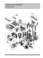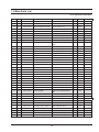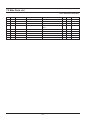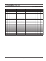
1
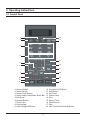
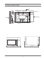
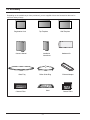
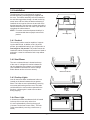
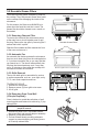
MICROWAVE OVEN
SMH7177STE
SERVICE
MICROWAVE OVEN
Manual
CONTENTS
1. Precaution
2. Specifications
3. Operating Instructions
4. Disassembly and Reassembly
5. Alignment and Adjustments
6. Troubleshooting
7. Exploded Views and Parts List
8. PCB Diagrams
9. Schematic Diagrams
10. Reference
SEA
Contents
1. Precaution . . . . . . . . . . . . . . . . . . . . . . . . . . . . . . . . . . . . . . . . . . . . . . . . . . . . . . . . . . . . . . . . . . . . . . . . . . . . . . . . . . . . . . . . . . . . . . . . . . . .1
1-1 Safety precautions . . . . . . . . . . . . . . . . . . . . . . . . . . . . . . . . . . . . . . . . . . . . . . . . . . . . . . . . . . . . . . . . . . . . . . . . . . . . . . . . . . . . . . . . .1
1-2 Special Servicing Precautions (Continued) . . . . . . . . . . . . . . . . . . . . . . . . . . . . . . . . . . . . . . . . . . . . . . . . . . . . . . . . . . . . . . . . . . . . . .2
1-3 Special High Voltage Precautions . . . . . . . . . . . . . . . . . . . . . . . . . . . . . . . . . . . . . . . . . . . . . . . . . . . . . . . . . . . . . . . . . . . . . . . . . . . . . .2
2. Specifications . . . . . . . . . . . . . . . . . . . . . . . . . . . . . . . . . . . . . . . . . . . . . . . . . . . . . . . . . . . . . . . . . . . . . . . . . . . . . . . . . . . . . . . . . . . . . . . . .3
2-1 Table of Specifications . . . . . . . . . . . . . . . . . . . . . . . . . . . . . . . . . . . . . . . . . . . . . . . . . . . . . . . . . . . . . . . . . . . . . . . . . . . . . . . . . . . . . .3
3. Operating Instructions . . . . . . . . . . . . . . . . . . . . . . . . . . . . . . . . . . . . . . . . . . . . . . . . . . . . . . . . . . . . . . . . . . . . . . . . . . . . . . . . . . . . . . . . . . .4
3-1 Control Panel . . . . . . . . . . . . . . . . . . . . . . . . . . . . . . . . . . . . . . . . . . . . . . . . . . . . . . . . . . . . . . . . . . . . . . . . . . . . . . . . . . . . . . . . . . . . .4
3-2 Features & External Views . . . . . . . . . . . . . . . . . . . . . . . . . . . . . . . . . . . . . . . . . . . . . . . . . . . . . . . . . . . . . . . . . . . . . . . . . . . . . . . . . . .5
3-3 Accessory . . . . . . . . . . . . . . . . . . . . . . . . . . . . . . . . . . . . . . . . . . . . . . . . . . . . . . . . . . . . . . . . . . . . . . . . . . . . . . . . . . . . . . . . . . . . . . . .6
3-4 Installation . . . . . . . . . . . . . . . . . . . . . . . . . . . . . . . . . . . . . . . . . . . . . . . . . . . . . . . . . . . . . . . . . . . . . . . . . . . . . . . . . . . . . . . . . . . . . . . .7
3-4-1 Caution! . . . . . . . . . . . . . . . . . . . . . . . . . . . . . . . . . . . . . . . . . . . . . . . . . . . . . . . . . . . . . . . . . . . . . . . . . . . . . . . . . . . . . . . . . . . . .7
3-4-2 Vent Blower . . . . . . . . . . . . . . . . . . . . . . . . . . . . . . . . . . . . . . . . . . . . . . . . . . . . . . . . . . . . . . . . . . . . . . . . . . . . . . . . . . . . . . . . . .7
3-4-3 Cooltop Lights . . . . . . . . . . . . . . . . . . . . . . . . . . . . . . . . . . . . . . . . . . . . . . . . . . . . . . . . . . . . . . . . . . . . . . . . . . . . . . . . . . . . . . . .7
3-4-4 Oven Light . . . . . . . . . . . . . . . . . . . . . . . . . . . . . . . . . . . . . . . . . . . . . . . . . . . . . . . . . . . . . . . . . . . . . . . . . . . . . . . . . . . . . . . . . . .7
3-5 Reusable Grease Filters . . . . . . . . . . . . . . . . . . . . . . . . . . . . . . . . . . . . . . . . . . . . . . . . . . . . . . . . . . . . . . . . . . . . . . . . . . . . . . . . . . . . .8
3-5-1 Removing Charcoal Filter . . . . . . . . . . . . . . . . . . . . . . . . . . . . . . . . . . . . . . . . . . . . . . . . . . . . . . . . . . . . . . . . . . . . . . . . . . . . . . .8
3-5-2 Automatic Fan . . . . . . . . . . . . . . . . . . . . . . . . . . . . . . . . . . . . . . . . . . . . . . . . . . . . . . . . . . . . . . . . . . . . . . . . . . . . . . . . . . . . . . . .8
3-5-3 Grille Removal . . . . . . . . . . . . . . . . . . . . . . . . . . . . . . . . . . . . . . . . . . . . . . . . . . . . . . . . . . . . . . . . . . . . . . . . . . . . . . . . . . . . . . . .8
3-5-4 Removing Oven From Wall . . . . . . . . . . . . . . . . . . . . . . . . . . . . . . . . . . . . . . . . . . . . . . . . . . . . . . . . . . . . . . . . . . . . . . . . . . . . . .8
4. Disassembly and Reassembly . . . . . . . . . . . . . . . . . . . . . . . . . . . . . . . . . . . . . . . . . . . . . . . . . . . . . . . . . . . . . . . . . . . . . . . . . . . . . . . . . . . .9
4-1 Replacement of High Voltage Transformer and Fan Motor Assembly. . . . . . . . . . . . . . . . . . . . . . . . . . . . . . . . . . . . . . . . . . . . . . . . . . .9
4-2 Replacement of Magnetron . . . . . . . . . . . . . . . . . . . . . . . . . . . . . . . . . . . . . . . . . . . . . . . . . . . . . . . . . . . . . . . . . . . . . . . . . . . . . . . . . .9
4-3 Replacement of Door Assembly . . . . . . . . . . . . . . . . . . . . . . . . . . . . . . . . . . . . . . . . . . . . . . . . . . . . . . . . . . . . . . . . . . . . . . . . . . . . . .10
4-3-1 Removal of Door “C” . . . . . . . . . . . . . . . . . . . . . . . . . . . . . . . . . . . . . . . . . . . . . . . . . . . . . . . . . . . . . . . . . . . . . . . . . . . . . . . . . .10
4-3-2 Removal of Door “E” . . . . . . . . . . . . . . . . . . . . . . . . . . . . . . . . . . . . . . . . . . . . . . . . . . . . . . . . . . . . . . . . . . . . . . . . . . . . . . . . . .10
4-3-3 Removal of Key Door & Spring . . . . . . . . . . . . . . . . . . . . . . . . . . . . . . . . . . . . . . . . . . . . . . . . . . . . . . . . . . . . . . . . . . . . . . . . . .10
4-3-4 Reassembly Test . . . . . . . . . . . . . . . . . . . . . . . . . . . . . . . . . . . . . . . . . . . . . . . . . . . . . . . . . . . . . . . . . . . . . . . . . . . . . . . . . . . . .11
4-4 Replacement of Main Fuse & H. V. Trans Fuse . . . . . . . . . . . . . . . . . . . . . . . . . . . . . . . . . . . . . . . . . . . . . . . . . . . . . . . . . . . . . . . . . . 11
4-5 Replacement of Drive Motor . . . . . . . . . . . . . . . . . . . . . . . . . . . . . . . . . . . . . . . . . . . . . . . . . . . . . . . . . . . . . . . . . . . . . . . . . . . . . . . . .11
4-6 Replacement of stirrer motor . . . . . . . . . . . . . . . . . . . . . . . . . . . . . . . . . . . . . . . . . . . . . . . . . . . . . . . . . . . . . . . . . . . . . . . . . . . . . . . .12
4-7 Removal of stirrer . . . . . . . . . . . . . . . . . . . . . . . . . . . . . . . . . . . . . . . . . . . . . . . . . . . . . . . . . . . . . . . . . . . . . . . . . . . . . . . . . . . . . . . . .12
4-8 Replacement of Control Circuit Board . . . . . . . . . . . . . . . . . . . . . . . . . . . . . . . . . . . . . . . . . . . . . . . . . . . . . . . . . . . . . . . . . . . . . . . . .13
4-8-1 Removal of Control Box . . . . . . . . . . . . . . . . . . . . . . . . . . . . . . . . . . . . . . . . . . . . . . . . . . . . . . . . . . . . . . . . . . . . . . . . . . . . . . .13
4-8-2 Removal of P.C.B Assembly . . . . . . . . . . . . . . . . . . . . . . . . . . . . . . . . . . . . . . . . . . . . . . . . . . . . . . . . . . . . . . . . . . . . . . . . . . . .13
5. Alignment and Adjustments . . . . . . . . . . . . . . . . . . . . . . . . . . . . . . . . . . . . . . . . . . . . . . . . . . . . . . . . . . . . . . . . . . . . . . . . . . . . . . . . . . . . . .14
5-1 High Voltage Transformer . . . . . . . . . . . . . . . . . . . . . . . . . . . . . . . . . . . . . . . . . . . . . . . . . . . . . . . . . . . . . . . . . . . . . . . . . . . . . . . . . . .14
5-2 Low Voltage Transformer . . . . . . . . . . . . . . . . . . . . . . . . . . . . . . . . . . . . . . . . . . . . . . . . . . . . . . . . . . . . . . . . . . . . . . . . . . . . . . . . . . .14
5-3 Magnetron . . . . . . . . . . . . . . . . . . . . . . . . . . . . . . . . . . . . . . . . . . . . . . . . . . . . . . . . . . . . . . . . . . . . . . . . . . . . . . . . . . . . . . . . . . . . . . .14
5-4 High Voltage Capacitor . . . . . . . . . . . . . . . . . . . . . . . . . . . . . . . . . . . . . . . . . . . . . . . . . . . . . . . . . . . . . . . . . . . . . . . . . . . . . . . . . . . . .15
5-5 High Voltage Diode . . . . . . . . . . . . . . . . . . . . . . . . . . . . . . . . . . . . . . . . . . . . . . . . . . . . . . . . . . . . . . . . . . . . . . . . . . . . . . . . . . . . . . . .15
5-6 Main Relay and Power Control Relay . . . . . . . . . . . . . . . . . . . . . . . . . . . . . . . . . . . . . . . . . . . . . . . . . . . . . . . . . . . . . . . . . . . . . . . . . .15
5-7 Adjustment of Primary Switch, Door Sensing Switch and Monitor Switch . . . . . . . . . . . . . . . . . . . . . . . . . . . . . . . . . . . . . . . . . . . . . .15
5-8 Vent Exhaust Blower Motor. . . . . . . . . . . . . . . . . . . . . . . . . . . . . . . . . . . . . . . . . . . . . . . . . . . . . . . . . . . . . . . . . . . . . . . . . . . . . . . . . .16
5-9 Thermal Cutout (TCO’S) . . . . . . . . . . . . . . . . . . . . . . . . . . . . . . . . . . . . . . . . . . . . . . . . . . . . . . . . . . . . . . . . . . . . . . . . . . . . . . . . . . . .17
5-9-2 Replacement of Flame Sensor . . . . . . . . . . . . . . . . . . . . . . . . . . . . . . . . . . . . . . . . . . . . . . . . . . . . . . . . . . . . . . . . . . . . . . . . . .17
5-9-1 Oven Thermal Cutout (Flame sensor) . . . . . . . . . . . . . . . . . . . . . . . . . . . . . . . . . . . . . . . . . . . . . . . . . . . . . . . . . . . . . . . . . . . . .17
5-9-3 Bottom Thermal Cutout . . . . . . . . . . . . . . . . . . . . . . . . . . . . . . . . . . . . . . . . . . . . . . . . . . . . . . . . . . . . . . . . . . . . . . . . . . . . . . . .18
5-9-4 Magnetron Thermal Cutout . . . . . . . . . . . . . . . . . . . . . . . . . . . . . . . . . . . . . . . . . . . . . . . . . . . . . . . . . . . . . . . . . . . . . . . . . . . . .18
5-9-5 Magnetron Thermal Cutout . . . . . . . . . . . . . . . . . . . . . . . . . . . . . . . . . . . . . . . . . . . . . . . . . . . . . . . . . . . . . . . . . . . . . . . . . . . . .19
5-10 Sensor. . . . . . . . . . . . . . . . . . . . . . . . . . . . . . . . . . . . . . . . . . . . . . . . . . . . . . . . . . . . . . . . . . . . . . . . . . . . . . . . . . . . . . . . . . . . . . . . .19
5-11 Output Power of Magnetron . . . . . . . . . . . . . . . . . . . . . . . . . . . . . . . . . . . . . . . . . . . . . . . . . . . . . . . . . . . . . . . . . . . . . . . . . . . . . . . .20
5-12 Procedure for Measurement of Microwave Energy Leakage . . . . . . . . . . . . . . . . . . . . . . . . . . . . . . . . . . . . . . . . . . . . . . . . . . . . . . .21
5-13 Check for Microwave Leakage . . . . . . . . . . . . . . . . . . . . . . . . . . . . . . . . . . . . . . . . . . . . . . . . . . . . . . . . . . . . . . . . . . . . . . . . . . . . . .21
5-14 Note on Measurement . . . . . . . . . . . . . . . . . . . . . . . . . . . . . . . . . . . . . . . . . . . . . . . . . . . . . . . . . . . . . . . . . . . . . . . . . . . . . . . . . . . .21
5-15 Leakage Measuring Procedure . . . . . . . . . . . . . . . . . . . . . . . . . . . . . . . . . . . . . . . . . . . . . . . . . . . . . . . . . . . . . . . . . . . . . . . . . . . . . .21
6. Troubleshooting . . . . . . . . . . . . . . . . . . . . . . . . . . . . . . . . . . . . . . . . . . . . . . . . . . . . . . . . . . . . . . . . . . . . . . . . . . . . . . . . . . . . . . . . . . . . . . .22
6-1 Electrical Malfunction
6-2 Error Code Numbering Rule . . . . . . . . . . . . . . . . . . . . . . . . . . . . . . . . . . . . . . . . . . . . . . . . . . . . . . . . . . . . . . . . . . . . . . . . . . . . . . . . .22
7. Exploded Views and Parts List . . . . . . . . . . . . . . . . . . . . . . . . . . . . . . . . . . . . . . . . . . . . . . . . . . . . . . . . . . . . . . . . . . . . . . . . . . . . . . . . . . .24
7-1 Exploded Views . . . . . . . . . . . . . . . . . . . . . . . . . . . . . . . . . . . . . . . . . . . . . . . . . . . . . . . . . . . . . . . . . . . . . . . . . . . . . . . . . . . . . . . . . .24
7-2 Main Parts List . . . . . . . . . . . . . . . . . . . . . . . . . . . . . . . . . . . . . . . . . . . . . . . . . . . . . . . . . . . . . . . . . . . . . . . . . . . . . . . . . . . . . . . . . . .25
7-3 Control & Door Parts List . . . . . . . . . . . . . . . . . . . . . . . . . . . . . . . . . . . . . . . . . . . . . . . . . . . . . . . . . . . . . . . . . . . . . . . . . . . . . . . . . . .28
7-4 Standard Parts List . . . . . . . . . . . . . . . . . . . . . . . . . . . . . . . . . . . . . . . . . . . . . . . . . . . . . . . . . . . . . . . . . . . . . . . . . . . . . . . . . . . . . . . .29
8. P.C.B Diagrams . . . . . . . . . . . . . . . . . . . . . . . . . . . . . . . . . . . . . . . . . . . . . . . . . . . . . . . . . . . . . . . . . . . . . . . . . . . . . . . . . . . . . . . . . . . . . . .30
8-2 P.C.B Parts List . . . . . . . . . . . . . . . . . . . . . . . . . . . . . . . . . . . . . . . . . . . . . . . . . . . . . . . . . . . . . . . . . . . . . . . . . . . . . . . . . . . . . . . . . . .31
9. Schematic Diagrams . . . . . . . . . . . . . . . . . . . . . . . . . . . . . . . . . . . . . . . . . . . . . . . . . . . . . . . . . . . . . . . . . . . . . . . . . . . . . . . . . . . . . . . . . . .33
10. Reference . . . . . . . . . . . . . . . . . . . . . . . . . . . . . . . . . . . . . . . . . . . . . . . . . . . . . . . . . . . . . . . . . . . . . . . . . . . . . . . . . . . . . . . . . . . . . . . . . .34
10-1 Model name standard . . . . . . . . . . . . . . . . . . . . . . . . . . . . . . . . . . . . . . . . . . . . . . . . . . . . . . . . . . . . . . . . . . . . . . . . . . . . . . . . . . . . .34
10-2 Customer inquiry cases and countermeasures . . . . . . . . . . . . . . . . . . . . . . . . . . . . . . . . . . . . . . . . . . . . . . . . . . . . . . . . . . . . . . . . .35
-2-
PRECAUTIONS TO BE OBSERVED BEFORE AND
DURING SERVICING TO AVOID POSSIBLE
EXPOSURE TO EXCESSIVE MICROWAVE ENERGY
(a) Do not operate or allow the oven to be
operated with the door open.
(b) Make the following safety checks on all
ovens to be serviced before activating the
magnetron or other microwave source,
and make repairs as necessary:
(1) Interlock operation,
(2) proper door closing,
(3) seal and sealing surfaces (arcing,
wear, and other damage),
(4) damage to or loosening of hinges and
latches,
(5) evidence of dropping or abuse.
(c) Before turning on microwave power for
any service test or inspection within the
microwave generating compartments,
check the magnetron, wave guide or
transmission line, and cavity for proper
alignment, integrity, and connections.
(d) Any defective or misadjusted components
in the interlock, monitor, door seal, and
microwave generation and transmission
systems shall be repaired, replaced, or
adjusted by procedures described in this
manual before the oven is released to the
owner.
(e) A Microwave leakage check to verify
compliance with the Federal performance
standard should be performed on each
oven prior to release to the owner.
1. Precaution
Follow these special safety precautions. Although the microwave oven is completely safe during ordinary use,
repair work can be extremely hazardous due to possible exposure to microwave radiation, as well as potentially
lethal high voltages and currents.
1-1 Safety precautions (
)
1. All repairs should be done in accordance with the
procedures described in this manual. This product
complies with Federal Performance Standard 21
CFR Subchapter J(DHHS).
10. Service technicians should remove their watches
while repairing an MWO.
11. To avoid any possible radiation hazard, replace
parts in accordance with the wiring diagram. Also,
use only the exact replacements for the following
parts: Primary and secondary interlock switches,
interlock monitor switch.
2. Microwave emission check should be performed to
prior to servicing if the oven is operative.
3. If the oven operates with the door open :
Instruct the user not to operate the oven and contact the manufacturer and the center for devices
and radiological health immediately.
12. If the fuse is blown by the Interlock Monitor Switch:
Replace all of the following at the same time: Primary, door sensing switch and power relay, as well
as the Interlock Monitor Switch. The correct adjustment of these switches is described elsewhere in
this manual. Make sure that the fuse has the correct rating for the particular model being repaired.
4. Notify the Central Service Center if the microwave
leakage exceeds 5 mW/cm2.
5. Check all grounds.
6. Do not power the MWO from a “2-prong” AC cord.
Be sure that all of the built-in protective devices are
replaced. Restore any missing protective shields.
7. When reinstalling the chassis and its assemblies,
be sure to restore all protective devices, including:
nonmetallic control knobs and compartment covers.
8. Make sure that there are no cabinet openings
through which people --particularly children --might
insert objects and contact dangerous voltages.
Examples: Lamp hole, ventilation slots.
13. Design Alteration Warning:
Use exact replacement parts only, i.e., only those
that are specified in the drawings and parts lists
of this manual. This is especially important for the
Interlock switches, described above. Never alter
or add to the mechanical or electrical design of the
MWO. Any design changes or additions will void
the manufacturer’s warranty. Always unplug the
unit’s AC power cord from the AC power source
before attempting to remove or reinstall any component or assembly.
14. Never defeat any of the B+ voltage interlocks.
Do not apply AC power to the unit (or any of its
assemblies) unless all solid-state heat sinks are
correctly installed.
9. Inform the manufacturer of any oven found to have
emission in excess of 5 mW/cm2, Make repairs to
bring the unit into compliance at no cost to owner
and try to determine cause. Instruct owner not to
use oven until it has been brought into compliance.
15. Some semiconductor (“solid state”) devices are
easily damaged by static electricity. Such components are called Electrostatically Sensitive Devices
(ESDs). Examples include integrated circuits and
field -effect transistors.
CENTRAL SERVICE CENTER
Immediately before handling any semiconductor
components or assemblies, drain the electrostatic
charge from your body by touching a known earth
ground.
-1-
1-2 Special Servicing Precautions (Continued)
16. Always connect a test instrument’s ground lead
to the instrument chassis ground before connecting the positive lead; always remove the
instrument’s ground lead last.
19. Use replacement components that have the
same ratings, especially for flame resistance and
dielectric strength specifications. A replacement
part that does not have the same safety characteristics as the original might create shock, fire or
other hazards.
17. When checking the continuity of the witches or
transformer, always make sure that the power is
OFF, and one of the lead wires is disconnected.
18. Components that are critical for safety are indicated in the circuit diagram by shading,
or
.
1-3 Special High Voltage Precautions
1. High Voltage Warning !
Do not attempt to measure any of the high voltages --this includes the filament voltage of the
magnetron. High voltage is present during any
cook cycle.
High Voltage Capacitor
Before touching any components or wiring, always
unplug the oven and discharge the high voltage
capacitor (See Figure 1-1)
2. The high-voltage capacitor remains charged about
30 seconds after disconnection. Short the negative terminal of the high-voltage capacitor to the
oven chassis. (Use a screwdriver.)
3. High voltage is maintained within specified limits
by close-tolerance, safety-related components
and adjustments. If the high voltage exceeds the
specified limits, check each of the special components.
Fig. 1-1 Discharging High Voltage Capacitor
PRECAUTION
PRECAUTION
There exists HIGH VOLTAGE ELECTRICITY with
high current capabilities in the circuits of the HIGH
VOLTAGE TRANSFORMER secondary and filament terminals. It is extremely dangerous to work
on or near these circuits with the oven energized.
DO NOT measure the voltage in the high voltage
circuit including filament voltage of magnetron.
Never touch any circuit wiring with your hand nor
with uninsulated tool during operation.
PRECAUTION
Servicemen should remove their watches whenever working close to or replacing the magnetron.
-2-
2. Specifications
2-1 Table of Specifications
TIMER
99 MINUTES 99 SECONDS
POWER SOURCE
120VAC 60Hz
POWER CONSUMPTION
MICROWAVE : 1,650W
OUTPUT POWER
FROM 100 TO 1100W(10 LEVEL POWER)
(IEC-705 TEST PROCEDURE)
OPERATING FREQUENCY
2,450MHz
MAGNETRON
OM75P(10)ERHN
COOLING METHOD
COOLING FAN MOTOR
OVEN CAVITY DIMENSIONS
207/8”(W) x 109/32”(H) x 141/32”(D) mm
OUTSIDE DIMENSIONS
297/8”(W) x 1515/16”(H) x 165/32”(D) mm
NET WEIGHT
58.4 lbs
SHIPPING WEIGHT
64.4 lbs
-3-
3. Operating Instructions
3-1 Control Panel
1
13
2
11
3
4
17
5
12
6
8
7
15
16
9
14
10
18
1. Sensor Reheat
2. Power Defrost
3. Sensor Cook Buttons
4. Handy Helper, Kids Meals, Snack Bar
5. More/Less
6. Number Buttons
7. Power Level
8. Clock am/pm
9. Light On/Night/Off Button
-4-
10. Turntable On/Off Button
11. One Minute +
12. My Choice
13. Custom Cook
14. Start
15. Kitchen Timer
16. Pause/Cancel
17. Help
18. Vent Fan Turbo/Hi/Low/Off Button
3-2 Features & External Views
Grill
Door
Ventilation Holes
Oven Light
Safety Interlock Holes
Control Panel
Handle
Glass Tray Guide Roller Intake Holes
404.8mm
Door Key
758.8mm
410.3mm
-5-
3-3 Accessory
Depending on the model that you have purchased, you are supplied with several accessories that can be
used in a variety of ways.
Registration Card
Owner’s Manual
Glass Tray
Top Template
Installation
Instructions
Roller Guide Ring
Shelf
Charcoal Filter
-6-
Wall Template
Hardware-Kit
Exhaust Adaptor
Grease Filters
3-4 Installation
The Microwave Oven is supported by a special
bracket assembly (mounting system) supplied with
the oven. The bracket assembly must be mounted to
the wall with toggle bolts through the wall, and a lag
screw into a wall stud. After the bracket assembly is
installed, the unit can be slid over the two rails of the
bracket assembly. Two bolts are run down through the
cabinet bottom and into the oven case to pull the oven
up against the cabinet bottom.
NOTE : For easier removal and personal safety it is
recommended that two people remove this
product.
Mounting Plate
3-4-1 Caution!
The mounting surface must be capable of supporting the cabinet load, in addition to the 64 pound
product, plus additional loads of up to 50 pounds or a
total weight of 114 pounds. This product cannot be
installed to cabinet arrangements such as an island or
peninsula. It must be mounted to both a top cabinet
and wall.
3-4-2 Vent Blower
The vent or exhaust blower is located at the top
of the oven. It is shipped for vertical exhaust but
can be changed to rear exhaust or recirculating
(See installation instrustions on how to change
and/or blower section on how to remove).
REMOVE SCREWS
3-4-3 Cooltop Lights
One 40-watt screw base incandescent bulbs are
located on the bottom between the two grease
filters. The bulbs are user replaceable by removing
one screw and lowering access cover. The bulbs
could be difficult to remove when replaced for the
first time. a silicone glue is used to secure them
during shipping.
3-4-4 Oven Light
A 40-watt screw base incandescent bulb is located
in the top of the oven cavity at the front.
It is user replaceable by removing the top grill
(2 screws. On the front of outer case.). The bulb
is then accessible by removing a metal cover (1
screw).
-7-
3-5 Reusable Grease Filters
The metal filter trap grease released by foods on
the cooktop. They also prevent flames from foods
on the cooktop from damaging the inside of the
microwave.
Charcoal Filter
For this reason, the filters must ALWAYS be in
place when the hood the vent fan is used. The
grease filter should be cleaned once a month, or
as needed.
3-5-1 Removing Charcoal Filter
To remove the charcoal filter, disconnect power
at the main fuse or circuit breaker panel or pull
the plug. Remove the top grille by removing the 2
screws that hold it in place.
Reusable Grease Filters
Screws
Slide the filter towards the filter towards the front
of the oven and remove it.
3-5-2 Automatic Fan
An automatic fan feature protects the microwave
from too much heat rising from the cooktop below
it. If you have turned the fan on you may find that
you cannot turn it. The fan will automatically turn
off when the internal parts are cool. If may stay
on for 30 minutes or more after the cooktop and
microwave controls are turned off.
3-5-3 Grille Removal
The top full-width grille is removable for service
to some components, such as : oven light, cavity
T.C.O, vent motor capacitor and fuse.
TO REMOVE GRILLE :
1. Disconnect oven power.
2. Remove screws (2) from grille outer case.
3. Lift off grille.
3-5-4 Removing Oven From Wall
(2 Peuple Required))
Oven is hooked on metal tabs at bottom of wall
mounting plate and fastened to cabinet by (3) top
cabinet bolts.
CAUTION : Oven weights 63.1 lbs. Requires 2
people for removal.
1. Disconnect power cord. Top vented modelsdisconnect duct and remove damper assembly.
2. Remove (3) top cabinet bolts.
3. Pull unit forward slowly providing adequate
support to prevent dropping unit during removal of last top cabinet bolts.
-8-
Remove 2 grille screws to remove the grill
4. Disassembly and Reassembly
MAGNETRON, MOTOR ASSEMBLY, VENT BLOWER AND HIGH VOLTAGE TRANSFORMER
Oven must be removed from wall.
REMOVING OVEN FROM WALL (2 PEOPLE REQUIRED)
Oven is hooked on metal tabs at bottom of wall mounting plate and to cabinet by (3) top cabinet bolts.
4-1 Replacement of High Voltage Transformer and Fan Motor Assembly.
Disconnect oven power.
Remove Grille & Control Box Assembly.
1. Discharge the high voltage capacitor.
2. Disconnect all the leads.
3. Remove (2) screws from the fan motor assembly.
4. Remove (3) screws from the duct-side.
5. Remove the duct-side.
6. Take out the fan motor.
7. Remove (4) Screws from the H.V.Trans.
8. Take out the H.V.Trans.
SCREW
SCREW(TOP)
SCREW
(BACK)
SCREW
XMER SCREWS
(2 EACH SIDE)
SCREW
(SIDE)
(DUCT SIDE)
4-2 Replacement of Magnetron
Remove the magnetron including the shield case,
permanent magnet, choke coils and capacitors (all of
which are contained in one assembly).
MGT NUTS (4)
1. Disconnect all lead wires from the magnetron.
2. Remove nuts (4) securing the magnetron to the
wave guide.
3. Take out the magnetron very carefully.
NOTE 1: When removing the magnetron, make
sure that it’s antenna does not hit any
adjacentparts, or it may be damaged.
NOTE 2: When replacing the magnetron, be sure
to remount the magnetron gasket in the
correct position and make sure the gasket
is in good condition.
CAUTION !
During replacement, be certain R.F. anode gasket is in
place around anode stub.
PERFORM MICROWAVE LEAKAGE TEST
-9-
4-3 Replacement of Door Assembly
4-3-1 Removal of Door “C”
Open the door and remove the door by
pulling up from hinge holes.
Door "A"
Door "C"
Door “E”
4-3-2 Removal of Door “E”
Following the procedure as shown in the figure,
insert and bend a thin metal plate between Door
“E” and Door “A” until you hear the ‘tick’ sound.
● Insertion depth of the thin metal plate should be
0.5mm or less.
4-3-3 Removal of Key Door & Spring
Remove pin hinge from Door “E”.
Detach spring from Door “E” and key door.
Door "E"
Key Door
Spring
- 10 -
4-3-4 Reassembly Test
After replacement of the defective component parts of the door, reassemble it and follow the instructions below for proper installation and adjustment so as to prevent an excessive microwave leakage.
1. When mounting the door to the oven, be sure to adjust the door parallel to the bottom line of the oven face
plate by moving the upper hinge and lower hinge in the direction necessary for proper alignment.
2. Adjust so that the door has no play between the inner door surface and oven front surface. If the door assembly is not mounted properly, microwave energy may leak from the space between the door and oven.
3. Do the microwave leakage test.
4-4 Replacement of Main Fuse & H. V. Trans Fuse
The fuse is located behind the control panel mounted
to the installation bracket.
1. Disconnect power and remove grille.
2. Remove a screw that secure the installation
bracket.
MAIN FUSE
1. When 20A fuse blows out by the operation of
interlock monitor switch failure, replace the
primary interlock switch, door sensing switch,
interlock monitor switch and power relay.
2. When the above 3 switches operate properly,
check if any other part such as the control
circuit board, blower motor or high voltage
transformer is defective.
MAIN FUSE
FUSE & FUSE HOLDER
H. V. TRANS FUSE
1. When 20 Amp. fuse is blown due to operation of the H. V. Trans fall mode, the H. V. Trans Fuse must be
replaced.
4-5 Replacement of Drive Motor
1. Disconnect power.
2. Remove the three screws at the assy base bottom.
3. Remove the plastic cover (fixed with a screw) that
covers the motor.
4. Remove all of the wires connected.
5. Remove a screw from the motor.
6. Turn the motor to the right and remove it.
7. After replacing the motor, you should re-install it on
the accurate position of the coupler.
8. Assembling is in the reverse order to disassebling.
BASE PLATE
DRIVE MOTOR
- 11 -
Screw(1)
4-6 Replacement of stirrer motor
1. Disconnect power and remove grille screws(2).
2. Remove grille and the bracket duct upper screw(1).
3. Remove the bracket duct upper and disconnect the
stirrer motor wire.
4. Remove stirrer motor screws(1) and lift up stirrer
motor after turn left.
STIRRER MOTOR
4-7 Removal of stirrer
The stirrer is located on the upper side of the cavity. The oven uses a top feed wave guide.
1. Disconnect power and open the door.
2. Remove the clip and turn the stirrer cover left.
3. Remove stirrer cover and the stirrer will come with
it.
4. Replace the clip if the clip head broken.
CLIP
COVER STIRRER
STIRRER ASSEMBLY
COVER STIRRER
- 12 -
4-8 Replacement of Control Circuit Board
4-8-1 Removal of Control Box
1. Disconnect power and remove grille.
2. Remove a screw securing the control box
assembly.
3. Be sure to ground any static electric charge in
your body and never touch the control circuit.
4. Disconnect the connectors from the control
circuit board.
4-8-2 Removal of P.C.B Assembly
1. Pull the lever end of the plastic fastener and
remove the Flexible Printed Circuit(FPC) of
membrane panel.
Screw
FPC
connector
2. Remove screws (3) securing the control circuit
board.
3. Lift up the control circuit board from the Ass’y
control box.
Screw
4. When reconnecting the FPC connector, make
sure that the holes on the connector are properly
engaged with the hooks on the Plastic Fastener.
- 13 -
5. Alignment and Adjustments
PRECAUTION
1. High voltage is present at the high voltage terminals during any cook cycle.
2. It is neither necessary nor advisable to attempt measurement of the high voltage.
3. Before touching any oven components or wiring, always unplug the oven from its power source and discharge the high voltage capacitor.
5-1 High Voltage Transformer
1. Remove connectors from the transformer terminals
and check continuity.
2. Normal resistance readings are as follows:
(Room temperature = 20°C)
Filament Terminals
Secondary
Terminal
SHV-U1870AR
Secondary
80.5 Ω +2%
Filament
Shows Continuity
Primary
1100W 0.330 Ω + 2%
1000W 0.375 Ω + 2%
Primary
Terminals
5-2 Low Voltage Transformer
1. The low voltage transformer is located on the
control circuit board.
2. Remove the low voltage transformer from the
PCB Ass’y and check continuity.
3. Normal resistor reading is shown in the table.
Resistance
Terminals
SLV-1350U(P)
1~2(Input)
127.7 Ω
4~5(Output 2.7V)
1.8 Ω
6~7(Output 7.0V)
2.0 Ω
7~8(Output 19.0V)
4.8 Ω
5-3 Magnetron
1. Continuity checks can indicate only an open
filament or a shorted magnetron. To diagnose an
open filament or shorted magnetron :
2. Isolate the magnetron from the circuit by
disconnecting its leads.
3. A continuity check across the magnetron filament
terminals should indicate one ohm or less.
4. A continuity check between each filament terminal
and magnetron case should read open.
Magnetron Antenna
Gasket Plate
Cooling Fins
- 14 -
5-4 High Voltage Capacitor
1. Check continuity of the capacitor with the meter set at the highest resistance scale.
2. Once the capacitor is charged, a normal capacitor shows continuity for a short time, and then indicates 9MΩ.
3. A shorted capacitor will show continuous continuity.
4. An open capacitor will show constant 9MΩ.
5. Resistance between each terminal and chassis should read infinite.
5-5 High Voltage Diode
1. Isolate the diode from the circuit by disconnecting its leads.
2. With the ohm-meter set at the highest resistance scale, measure across the diode terminals. Reverse the
meter leads and read the resistance. A meter with 6V, 9V or higher voltage batteries should be used to check
the front-to back resistance of the diode (otherwise an infinite resistance may be read in both directions).
The resistance of a normal diode will be infinite in one direction and several hundred KΩ in the other
direction.
5-6 Main Relay and Power Control Relay
1. The relays are located on the PCB Ass’y. Isolate them from the main circuit by disconnecting the leads.
2. Operate the microwave oven with a water load in the oven. Set the power level set to high.
3. Check continuity between terminals of the relays after the start pad is pressed.
5-7 Adjustment of Primary Switch, Door Sensing Switch and Monitor Switch
PRECAUTION
For continued protection against radiation hazard, replace parts in accordance with the wiring diagram and be sure
to use the correct part number for the following switches: Primary and secondary interlock switches, and the interlock monitor switch (replace all together). Then follow the adjustment procedures below. After repair and adjustment, be sure to check the continuity of all interlock switches and the interlock monitor switch.
1. When mounting Primary switch and Interlock Monitor switch to Latch Body, consult the figure.
2. No specific adjustment during installation of Primary switch and Monitor switch to the latch body is
necessary.
3. When mounting the Latch Body to the oven assembly, adjust the Latch Body by moving it so that the
oven door will not have any play in it. Check for play
in the door by pulling the door assembly. Make sure
that the latch keys move smoothly after adjustment
is completed. Completely tighten the screws holding
the Latch Body to the oven assembly.
4. Reconnect to Monitor switch and check the continuity of the monitor circuit and all latch switches again
by following the components test procedures.
5. Confirm that the gap between the switch housing
and the switch actuator is no more than 0.5mm
when door is closed.
6. Interlock Switch Replacement - When replacing
faulty switches, be sure switch mounting tabs are
not bent, broken or otherwise deficient in their ability to secure the switches in place.
- 15 -
Primary Interlock Switch
Body Latch
Interlock Monitor
Switch
Door Sensing Switch
(Secondary
Interlock Switch)
Lever Switch(A)
Primary Interlock S/W
Monitor switch(COM-NC)
Door Sensing S/W
(Secondary Interlock S/W)
Door Open
Door Closed
∞
0
∞
0
∞
0
5-8 Vent Exhaust Blower Motor
THIS COMPONENT REQUIRE REMOVAL OF
MICROWAVE OVEN FROM INSTALLATION FOR
SERVICING.
The blower is a two speed (HI-LO) capacitor run
blower assembly located on top of the microwave oven. The blower is operated by low
voltage relays located on the smart board.
The blower motor has 3 winding which can be
tested for continuity from the front by removing
the top grille and opening the control panel.
RUN CAPACITOR
The run capacitor is located behind the top
grille above the control area. The capacitor is
used for more torque and electrical phasing.
Without the capacitor the blower might run but
would be much slower.
Damper ASM
Blower ASM
TO TEST THE CAPACITOR
1. Remove grille, discharge capacitor and disconnect
one capacitor lead.
2. Make appropriate capacitor check (with analog
meter needle should rise then fall, cap is charging
then discharging).
TO TEST BLOWER WINDINGS:
1. Disconnect power and remove grille.
2. Open control panel and discharfe capacitor.
3. Disconnent two wires to run capacitor. Continuity
test across the two wires should ve approximately
75 ohms of resistance. This test allows you to read
across all three windings at the same time.
TO REMOVE VENT BLOWER
1. Remove unit from its installation.
2. Remove 5 screws securing damper and motor assembly to top and back of unit and lift off.
(1 screw is located under damper.)
3. Disconnect blower plug.
NOTE: Place blower wires in routing slots to avoid
pinching of wires.
- 16 -
5-9 Thermal Cutout (TCO’S)
There are 4 different thermal cutouts in this unit with 4 different purposes. They are :
1. Oven thermal cutout (flame sensor), on cavity top.
2. Hood thermal cutout, inside control area on duct.
3. Bottom thermal cutout, on floor of control area.
4. Magnetron thermal cutout, on magnetron.
5-9-1 Oven Thermal Cutout (Flame sensor)
The oven thermal cutout(Cavity TCO) is located
on the top side of the oven cavity beside exhaust
duct with a temperature rating of 248OF(120OC)
and is non-resetable.
The cutout is tightly held to the top of the oven
cavity by duct-upper.
OVEN THERMAL CUTOUT
STIRRER MOTOR
5-9-2 Replacement of Flame Sensor
Disconnect oven power. Remove Grille & Panel-outer.
1. Remove screws(3) securing the duct upper.
SCREW
T.C.O
SCREW
Screw
2. Loft up the duct upper from the cavity.
3. Disconnect two wire leads.
4. Press the top of the thermal cutout and pull out it in
the duct upper.
Press the Flame Sensor
After press
- 17 -
5-9-3 Bottom Thermal Cutout
This cutout will protect the touch control from excessive heat by turning the vent fan on at low speed. If the
surface units of the range are used for long periods of
time heat will build up and could damage the microwave control. In order to prevent this a thermal cutout
is installed on the duct behind the control. This cutout
will close (158°F/70°C - vent fan energized)and open
(104°F/40°C - vent fan de-energized) depending on
temperatures it sense.
To Remove hood Thermal Cutout :
1. Disconnect power and remove grille.
2. Remove control box assembly.
3. Remove two wire leads and unscrew one screw
capturing cutout on base plate.
NOTE : It this cutout were to open it would be difficult
to detect. The only time it functions is during
an overheat condition. It will be normally open
when checked with an ohmmeter.
5-9-4 Magnetron Thermal Cutout
HOOD THERMAL CUTOUT
BOTTOM THERMAL CUTOUT
HOOD THERMAL CUTOUT
THIS COMPONENT REQUIRE REMOVAL OF
MICROWAVE OVEN FROM INSTALLATION FOR
SERVICING.
During a fire on the stove the heat could be intense
enough to close the Hood Thermal Cutout and force
the fan to run. While at moderate high temperature we
do want it to run, however during a fire it is advantageous to NOT have the vent fan running. So if a fire were
to start on the stove top the Bottom Thermal Cutout
would open at 248°F(120°C) and remove all power to
the microwave oven. This cutout is designed to not be
resetable.
To Remove Bottom Thermal Cutout :
1. Disconnect power and remove grille.
2. Remove control box assembly.
3. Remove two wire leads and unscrews one screw
capturing cutout on base plate.
- 18 -
BOTTOM THERMAL CUTOUT
5-9-5 Magnetron Thermal Cutout
The magnetron thermal cutout is located above the
leads to the magnetrons. It is designed to prevent
damage to the magnetron if an overheated condition
develops in the tube to cooling fan failure, obstructed
air ducts, dirty or blocked air intake.
Under normal operation, the magnetron thermal cutout
remains closed. However, when abnormally high
temperatures are reached within the magnetron, the
magnetron thermal cutout will open at 320°F(160OC)
causing the oven to shut down. After the temperature
drops to 140°F(60°C) it will reset and cooking will be
able to resume.
To Remove Magnetron Thermal Cutout :
1. See ‘Removing Magnetron’.
MAGNETRON THERMAL CUTOUT
MAGNETRON
5-10 Sensor
The Sensor Cooking Function uses a special gas
sensor which detects both humidity(steam) and
hydrocarbons(food odors) during the cooking
process. Before conducting either of the sensor
tests below, ensure the unit is plugged into a will
outlet for at least 5 minutes. If already plugged
in, proceed. The sensor is a plug-in device
located in the vent area at the top left hand
corner of the cavity behind the grille.
VENT MOTOR
To Service :
1. Disconnect power and remove grille.
2. Separate retainer from receptacle and
unplug sensor.
GAS SENSOR
SENSOR COOKING TEST
1. Place 1/3 cup tap water in oven.
2. Touch potato , the oven starts immediately.
3. Control Beeps and Shuts off.
4. Touch Pause/Cancel .
1) Test OK - Normal
2) Test Fails - Check Sensor. See Sensor Test Below.
SENSOR TEST (QUICK TEST)
1. With 2 fingers touch and hold the following pads at the same time :
Power Defrost and Sensor Reheat
2. Observe diagnostic number in display (Numbers approximate).
● 15-185 (Normal-verify with “detection test” )
● 213 or Higher (Sensor failed to open, sensor
unplugged, wiring or smart board.)
● Less then 6 (shorted sensor, or smart board).
NOTE : Only heater terminals ( H ; Black and Red leads) can be checked with ohmmeter(30Ω).
CAUTION : DO NOT ATTEMPT TO CHECK SENSOR TERMINALS (White and Orange leads).
♣ CAN DAMAGE SENSOR.
- 19 -
5-11 Output Power of Magnetron
CAUTION
MICROWAVE RADIATION
PERSONNEL SHOULD NOT ALLOW EXPOSURE TO MICROWAVE RADIATION FROM MICROWAVE GENERATOR OR OTHER PARTS CONDUCTING MICROWAVE ENERGY.
The output power of the magnetron can be measured by performing a water temperature rise test.
Equipment needed :
* Two 1-liter cylindrical borosilicate glass vessel (Outside diameter 190 mm)
* One glass thermometer with mercury column
NOTE: Check line voltage under load. Low voltage will lower the magnetron output. Make all temperature and time tests
with accurate equipment.
1. Fill the one liter glass vessel with water.
2. Stir water in glass vessel with thermometer, and record glass vessel’s temperature (“T1”, 10±1°C).
3. After moving the water into another glass vessel, place it in the center of the cooking tray. Set the oven to high power and
operate for 41 seconds exactly. (3 seconds included as a holding time of magnetron oscillation:)
4. When heating is finished, stir the water again with the thermometer and measure the temperature (“T2”).
5. Subtract T1 from T2. This will give you the water temperature rise. (∆T)
6. The output power is obtained by the following formula;
Output Power =
4.187 x 1000 x ∆T+0.55xMcx(T2 -T1)
38
38 : Heating Time (sec)
41 : Counting Time (sec)
4.187 : Coefficient for Water
1000 : Water (cc)
∆T : Temperature Rise (T2-T1)
To : Room Temperature
Mc : Cylindrical borosilicate glass weight
7. Normal temperature rise for this model is 9.9°C to 10.3°C at ‘HIGH’.
NOTE 1: Variations or errors in the test procedure will cause a variance in the temperature rise.
Additional power test should be made if temperature rise is marginal.
NOTE 2: Output power in watts is computed by multiplying the temperature rise (step 5) by a factor of 91 times the of
centigrade temperature.
- 20 -
5-12 Procedure for Measurement of Microwave Energy Leakage
1) Pour 275±15cc of 20±5°C(68±9°F) water in a beaker
which is graduated to 600cc, and place the beaker in
the center of the oven.
2) Start to operate the oven and measure the leakage by
using a microwave energy survey meter.
3) Set survey meter with dual ranges to 2,450MHz.
4) When measuring the leakage, always use the 2 inch
spacer cone with the probe. Hold the probe perpendicular
to the cabinet door. Place the spacer cone of the probe on
the door and/or cabinet door seam and move along the
seam, the door viewing window and the exhaust openings
moving the probe in a clockwise direction at a rate of 1 inch/sec. If the leakage testing of the cabinet door
seam is taken near a corner of the door, keep the probe perpendicular to the areas making sure that the
probe end at the base of the cone does not get closer than 5cm to any metal. If it gets closer than 5cm,
erroneous readings may result.
5) Measured leakage must be less than 4mW/cm2 , after repair or adjustment.
Maximum allowable leakage is 5mW/cm2 .
4mW/cm2 is used to allow for measurement and meter accuracy
5-13 Check for Microwave Leakage
1. Remove the outer panel.
2. Pour 275±15cc of 20±5°C(68±9°F) water in a beaker
which is graduated to 600cc, and place the beaker
in the center of the oven.
3. Start the oven at the highest power level.
4. Set survey meter dual ranges to 2,450MHz.
5. Using the survey meter and spacer cone as described
above, measure near the opening of magnetron, the
surface of the air guide and the surface of the wave
guide as shown in the following photo.( but avoid the
high voltage components.) The reading should be less than 4mW/cm2 .
5-14 Note on Measurement
1) Do not exceed the limited scale.
2) The test probe must be held on the grip of the handle, otherwise a false reading may result when the operator’s hand is between the handle and the probe.
3) When high leakage is suspected, do not move the probe horizontally along the oven surface; this may cause
damage to the probe.
4) Follow the recommendation of the manufacturer of the microwave energy survey meter.
5-15 Leakage Measuring Procedure
5-15-1 Record keeping and notification after measurement
1) After adjustment and repair of a radiation preventing device, make a repair record for the measured values,
and keep the data.
2) If the radiation leakage is more than 4mW/cm2 after determining that all parts are in good condition, functioning properly and the identical parts are replaced as listed in this manual notify that fact to ;
CENTRAL SERVICE CENTER
5-15-2 At least once a year have the microwave energy survey meter checked for accuracy by its
manufacturer.
- 21 -
6. Troubleshooting
PRECAUTION
1. CHECK GROUNDING BEFORE CHECKING FOR TROUBLE.
2. BE CAREFUL OF THE HIGH VOLTAGE CIRCUIT.
3. DISCHARGE THE HIGH VOLTAGE CAPACITOR.
4. WHEN CHECKING THE CONTINUITY OF THE SWITCHES OR TRANSFORMER, DISCONNECT ONE LEAD
WIRE FROM THESE PARTS AND THEN CHECK CONTINUITY WITHOUT THE POWER SOURCE ON. TO
DO OTHERWISE MAY RESULT IN A FALSE READING OR DAMAGE TO YOUR METER.
5. DO NOT TOUCH ANY PART OF THE CIRCUIT OR THE CONTROL CIRCUIT BOARD, SINCE STATIC
DISCHARGE MAY DAMAGE IT. ALWAYS TOUCH GROUND WHILE WORKING ON IT TO DISCHARGE
ANY STATIC CHARGE BUILT UP.
6-1 Electrical Malfunction
SYMPTOM
CAUSE
CORRECTIONS
Oven is dead.
Fuse is OK.
No display and no operation
at all .
1. Open or loose lead wire harness
2. Open thermal cutout (Magnetron)
3. Open low voltage transformer
4. Defective Ass’y PCB
Check fan motor when thermal
cutout is defective.
Check Ass’y PCB when LVT is
defective.
No display and no operation
at all. Fuse is blown.
1. Shorted lead wire harness
Check adjustment of primary,
2. Defective primary latch switch (NOTE 1) interlock monitor, power relay, door
3. Defective monitor switch (NOTE1)
sensing switch.
4. Shorted HVCapacitor
5. Shorted HVTransformer (NOTE2)
NOTE 1: All of these switches must be replaced at the same time.
(refer to adjustment instructions)
Check continuity of power relay contacts and if it has continuity,
replace power relay also.
NOTE 2: When HVTransformer is replaced, check diode and magnetron also.
Oven does not accept
key input (Program)
Timer starts countdown but
no microwave oscillation.
(No heat while oven lamp
and fan motor turn on.)
1. Key input is not in-Sequence
2. Open or loose connection of membrane
key pad to Ass’y PCB
3. Shorted or open membrane panel
4. Defective Ass’y PCB
Refer to operation procedure.
1. Off-alignment of latch switches
2. Open or loose connection of high voltage circuit especially magnetron filament circuit
NOTE: Large contact resistance will
bring lower magnetron filament
voltage and cause magnetron to
lower output and/or intermittent
oscillation.
3. Defective high voltage components
H.V.Transformer H.V. Capacitor
H.V.Diode, Magnetron
4. Open or loose wiring of power relay
5. Defective primary latch switch
6. Defective power relay or Ass’y PCB
Adjust door and latch switches.
- 22 -
Replace PCB main.
Check high voltage component according to component test procedure and replace if it is
defective.
Replace PCB main.
6-1 Electrical Malfunction(continued)
SYMPTOM
CAUSE
CORRECTIONS
Oven lamp and fan motor
turn on
1. Misadjustment or loose wiring of primary latch switch
2. Defective primary latch switch
Adjust door and latch switches.
Oven can program but
timer does not start.
1. Open or loose wiring of secondary
interlock switch
2. Off-alignment of primary interlock
3. Defective secondary interlock S/W
Adjust door and interlock switches.
Microwave output is low:
Oven takes longer time to
cook food.
1. Decrease in power source voltage.
2. Open or loose wiring of magnetron filament circuit. (Intermittent oscillation)
3. Aging of magnetron
Consult electrician.
Fan motor turns on when
plugged in
Loose wiring of door sensing switch
Check wire of door sensing switch.
Oven does not operate and
return to the plugged in
mode.
Defective Ass’y PCB
Replace PCB main.
Loud buzzing noise can be
heard.
1. Loose fan and fan motor
2. Loose screws on H.V.Transformer
3. Shorted H.V.Diode
Tighten screws of fan motor.
Tighten screws of
H.V.Transformer.
Replace H.V.Diode.
Turntable motor does not
rotate.
1. Open or loose wiring of turntable motor.
2. Defective turntable motor.
Replace turntable motor.
Oven stops operation during cooking
1. Open or loose wiring of primary interlock switch
2. Operation of thermal cutout(Magnetron)
Adjust door and latch switches.
Sparks
1. Metallic ware or cooking dishes touching on the oven wall.
2. Ceramic ware trimmed with gold or
silver powder also causes sparks.
Inform the customer.
Do not use any type of cookware
with metallic trimming.
Uneven cooking
Uneven intensity of microwave due to its
characteristics.
Wrap thinner parts of the food with
aluminum foil.
Use plastic wrap or cover with a
lid.
Stir once or twice while cooking
foods such as soup, cocoa, or
milk.
Noise from the turntable
motor when it starts to
operate.
Noise may result from the motor.
Replace turntable motor.
- 23 -
6-2 Error Code Numbering Rule
1. ERROR CODE NUMBERING RULE is applied to a microwave
oven and an oven.(CMO, OTR, Grill, Convection, Commercial etc.)
2. All sensors and devices have their own number.
ex) Gas Sensor = 1, Temp. Sensor = 2, ...
3. Of each device, No.1 and No.2 refer to “Open Error” (not sensed)
and “Short Error”, respectively.
4. For unusual cases, errors can be indicated in letters after discussion in advance.
ex) Key Short Error (-SE-)
5. Error code not mentioned below should be discussed in advance and approved by P/L and
numbered, reported to relevant departments.
6. This numbering rule has been applied to models to have been
developed since January, 1, 2005.
(But, GE or Customize model are excluded.)
E-1 1
DEVICE
0 - Others
1 - Gas Sensor
2 - Temp. Sensor
3 - Weight Sensor
4 - Easy/PH Sensor
5 - EEPROM
Error Case
1 - Open
2 - Short
- 24 -
6-2 Error Code Numbering Rule(continued)
Error Code List
Gas Sensor
Error Code
Gas Sensor Error Case (E-1X)
E-11
Open
E-12
Short
E-13
T1 Max Time Error
E-14
Dry Up / No Load
Temp Sensor
Error Code
Temp. Sensor Error Case (E-2X)
E-21
Open
E-22
Short
E-23
T1 Max Time Error (Preheating not completed)
E-24
Over temperature error
E-25
In case abnormal temperature is sensed at Micro Cook
E-26
In case the temperature is not over the fixed AD in first
3 minutes after cooking by heater starts.
Weight Sensor
Error Code
Gas Sensor Error Case (E-1X)
E-31
Open (When value of HEX is above “FF” for 5 seconds)
E-32
Short
E-33
In case the initial value of HEX is under “14” for 30
seconds while a weight sensor in operation.
E-34
In case the initial value of K calculated by a weight
sensor is above and under “±28” as value of HEX.
E-35
In case the value of A is “-” as a weight sensor
calculates.
E-36
In case the door opens during sensor cooking.
Easy/Ph Sensor
Error Code
E-41
Easy/PH Sensor Error Case (E4)
Open
E-42
Short
E-43
T1 Max Time Error
E-44
Dry Up
E-45
Cooling Error (3minutes)
E-46
Primary Open Error(3minutes)
E-47
The door opens during cooking
- 25 -
6-2 Error Code Numbering Rule(continued)
Eeprom Error
Error Code
EEPROM Error Case (E-5X)
E-51
Open (Sense Failure)
E-53
Read/Write Error
E-54
Zero not to be set
Humidity Sensor
Error Code
Humidity Sensor Error Case (E-6X)
E-61
Open
E-62
Short
E-63
T1 Max Time Error
Others
Error Code
Others (E-0X, Letter)
-SE-
Key Short Error (10 seconds)
E-01
The door opens in case the door should not be opened.
E-02
Cooking Time Setting Over Error (MWO)
E-03
Cooking Time Setting Over Error (Grill)
E-04
Cooking Time Setting Over Error (Convection)
E-05
Cooking Time Setting Over Error (Combination)
E-06
It fails to sense that the swing heater has stopped for 20
seconds during cooking.
E-08
In case function of MWO starts with spit inserted into
cavity inside.
E-09
In case the damper is not set to be positioned for 2
minutes.
- 26 -
7. Exploded Views and Parts List
7-1 Exploded Views
P007
M060
P125
U008
P007
P006
M061
P012
T017
W002
P013
T001
P014
P032
P034
P097
P101
M068
M149
P208
P100
M015
P106
P104
C089
T032
P102 M149
P039
P178 W023
P117
P099
M067
M219
T030
P179
P113
P098
P124
M024
M036
M001
P122
W022
P112
P030
H032
U003
M049
P015
P016
P001
D037
D024
M040
M206
T036
D004
T037
M039
M041
M017
D002
D006
M059
D005
C081
D011
D060
P109
M059
P059
P121
M023
M035 M029
C003
C073
R066
P156 C089
B001
U005
U012
P123
P122
B002
B001
U001
C005
C001
M048
- 27 -
B018
B006
M038
C009
C004
M021
M050
U003
U007
C082
H018
M034
M036
U004
D049
D019
M087
M155
B013
7-2 Main Parts List
(S.N.A : SERVICE NOT AVAILABLE)
Level
No.
Code No.
Description
1-1
M036
4713-001013
LAMP-INCANDESCENT
1-1
M038
DE26-00082D
1-1
M024
1-1
1-1
Specification
Q’ty
SA/SNA
Remark
130V,-,40W,ORG,E17/20,
1
SA
ASSY DUCT
UPPER
TRANS H.V
SHV-U1870B,120V,60HZ,2460/
2220
1
SA
DE31-00029B
MOTOR VENTILATION
SMV-460UA-1,SMH7175WE/
1
SA
M049
DE31-10172A
MOTOR-SYNCHRONOUS
M2HJ24Z709,ST-16F,21V,
1
SA
T/T
M050
DE31-10173A
MOTOR-SYNCHRONOUS
M2HJ29A709,ST-16F,21V,
1
SA
S/T
1-1
M029
DE47-20007A
THERMOSTAT
PW-2N(160/60)187Z,250V7.5A,16
1
SA
MGT
1-1
M059
DE61-00375A
HOLDER-RACK
OTR-1.5CUFT,PP,-,-,-,-,-
4
SA
1-1
P121
DE61-00411A
BRACKET-DUCT REAR
SMH7175,SECC,T0.5,W200
1
SNA
1-1
P059
DE63-00138A
COVER-FRONT
SMH7175,SECC,T0.5,W100,L200,
1
SA
1-1
U008
DE63-00196A
FILTER-AIR
SMH7175,ALMESH,T2.0,W150,L34
2
SA
1-1
M061
DE63-30016D
FILTER-CHARCOAL
SMH7175,AL,T10,W222,L100
1
SA
1-1
M001
DE64-00754A
PANEL-OUTER
SMH7175,V/
STEEL,TO.5+0.2,W40
1
SA
1-1
C081
DE66-20095B
BUTTON-LOCK
-,-,OTR5,-,-,TB53)
1
SA
1-1
M034
DE67-00179A
COUPLER
SMH7175,SPS,BRN,-,-,-
1
SA
1-1
M087
DE71-60121A
COVER-STIRRER
-,PP,T2.0,W7,L198,-,85G,-
1
SA
1-1
T001
DE74-20002A
TRAY-COOKING
GLASS,T6,-,-
1
SA
1-1
P012
DE92-90242A
ASSY-HOOD DAMPER
JVM-250BL,OTR4,-,-,-,-
1
SA
1-2
P013
DE71-60051A
COVER-DAMPER
-,FESN5,T0.22,W68,L248.4,-,
1
SA
1-2
P014
DE72-40022A
DAMPER-MAIN
-,SECC,-,W28,L650,OTR4,-,T0.
1
SA
1-1
M060
DE92-90505E
ASSY-HARD WARE
SMH7175,-,-,-
1
SA
1-1
P032
DE92-90508A
ASSY-HOLDER NUT
OTR6,-,-,-,-,-
1
SA
1-1
B018
DE96-00082C
ASSY BODY LATCH
SMH7175WE/XAA,-
1
SA
1-2
B002
3405-001033
SWITCH-MICRO
125/250VAC 16A,200GF,SPSTNC
1
SA
1-2
B001
3405-001034
SWITCH-MICRO
125/250VAC,16A,200GF,SPST-N
2
SA
1-2
B006
DE66-00084A
BODY-LATCH
JVM-1860,PBT,-,-,-,-,-
1
SA
1-2
B013
DE66-90106B
LEVER-SWITCH LOWER
PBT,T2.0,-,-,2.0g,OTR
1
SA
1-1
M015
DE96-00218A
ASSY-POWER CORD
OTR9,120V60HZ,GE,SJT3/14
1
SA
1-1
M155
DE96-00268A
ASSY BASE PLATE
SMH7175,B/PLATE+TCO
1
SA
1-2
P123
DE47-20034A
THERMOSTAT
40/70,M5,-,-,-,-,-,-
1
SA
1-2
P122
DE47-20059A
THERMOSTAT
PW-2N(8XV),125V15A,V,120/0,23
1
SA
1-2
M048
DE61-00415A
BASE-PLATE
SMH7175,SECC,T0.8,-,-,-,-
1
SA
1-1
M206
DE96-00269A
ASSY-HVC
SMH7175,0.91UF HVC
1
SA
1-2
M039
2501-001011
C-OIL
910nF,2100V,BK,54x35x75mm,2
0mm
1
SA
1-2
M040
DE61-00115A
BRACKET-HVC
SMH7175,SECC,T0.6,-,-,-,-
1
SA
1-2
M041
DE91-70063D
ASSY-HVD
HV03-12,MWO-GE,RED
1
SA
1-1
W002
DE96-00490A
ASSY-WIRE HARNESS A
SMH7178STE/XAA,120V/
1
SA
1-1
U001
DE97-00360A
ASSY-BASE BOTTOM
SMH7175,INCANDESCENT LA
1
SA
1-2
M036
4713-001013
LAMP-INCANDESCENT
130V,-,40W,ORG,E17/20,
2
SA
- 28 -
MONITOR
7-2 Main Parts List
(S.N.A : SERVICE NOT AVAILABLE)
Level
No.
Code No.
1-2
U003
DE47-00006A
1-2
U007
DE61-00406B
1-2
U004
DE61-00407A
1-2
U012
DE63-00137B
1-2
U005
DE64-00911A
1-1
P006
DE97-00363A
1-2
P125
1-2
P007
1-1
1-2
Description
Specification
Q’ty
SA/SNA
HOLDER-LAMP
-,250V,75W,250X187 2POLE,OTR
2
SA
BASE-BOTTOM
SMH7175,SECC,T0.5,W354.5,L75
1
SA
BRACKET-BOTTOM LAMP
SMH7175,SECC,T0.4,-,
1
SNA
COVER-GLASS COOKTOP
SMH7175,SECC,T0.5,W9
1
SA
GLASS-COOKTOP LAMP
SMH7175,TEMP-GLASS,T2
1
SA
ASSY-MOUNTING PLATE
SMH7175,MOUNTING+WIR
1
SA
DE66-00121A
WIRE-MOUNTING
SMH7175,MSWR10,ZNC2,-,-
2
SA
DE70-00378A
PLATE-MOUNTING
SMH7175,SECC ,-,T0.8,W130
1
SA
M021
DE97-00365C
ASSY-COVER MOTOR
SMH7175/SMH7178,ASSY-NO
1
SA
M023
DE31-10177E
MOTOR FAN
SMF-1850UA1,SMH7175WC,,60HZ,-
1
SA
1-2
H018
DE31-90051A
BLADE-FAN
P.P,T,D130,-,-,-,-
1
SA
1-2
P109
DE63-00141A
COVER-MOTOR
SMH7175,PP(FB53),T2.5,-,-,-,
1
SA
1-2
M017
DE96-00400B
ASSY NOISE FILTER
SN-UF12B,250V20A,OTR10
1
SA
1-1
P034
DE97-00366D
ASSY-DUCT UPPER
SMH7178,HUMIDITY SENSOR,
1
SA
1-2
W022
DE39-30099A
LEAD WIRE-F
L140,JVM-1340BW,-,-,-,-,-
1
SA
1-2
P122
DE47-20059A
THERMOSTAT
PW-2N(8XV),125V15A,V,120/0,23
1
SA
1-2
P030
DE59-50002A
CAPACITOR-MOTOR
SH-M 10UF,220V10UF,-,DMB
1
SA
1-2
P098
DE97-00181A
ASSY-CAM LOUVER
JVM-1860,ASSEMBLY,-,-
1
SA
1-3
P178
3405-001050
SWITCH-MICRO
125V,0.1A,60GF,SPNC
1
SA
1-3
P179
3405-001051
SWITCH-MICRO
125V,0.1A,60GF,SPNO
1
SA
1-3
H032
DE31-10154C
MOTOR DRIVE
M2CK59ZT69-H,-,-,120V60HZ,-,
1
SA
1-3
W023
DE39-00253A
WIRE HARNESS-CAM
JVM-1860,-,-,-,-,-,-,-,
1
SA
1-3
P112
DE61-00118A
BRACKET-CAM PLATE
JVM-1860,SCP,T2.0,W60.
1
SA
Remark
1-3
P113
DE72-00145A
CAM-LOUVER
JVM-1860,POM(KEPITAL FE-22),-
1
SA
1-2
P097
DE97-00371B
ASSY-DUCT UPPER(SUB)
JMV8186,HUMIDITY-SE
1
SA
1-3
U003
DE47-00006A
HOLDER-LAMP
-,250V,75W,250X187 2POLE,OTR
1
SA
1-3
P039
DE67-00168A
DUCT-UPPER
SMH7175,PP,T2.0,BLK,-,-,-
1
SA
1-3
M219
DE97-00585A
ASSY-SENSOR HUMIDITY
SMH7175WE/XAA,-,HUM
1
SA
1-3
C089
DE39-40673F
WIRE HARNESS-H
SMH7175WE/XAA,-,-,-,-,-,-
1
SA
1-1
P001
DE97-00367A
ASSY-STIRRER
SMH7175,H/STIRRER+B/STIRRER
1
SA
1-2
T036
DE31-00023A
BLADE-STIRRER
SMH7175,ALP1050,-,-,PI82,T
1
SA
1-2
T037
DE61-00505A
HOLDER-STIRRER
SMH7175,SPS,-,-,-,-,-
1
SA
1-1
T017
DE97-00368A
ASSY-GUIDE ROLLER
SMH7175,SPS,G/ROLLER+R
1
SA
1-1
T032
DE97-00369A
ASSY-WIRE RACK
SMH7175,W/RACK+S/RACK,ASS
1
SA
1-2
T030
DE75-00036A
RACK-WIRE
SMH7175,SNC2,D5,-,-,-,-,-
1
SNA
1-1
P015
DE97-00411A
ASSY-BKT DUCT UPPER
SMH7175BC,BKT-DUCT U
1
SA
1-2
P016
DE61-00410A
BRACKET-DUCT UPPER
SMH7175,SECC,T0.5,W20
1
SA
1-1
M067
DE97-00496A
ASSY-GRILLE
SMH7178,-,-,-
1
SA
1-2
P099
DE61-00128A
HINGE-GRILLE(R)
JVM-1860,SECC,T0.8,-,-,-
1
SA
GRILLE
1-2
P100
DE61-00129A
HINGE-GRILLE(L)
JVM-1860,SECC,T0.8,-,-,-
1
SA
GRILLE
- 29 -
7-2 Main Parts List
(S.N.A : SERVICE NOT AVAILABLE)
Level
No.
Code No.
Description
1-2
P104
DE61-00177A
HINGE-GRILLE(M)
1-2
M149
DE61-00527A
SPRING-LOUVER
1-2
P106
DE63-00244A
1-2
M068
DE64-01294A
1-2
P101
1-3
P102
1-3
1-3
1-1
M035
OM75P(10)ERHN
Specification
Q’ty
SA/SNA
JVM-3660,SECC,T1.6,-,-,-
1
SA
JVM-2070,HSWR,-,-,-,-,-,-,
2
SA
EARTH-GRILLE
SMV9165,STS301,T0.15,W13.5,
1
SA
GRILLE
SMH7178,PC,T2.5,W75,L757,,BLK,-
1
SA
DE97-00497A
ASSY-COVER GRILLE
SMH7178,CHASSIS+BKT-C/
1
SA
DE61-00150A
BRACKET-BARRIER GR
JVM-1860,SECC,T0.5,-,
1
SA
P117
DE61-00672A
BRACKET-COVER GRILLE
SMH7178,SECC,T1.2,W
1
SNA
P208
DE64-01296A
CHASSIS-GRILLE
SMH7178,STS430 #4,T0.5,W7
1
SNA
ASSY-MAGNETRON
OM75P(10)ERHN
1
SA
- 30 -
Remark
GRILLE
GRILLE
GRILLE
7-3 Control & Door Parts List
(S.N.A : SERVICE NOT AVAILABLE)
Level
No.
Code No.
Q’ty
SA/SNA
1-1
D049
DE94-01118C
ASSY DOOR
Description
SMH7176STE/XAA,BLACK,-
Specification
1
SA
1-2
D060
6107-001175
SPRING-ES
HSWR,BLUING,PI0.95,D8.5,L4
9.4,
1
SA
1-2
D005
DE01-00127A
FILM-DOOR
JVM-1860,POLYESTER,,L479,T0.0
1
SA
1-2
D006
DE64-00759A
DOOR-C
SMH7175,PP,T1.5,-,-,-,BLK,-
1
SA
1-2
D011
DE64-00760A
KEY-DOOR
SMH7175,PBT,-,-,BLK,-,-
1
SA
1-2
D019
DE64-01293B
HANDLE-DOOR
SMH7176STE,ZN,-,W28.3,L254.5
1
SA
1-2
D004
DE94-00882B
ASSY DOOR-E(COATING)
SMH7175BC,BLK-COATI
1
SA
1-2
D037
DE94-01117A
ASSY DOOR-A
SMH7178,BLK,SCREEN ADHESION
1
SA
1-3
D024
DE64-01292A
SCREEN-DOOR(B)
SMH7178,TEMP-GLASS,T3.2,W
1
SA
1-3
D002
DE64-01295A
DOOR-A
SMH7178,PC,T2.5,L619,W327,,BLK,-
1
SA
1-1
C082
DE94-01120D
ASSY CONTROL-BOX
120V/60HZ,SMH7178STE/XA
1
SNA
1-2
C089
DE39-40673A
WIRE HARNESS-H
120V60HZ,OTR6 ALL MODEL,G
1
SA
1-2
C009
DE64-00766B
WINDOW-DISPLAY
4150,SAN,T2.0,W37,L84,YEL
1
SA
1-2
C001
DE94-01119A
ASSY CONTROL-PANEL
120V/60HZ,SMH7178,BLK
1
SA
1-3
C005
DE64-01302A
PANEL-CONTROL
SMH7178,PC,T2.5,W138.5,L32
1
SNA
1-2
C073
DE97-00498B
ASSY-BRACKET C/PANEL
SMH7178STE/XAA,C/PA
1
SA
1-3
R066
DE61-00266A
BRACKET-PCB
MO1650WA,SECC,T0.5,-,-,-,-
1
SA
1-3
P156
DE61-00673A
BRACKET-CONTROL
PANEL
SMH7178,SECC,T0.5,
1
SA
1-2
C003
RAS-OTR7HV-04
ASSY PCB PARTS
SMH7178,120V/60HZ
1
SA
1-2
C004
DE34-00205C
SWITCH MEMBRANE
SMH7178STE/XAA,-,129.1,P
1
SA
- 31 -
Remark
7-4 Standard Parts List
(S.N.A : SERVICE NOT AVAILABLE)
Level
Code No.
Q’ty
SA/SNA
1-1
6002-000643
SCREW-TAPPING
Description
TH,+,2S,M4,L10,ZPC(YEL),SW
Specification
1
SNA
Remark
1-1
6002-001170
SCREW-TAPPING
FH,STAR,2,M4,L12,SIL,SWRCH
1
SA
B/D-LATCH
1-1
6002-001173
SCREW-TAPPING
FH,+,2S,M4,L12,ZPC(BLK),MS
2
SA
P/OUTER
1-1
6006-001170
SCREW-ASSY TAPP
WS,TH,+,M4,L10,ZPC(YEL)
1
SNA
P-CORD
CAVITY FRONT
1-1
6006-001175
SCREW-ASSY TAPP
WS,TH,+,M4,L8,ZPC(YEL)
1
SNA
ASSY HVD
1-1
DE60-10045A
SCREW-TAP PH
-,-,FEFZY,-,PH,M3,-,L6,-,-
1
SA
MGT TCO
1-1
DE60-10051A
SCREW-TAP PH
-,-,MSWR,-,PH,M4,-,L6,-,-
2
SA
TURNTABLE
MOTOR
1-1
DE60-10062A
SCREW-TAP TH
-,-,FEFZB,-,TH,M4,-,L12,-,-
2
SA
C/BOX
1-1
DE60-10067A
SCREW-TAP TH
-,-,FEFZB,2-SLOT,TH,M4,-,L8
3
SNA
1-1
DE60-10080A
SCREW-WASHER
-,-,-,-,M5,L12,-,2S,-,-
1
SA
HVT
1-1
DE60-10082I
SCREW-A
-,-,-,-,2S-4X10,FEFZY,-,-,-,-
8
SA
VENT MOTOR
1-1
DE60-30015A
NUT-FLANGE
M5,P0.8,MSWR10,FEFZY,-,-,-,-,
1
SA
MGT
P/OUTER
1-2
DE60-10111A
SCREW-LAG
-,-,-,-,MSWR,W1/4X50,-,-,-,-
1
SA
1-2
DE60-20022A
BOLT-TOGGLE
MSWR,W3/16X75,-,-,-,-,-,-,-
3
SA
1-2
DE60-20066A
BOLT-FLAT
UNF1/4,L110,MSWR10,-,-,OTR6,-,
3
SA
1-2
DE60-30022A
NUT-TOGGLE
SBC1,ZPC2,WHT,-,-,-,-,-,-
3
SA
1-2
6002-000643
SCREW-TAPPING
TH,+,2S,M4,L10,ZPC(YEL),SW
2
SNA
1-2
DE60-10051A
SCREW-TAP PH
-,-,MSWR,-,PH,M4,-,L6,-,-
1
SA
1-2
6002-000630
SCREW-TAPPING
PH,+,2S,M3,L8,ZPC(YEL),SWR
1
SNA
1-2
DE60-10045A
SCREW-TAP PH
-,-,FEFZY,-,PH,M3,-,L6,-,-
1
SA
BT-TCO
DIODE
PCB
1-2
DE60-10082I
SCREW-A
-,-,-,-,2S-4X10,FEFZY,-,-,-,-
1
SA
1-2
DE60-10067A
SCREW-TAP TH
-,-,FEFZB,2-SLOT,TH,M4,-,L8
1
SNA
1-2
6002-001004
SCREW-TAPPING
TH,+,2,M4,L30,ZPC(YEL),SWR
2
SNA
1-2
DE60-10082I
SCREW-A
-,-,-,-,2S-4X10,FEFZY,-,-,-,-
1
SA
1-2
DE60-10062A
SCREW-TAP TH
-,-,FEFZB,-,TH,M4,-,L12,-,-
2
SA
1-3
6002-001169
SCREW-TAPPING
PH,+,2S,M3,L25,ZPC(YEL),MS
1
SA
MICRO-S/W
1-3
DE60-10051A
SCREW-TAP PH
-,-,MSWR,-,PH,M4,-,L6,-,-
1
SA
MOTOR-DRIV
1-3
DE60-30063A
NUT-MOUNTING
-,M6.3,S10C,ZNC,YEL,-,-,-,-
2
SA
1-3
6002-000630
SCREW-TAPPING
PH,+,2S,M3,L8,ZPC(YEL),SWR
1
SNA
HUMIDITY SENSOR
1-2
6002-000643
SCREW-TAPPING
TH,+,2S,M4,L10,ZPC(YEL),SW
1
SNA
HINGE-GRILLE
- 32 -
N/FILTER
SCREW
8. P.C.B Diagrams
8-1 P.C.B Diagrams ( This Document can not be used without Samsung’s authorization )
CN01
SMW250-09V_RED
9
8
7
6
5
4
3
ZNR1
10D471
LVT1
SLV-1350U(P)
1
3
2
C03
47uF
DGND
D04
DGND
5
4
6
7
8
R07
20K
F1
GS1G
-24V
F2
R01
R02
+24V
470
470
DGND
D03
-24V
DGND
1
2
3
TR12
KRC246
TR13
KRC246
R30
1K
IN
C02
1000uF
IC02
78L05
GND
DGND
GND
DGND
DGND
IC07
KIA7805AFOUT
OUT
2K
R49
1
2
3
4
C08
47uF
DGND
5V-1
IN
R03
10K
D02
GF1G
DGND
GND
1
1
2
3
4
R09
10K
DGND
DGND
8
7
6
5
R26
100K
TR01
KRC246
DGND
DGND
+5V
R10
1K
R13
+5V
R51
2K
+5V
+5V
R04
1K
C12
100nF
XTL1
8MHz
R50
2K
1K
D06
GS1G
R56
1K
+5V
TR15
KRC246
TR04
KRC246
DGND
C11
100nF
C10
100nF
DGND
DGND
20K
R28
DGND
C13
100nF
100nF
C15
DGND
TR03
KRA226
R39
1K
OUT
IC03
ELM7533CBA-S
R15
220
C07
10uF
6
3
24LC04B
IC05
R12
80.6K
+24V
+5V
R27
2K
DGND
10K
R08
DGND
+5V
4
PC01
SPC-717M
R11
13K
DGND
C29
100uF
+5V
C06
22uF
R05
1K
DGND
DGND
+5V
DGND
R23
1K
C18
100nF
R29
1K
D23
MM4148
R22
1K
+24V
+5V
TR02
KRC246
10K
R14
CBE2220BA
BZ01
C05
100uF
DGND
DOOR S/W
TEMP
SENSOR
+5V
R24
1K
CN03
SMW250-04V_WHT
R25
1K
+5V
DGND
TR14
KRA226
D22
MM4148
DGND
IN
DGND
C01
2200uF
DGND
SMW250-03V_WHT
CN04
C28
4.7nF
D24
GS1G
+12V
C04
470uF
GS1G
D01
DGND
+5V
DGND
C19
4.7uF
KRA226
TR18
TR07
KRC246
TR06
KRC246
TR05
KRC246
DGND
GS1G
R06
20K
DGND
DGND
TR16
KRC246
TR10
KRA226
R40
470
DGND
TR11
KRA226
R45
470
DGND
32
P10
F1
F2
P55
P54
P53
P52
P51
1
64
63
62
61
60
12 P16
11 P1
10 P12
9 P11
8 P9
7 P2
6 P8
5 P7
4 P6
NP-1 20
NP-2 21
NP-3 22
IC01
TMP87PM14F
P56
2
13 P13
29
RESET
R62
Comida
~
para ninos
Campana
Turbo
47K
R61
47K
R60
47K
4
3
9
Tips de
Ayuda
R21
200K
Vegetales
Frescos
R20
26.1K
5
R63
47K
Ayuda
Barra de
Botanas
Luz
Vegetales
Congelados
Recalentado
de Pizza
R64
47K
Option
DGND
4
3
2
CN05
SMW250-04V_RED
1
5V-1
NP-4 23
P57
3
14 P4
32 33
F21 F22
P70
4
15 P15
1 2
F11 F12
P71
5
16 P3
VDD
P72
6
17 P5
58
P73
7
18 P10
VAref
P74
8
57
P75
47K
R59
27 4G
R58
47K
2
8
Reloj
am / pm
1 min +
Bebida
R19
19.1K
Puchuga
de Pollo
+5V
R18
100K
DGND
7
25 2G
R57
47K
2
1
7
Nivel de
Potencia
2
`
`
Rapido
/ Auto
Receta
Cronometro
Plato Giratorio
`
Mi Opcion
Descongelado Personalizada de Coccion
` Encendido/Apagado
Recalentado
Por Sensor
Cena
Congelada
-
IC06
KIA358F
3
+
Vcc=+12V,GND=DGND
1
6
26 3G
Palomitas
Inicio
Pausa /
Cancelar
6
0
DGND
13
CN06
12516HS-16
16
15
14
13
11
Desayuno
Congelado
12
10
9
R16
1K
R17
100K
DGND
4
P82
C20
1nF
P83
R31
47K
28 5G
59
19
53
52
C21
1nF
14
P50
Vkk
P65
P64
R32
47K
29 6G
19 P14
P02
51
C22
1nF
15
9
P01
P63
R33
47K
C23
1nF
P84
P76
P00
R34
47K
C24
1nF
30 7G
VAss
40
P17
50
R35
47K
C25
1nF
16
56
38
P16
P62
R36
47K
C26
1nF
17
24 1G
39
P15
R37
47K
DGND
ZD02
ZMM55CV1
C27
1nF
P85
10
37
P14
47
46
45
44
48
DGND
C09
4.7uF
R38
47K
P86
11
X-OUT
36
P22
P07
P06
P05
P04
P60
DGND
18
12
28
P33
P32
23
P03
22
41
35
P61
33
49
31
P12
P11
43
42
P20
P66
20
P30
54
24
P31
P67
21
P21
55
30
34 P13
P87
P77
8
P80
5
MM4148
P81
3
MM4148
D21
X-IN
D16
TEST
-24V
D15
VSS
47K
R55
MM4148
27
47K
R54
D14
25
47K
R53
MM4148
26
47K
R52
1
MM4148
D20
RA-SOTR2
SVM-07SS25
ZD01
ZMM55CV1
DGND
DSP1
RY02
FTR-JRJC024W
MM4148
D08
MM4148
D09
KRC246
TR09
DGND
DGND
1
+5V
3
2
1
+5V
TR08
KRC246
TR17
KRC246
MM4148
D10
D05
GS1G
MM4148
D11
MM4148
D12
D13
MM4148
PT01
TLP-560J
PT02
TLP-560J
2
3
MM4148
D19
POWER-LOW
6
4
6
4
MM4148
D18
RY01
FTR-JRJB024W
POWER-HIGH
R43
3.3K
T835-600B
TAC1
R46
1K
TAC2
T835-600B
R41
1K
+24V
FTR-F3AA024E
RY07
RY06
FTR-F3AA024E
RY05
FTR-F3AA024E
MM4148
D07
RY04
FTR-F3AA024E
RY03
FTR-F3AA024E
PTC1
270M
INRUSH
MAIN
LOUVER
T/TABLE
VENT
100nF
C14
DAC1
DB4DW
R44
470K
R48
470K
R47
3.3K
- 33 -
MM4148
D17
2
1
R42
56K
C17
4.7nF
C16
4.7nF
CN07
SMW250-03AV_RED
1
3
VENT
3
5
1
7
LAMP
T1
T2
T1
T2
CN02
SMW250-07AV_RED
8-2 P.C.B Parts List
(S.N.A : SERVICE NOT AVAILABLE)
Level
Code No.
1-2
RAS-OTR7HV-04
Q’ty
SA/SNA
ASSY PCB PARTS
1-3
Description
SMH7178,120V/60HZ
Specification
1
SA
Remark
2011-000777
R-NETWORK
47Kohm,5%,1/8W,A,SIP,8P,TP
1
SNA
AR01
1-3
3501-000256
RELAY-POWER
110V,1200VA,10000MA,-,10MS,1
2
SNA
RY04
1-3
3501-001155
RELAY-MINIATURE
24VDC,200MW,3000MA,1FORM
9
SA
RY11
1-3
3708-001550
CONNECTOR-FPC/FC/PIC
16P,1.25mm,STRAIGHT
1
SNA
CN01
1-3
3711-000024
CONNECTOR-HEADER
BOX,3P,1R,2.5mm,STRAIGH
1
SNA
CN04
1-3
3711-000879
CONNECTOR-HEADER
BOX,3P,1R,2.5mm,STRAIGH
1
SNA
CN05
1-3
3711-000999
CONNECTOR-HEADER
BOX,5P,1R,2.5mm,STRAIGH
1
SNA
CN02
1-3
3711-004200
CONNECTOR-HEADER
BOX,4P/7P,1R,2.5MM,STRA
1
SNA
CN03
1-3
3711-004201
CONNECTOR-HEADER
BOX,6P/9P,1R,2.5MM,STRA
1
SNA
CN06
1-3
DE07-10035A
V.F.DISPLAY
SVM-07SS10,SEA,-,-,-,-
1
SA
DSP1
1-3
DE26-20144A
TRANS-L.V
SLV-5574U,120V,60HZ,AC17V/2.7V
1
SA
LVT1
1-3
DE30-20016A
BUZZER
CBE2220BA,STICK,-,-,-,-,-,-,-
1
SNA
BZ01
1-3
DE92-01674A
ASSY PCB AUTO
-,-,RAS-OTR7HV-04,120V60HZ
1
SNA
1-4
0401-001002
DIODE-SWITCHING
1N4148M,100V,200mA,DO-34
23
SNA
D28
1-4
0402-001103
DIODE-RECTIFIER
1T4,400V,1A,TS-1,TP
5
SNA
D25
1-4
0403-000355
DIODE-ZENER
UZ5.1BSB,5-5.2V,500MW,DO-35,
4
SNA
ZD05
1-4
0504-001044
TR-DIGITAL
KRA226M,PNP,400MW,2.2K/10K,TO
1
SNA
TR10
1-4
0504-001178
TR-DIGITAL
KRC246M,NPN,400MW,2.2K/10KOHM
14
SNA
TR17
1-4
1201-001125
IC-OP AMP
75S01,SOP,5P,63MIL,SINGLE,100D
1
SA
IC04
1-4
1203-001238
IC-POSI.ADJUST REG.
78L15,TO-92,3P,-,PLA
1
SNA
IC02
1-4
1404-000230
THERMISTOR - PTC 27OHM
20%
1
SNA
PTC1
1-4
1405-000001
VARISTOR
470V,1250A,14x7.5mm,TP
1
SNA
ZNR1
1-4
2001-000009
R-CARBON
20KOHM,5%,1/8W,AA,TP,1.8X3.2MM
1
SNA
R12
1-4
2001-000062
R-CARBON
470OHM,5%,1/4W,AA,TP,2.4X6.4MM
1
SNA
R22
1-4
2001-000273
R-CARBON
100KOHM,5%,1/8W,AA,TP,1.8X3.2MM
1
SNA
R27
1-4
2001-000290
R-CARBON
10KOHM,5%,1/8W,AA,TP,1.8X3.2MM
2
SNA
R44
1-4
2001-000429
R-CARBON
1KOHM,5%,1/8W,AA,TP,1.8X3.2MM
2
SNA
R19
1-4
2001-000446
R-CARBON
2.2KOHM,5%,1/2W,AA,TP,3.3X9MM
1
SNA
R10
1-4
2001-000577
R-CARBON
2KOHM,5%,1/8W,AA,TP,1.8X3.2MM
19
SNA
R43
1-4
2001-000786
R-CARBON
47KOHM,5%,1/8W,AA,TP,1.8X3.2MM
4
SNA
R34
1-4
2004-000218
R-METAL
10Kohm,1%,1/8W,AA,TP,1.8x3.2mm
2
SNA
R24
1-4
2004-001978
0R-METAL
300OHM,1%,1/8W,AA,TP,1.8X3.2MM
1
SNA
R45
1-4
2004-005091
R-METAL
249KOHM,1%,1/8W,AA,TP,1.8X3.2MM
1
SNA
R29
1-4
2203-000192
C-CERAMIC,CHIP
100nF,+80-20%,50V,Y5V,TP,
6
SNA
C15
1-4
2203-000260
C-CER,CHIP
10nF,10%,50V,X7R,TP,2012
1
SNA
C13
1-4
2203-000889
C-CERAMIC,CHIP
4.7NF,10%,50V,X7R,TP,2012
1
SNA
C11
1-4
2401-000244
C-AL
100uF,20%,10V,GP,TP,6.3x7,5
1
SNA
C05
1-4
2401-000911
C-AL
22uF,20%,16V,GP,TP,5x7,5
1
SNA
C06
1-4
2401-001415
C-AL
470uF,20%,35V,GP,TP,10x20,5
1
SNA
C03
1-4
2401-001573
C-AL
47uF,20%,50V,GP,TP,6.3x11,2.5
1
SNA
C02
- 34 -
8-2 P.C.B Parts List
(S.N.A : SERVICE NOT AVAILABLE)
Level
Code No.
1-4
2401-002075
Q’ty
SA/SNA
C-AL
Description
4.7uF,20%,50V,GP,TP,5x11,5
Specification
2
SNA
C14
Remark
1-4
2802-000188
RESONATOR-CERAMIC
8MHz,0.5%,TP,10.0x5.0x
1
SNA
XTL1
1-4
DE09-00499A
IC MICOM
TMP87CM14F-CHUN,SMH7178,64 PIN,
1
SNA
IC01
1-4
DE39-60001A
WIRE-SO COPPER
PI0.5,SN,T,52MM,TAPING_WI
19
SNA
J19
1-4
DE41-00309A
PCB-MAIN
RAS-OTR7HV,FR-1,1,-,T1.6,197*19
1
SNA
1-4
1203-001037
IC-VOLTAGE REGULATOR
78L05,SOT-89,3P,185
1
SNA
IC05
1-4
2401-002216
C-AL
2200uF,20%,35V,GP,TP,16x25,7.5
1
SNA
C01
1-4
2004-005092
R-METAL
348KOHM,1%,1/8W,AA,TP,1.8X3.2MM
1
SNA
R30
1-4
DE13-20009A
IC
KA7533,DIP,-,-,-,-,-
1
SNA
IC03
1-4
2001-000780
R-CARBON
470OHM,5%,1/8W,AA,TP,1.8X3.2MM
2
SNA
R02
1-4
2004-004255
R-METAL
3.32KOHM,1%,1/8W,AA,TP,1.68X3.81
1
SNA
R25
1-4
2004-000517
R-METAL
200KOHM,1%,1/8W,AA,TP,1.8X3.2M
1
SNA
R26
1-3
DE61-90164A
HOLDER-DIGITRON
BLK,NYLON#66,-,BLK,MW437
1
SNA
- 35 -
9. Schematic Diagrams
9-1 Schematic Diagrams ( This Document can not be used without Samsung’s authorization )
- 36 -
10. Reference
10-1 Model name standard
Baoad
Classification
USA CMO
USA RV
USA Junior
USA OTR
Distinguisher
M
R
Middle
Classfication
Distinguisher
Product
Code
CMO (Countertop MWO)
W
MW
USA CMO(EPOXY CAVITY)
UTC (Under The
Cabinet)
U
MU
USA UTC
Browner, Grill
G
MG
USA GRILL
Convection
C
MC
USA CONVECTION
Sensor
S
MS
USA CMO SENSOR
DC MWO
D
MD
USA DC MWO
Hospital MWO
H
MH
USA Hospital MWO
Ceramic Enamel
E
ME
USA CMO(CERAMIC ENAMEL)
SOLO
M
RM
USA RV SOLO
CONVECTION
C
RC
USA RV CONVECTION
BUILT-IN
B
RB
USA RV BUILT-IN
SJ
USA Junior MWO
SJ
SM
EUROPE
Epoxy Cavity
M
EUROPE
Ceramic
Enamel
CE
Full Nane
SOLO
H
SMH
USA OTR SOLO
CONVECTION
V
SMV
USA OTR CONVECTION
SOLO
1
M1
EUROPE SOLO(EPOXY CAVITY)
GRILL
2
M2
EUROPE GRILL(EPOXY CAVITY)
SOLO
1
CE1
EUROPE SOLO(CERAMIC ENAMEL)
GRILL
2
CE2
EUROPE GRILL(CERAMIC ENAMEL)
EUROPE
Quartz GRILL
G2
G2
EUROPE Quartz GRILL
EUROPE
Power Grill
PG
PG
POWER GRILL
CK
CK
EUROPE CONVECTION
C
C
EUROPE CONVECTION
EUROPE
Convection
EUROPE Fully
Built-In
F
SOLO
W
FW
EUROPE SOLO FULLY BUILT-IN
GRILL
G
FG
EUROPE GRILL FULLY BUILT-IN
CONVECTION
C
FC
EUROPE CONVECTION
FULLY BUILT-IN
- 37 -
10-2 Customer inquiry cases and countermeasures
Symptom
Cause
Countermeasures
Air is evacuated from
the oven.
• The vent of the oven is
designed to be placed on
the bottom of the product, and air is evacuated
from the oven.
In the past, the vent was placed on the back panel of
the oven. Since the oven was placed near the wall of a
kitchen, the wall behind the oven was discolored. Thus,
the vent of a new oven is placed on the bottom of the
product, and air is evacuated from the oven.
The oven works automatically whenever
the power is turned
on.
• It may happen due
to power failure or
abnormal voltage.
• It may happen when
the door does not close
completely.
• Connect the power plug three seconds after disconnecting the power plug.
• Close the door completely => Press the Cancel button
=> Press the Start button.
Heating
• In many cases, it may
happen when the power
level is incorrectly set.
• It may happen when
the door does not close
completely.
• It may happen when the
oven is out of order.
• Select HIGH by rotating the Cooking Power Control
knob.
- KEEP WARM: This function is used to warm the
cooked food for a certain time period, not to heat the
food.
- MEDIUM/LOW: This function is used to cook the food
slowly.
• Close the door completely. => Press the Cancel button.
=> Press the Start button.
• Contact the nearest Samsung after-sales service
center.
Ground
• Ground problem may
happen when the oven
is placed in a humid
area and the over is not
grounded.
• Ground is not provided
by an extended electric
outlet.
• If the oven is placed in a humid area, buy an electric
wire in a store selling electrical products. (Electric wires
for home use are also allowed) Ground the
oven through the electric wire.
• Buy an electric wire in a store selling electrical
products. (Electric wires for home use are also
allowed) Ground the oven through the electric wire.
Turn table occasionally rotates in reverse
order.
• Turntable has been
• In the past, the gear of the turntable was easily worn
designed to rotate in eiby turning it during cleaning. Now, the turntable of the
ther direction since 1994.
oven is designed to rotate in both directions to prevent
damage during cleaning. (Rotation direction is set
when the oven initially operates.)
The oven sometimes
beeps.
• The oven beeps every
• Open and close the door again. (Beeping sounds
minute unless the food is
indicate that the food is ready to be removed from
in the oven after the food
the oven after cooking is complete.)
is cooked completely.
• The oven occasionally
beeps during cooking.
- 38 -
10-2 Customer inquiry cases and countermeasures (Continued)
Symptom
Cause
Countermeasures
Strange popping
sounds are produced
while fish is cooked.
• Since fish is salty and
maintains its moisture, it
is cooked while making
a series of soft popping
sounds. (The liquid may
come out of the fish
when the fish is cooked.)
• Food with bones such as fish (e.g. mackerel) and pork
(e.g. pork chops) is cooked while making a series of
soft popping sounds. Wrap the food completely so that
food particles or spattered oils do not stick to the oven
walls or floor.
Strange smell is
produced in the oven.
• It may happen when
food particles stuck to
oven walls or floor.
• Clean the inside of the oven. => Remove strange smell
through the Deodorant button => If the strange smell
still remains, place a piece of lemon on the turntable
and operate the oven for 5 minutes by pressing the
Deodorant button.(However, the smells produced from
the food exposed such as herbal remedies are not
removed.)
Error
• Errors are classified into • Clean the inside of the oven. => Remove strange smell
the case which is out of
through the Deodorant button => If the strange smell
order and the case which
still remains, place a piece of lemon on the turntable
is not out of order.
and operate the oven for 5 minutes by pressing the
Deodorant button. (However, the smells produced from
the food exposed such as herbal remedies are not
removed.)
• Visit the nearest Samsung Service Center or local
dealer to buy accessories. Before visiting, check the
model name printed on the lower right side of the front
panel of the oven.
Accessory
Number does not
appear on the display
screen.
It happens when the
power saving function
is activated.
• Since the government recommends the reduction of
electricity, the power saving function is performed for
number display like that power cord is unplugged when
the oven is not used. (Numbers are displayed when
another button is pressed or when the door opens.)
- 39 -
This Service Manual is a property of Samsung Electronics Co.,Ltd.
Any unauthorized use of Manual can be punished under applicable
International and/or domestic law.
© Samsung Electronics Co., Ltd. July 2005
Printed in Korea
Code No. : DE68-03934A