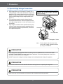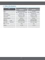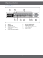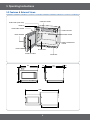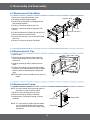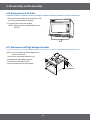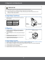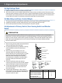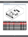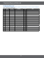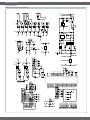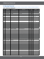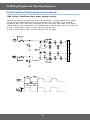
1
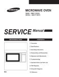
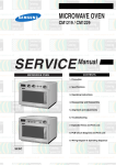
08/2011 Mod: CM1529 Production code: CM-1529A BASIC: CM1529 CM1529A MODEL: MODEL CODE: CM1529A Handle Door Design. 2. 0.9 cu.ft Cavity 3. High Power Output P 1 2 3 4 5 6 7 8 9 + 20sec 0 • Contents 1. Precaution. . . . . . . . . . . . . . . . . . . . . . . . . . . . . . . . . . . . . . . . . . . . . . . . . . . . . . . . . . . . . . . . . . . . . . . . . . . . . . . . . . . . . . . . . . . . 3 1-1 Safety precautions. . . . . . . . . . . . . . . . . . . . . . . . . . . . . . . . . . . . . . . . . . . . . . . . . . . . . . . . . . . . . . . . . . . . . . . . . . . . . . . . . . . 4 1-2 Special High Voltage Precautions. . . . . . . . . . . . . . . . . . . . . . . . . . . . . . . . . . . . . . . . . . . . . . . . . . . . . . . . . . . . . . . . . . . . . . . 5 2. Specifications . . . . . . . . . . . . . . . . . . . . . . . . . . . . . . . . . . . . . . . . . . . . . . . . . . . . . . . . . . . . . . . . . . . . . . . . . . . . . . . . . . . . . . . . . 6 2-1 Table of Specifications. . . . . . . . . . . . . . . . . . . . . . . . . . . . . . . . . . . . . . . . . . . . . . . . . . . . . . . . . . . . . . . . . . . . . . . . . . . . . . . . 6 3. Operating Instructions. . . . . . . . . . . . . . . . . . . . . . . . . . . . . . . . . . . . . . . . . . . . . . . . . . . . . . . . . . . . . . . . . . . . . . . . . . . . . . . . . . 7 3-1 Control Panel. . . . . . . . . . . . . . . . . . . . . . . . . . . . . . . . . . . . . . . . . . . . . . . . . . . . . . . . . . . . . . . . . . . . . . . . . . . . . . . . . . . . . . . 7 3-2 Features & External Views . . . . . . . . . . . . . . . . . . . . . . . . . . . . . . . . . . . . . . . . . . . . . . . . . . . . . . . . . . . . . . . . . . . . . . . . . . . . 8 4. Disassembly and Reassembly. . . . . . . . . . . . . . . . . . . . . . . . . . . . . . . . . . . . . . . . . . . . . . . . . . . . . . . . . . . . . . . . . . . . . . . . . . . . 9 4-1 Replacement of Magnetron, Motor Assembly and Lamp . . . . . . . . . . . . . . . . . . . . . . . . . . . . . . . . . . . . . . . . . . . . . . . . . . . . . 9 4-2 Replacement of High Voltage Transfomer. . . . . . . . . . . . . . . . . . . . . . . . . . . . . . . . . . . . . . . . . . . . . . . . . . . . . . . . . . . . . . . . . 9 4-3 Replacement of Door Assembly . . . . . . . . . . . . . . . . . . . . . . . . . . . . . . . . . . . . . . . . . . . . . . . . . . . . . . . . . . . . . . . . . . . . . . . 10 4-3-1 Removal of Door Assembly. . . . . . . . . . . . . . . . . . . . . . . . . . . . . . . . . . . . . . . . . . . . . . . . . . . . . . . . . . . . . . . . . . . . . . 10 4-3-2 Removal of Door Handle. . . . . . . . . . . . . . . . . . . . . . . . . . . . . . . . . . . . . . . . . . . . . . . . . . . . . . . . . . . . . . . . . . . . . . . . 10 4-3-3 Reassembly Test. . . . . . . . . . . . . . . . . . . . . . . . . . . . . . . . . . . . . . . . . . . . . . . . . . . . . . . . . . . . . . . . . . . . . . . . . . . . . . 10 4-4 Replacement of Fuse and H.V Fuse. . . . . . . . . . . . . . . . . . . . . . . . . . . . . . . . . . . . . . . . . . . . . . . . . . . . . . . . . . . . . . . . . . . . . 11 4-5 Replacement of Drive Motor & Assy Stirrer. . . . . . . . . . . . . . . . . . . . . . . . . . . . . . . . . . . . . . . . . . . . . . . . . . . . . . . . . . . . . . . . 11 4-5-1 Replacement of Drive Motor . . . . . . . . . . . . . . . . . . . . . . . . . . . . . . . . . . . . . . . . . . . . . . . . . . . . . . . . . . . . . . . . . . . . . . 11 4-5-2 Replacement of Ass’y Stirrer. . . . . . . . . . . . . . . . . . . . . . . . . . . . . . . . . . . . . . . . . . . . . . . . . . . . . . . . . . . . . . . . . . . . . . 11 4-6 Replacement of Control Circuit Box Assy and P.C.Board. . . . . . . . . . . . . . . . . . . . . . . . . . . . . . . . . . . . . . . . . . . . . . . . . . . . 12 4-6-1 Removal of Control Box Assembly. . . . . . . . . . . . . . . . . . . . . . . . . . . . . . . . . . . . . . . . . . . . . . . . . . . . . . . . . . . . . . . . . 12 4-6-2 Removal of main P.C.Board. . . . . . . . . . . . . . . . . . . . . . . . . . . . . . . . . . . . . . . . . . . . . . . . . . . . . . . . . . . . . . . . . . . . . . 12 4-7 Replacement of Fan Motor. . . . . . . . . . . . . . . . . . . . . . . . . . . . . . . . . . . . . . . . . . . . . . . . . . . . . . . . . . . . . . . . . . . . . . . . . . . 13 4-8 Replacement of Tray. . . . . . . . . . . . . . . . . . . . . . . . . . . . . . . . . . . . . . . . . . . . . . . . . . . . . . . . . . . . . . . . . . . . . . . . . . . . . . . . 13 4-9 Replacement of Lamp . . . . . . . . . . . . . . . . . . . . . . . . . . . . . . . . . . . . . . . . . . . . . . . . . . . . . . . . . . . . . . . . . . . . . . . . . . . . . . . . . . . 13 4-10 Replacement of Air Filter. . . . . . . . . . . . . . . . . . . . . . . . . . . . . . . . . . . . . . . . . . . . . . . . . . . . . . . . . . . . . . . . . . . . . . . . . . . . 14 4-11 Replacement of High Voltage Capacitor. . . . . . . . . . . . . . . . . . . . . . . . . . . . . . . . . . . . . . . . . . . . . . . . . . . . . . . . . . . . . . . . 14 5. Alignment and Adjustments. . . . . . . . . . . . . . . . . . . . . . . . . . . . . . . . . . . . . . . . . . . . . . . . . . . . . . . . . . . . . . . . . . . . . . . . . . . . . 15 5-1 High Voltage Transformer. . . . . . . . . . . . . . . . . . . . . . . . . . . . . . . . . . . . . . . . . . . . . . . . . . . . . . . . . . . . . . . . . . . . . . . . . . . . 15 5-2 Magnetron. . . . . . . . . . . . . . . . . . . . . . . . . . . . . . . . . . . . . . . . . . . . . . . . . . . . . . . . . . . . . . . . . . . . . . . . . . . . . . . . . . . . . . . . 15 5-3 High Voltage Capacitor. . . . . . . . . . . . . . . . . . . . . . . . . . . . . . . . . . . . . . . . . . . . . . . . . . . . . . . . . . . . . . . . . . . . . . . . . . . . . . 15 5-4 High Voltage Diode. . . . . . . . . . . . . . . . . . . . . . . . . . . . . . . . . . . . . . . . . . . . . . . . . . . . . . . . . . . . . . . . . . . . . . . . . . . . . . . . . 16 5-5 Main Relay and Power Control RelayA. . . . . . . . . . . . . . . . . . . . . . . . . . . . . . . . . . . . . . . . . . . . . . . . . . . . . . . . . . . . . . . . . . 16 5-6 Adjustment of Primary Switch, Door Sensing Switch and Monitor Switch. . . . . . . . . . . . . . . . . . . . . . . . . . . . . . . . . . . . . . . . 16 5-7 Output Power of Magnetron . . . . . . . . . . . . . . . . . . . . . . . . . . . . . . . . . . . . . . . . . . . . . . . . . . . . . . . . . . . . . . . . . . . . . . . . . . 17 5-8 Microwave Heat Distribution - Heat Evenness . . . . . . . . . . . . . . . . . . . . . . . . . . . . . . . . . . . . . . . . . . . . . . . . . . . . . . . . . . . . 17 5-9 Procedure for Measurement of Microwave Energy Leakage . . . . . . . . . . . . . . . . . . . . . . . . . . . . . . . . . . . . . . . . . . . . . . . . . 18 5-10 Note on Measurement. . . . . . . . . . . . . . . . . . . . . . . . . . . . . . . . . . . . . . . . . . . . . . . . . . . . . . . . . . . . . . . . . . . . . . . . . . . . . . 18 5-11 Record keeping and notification after measurement. . . . . . . . . . . . . . . . . . . . . . . . . . . . . . . . . . . . . . . . . . . . . . . . . . . . . . . 18 6. Troubleshooting . . . . . . . . . . . . . . . . . . . . . . . . . . . . . . . . . . . . . . . . . . . . . . . . . . . . . . . . . . . . . . . . . . . . . . . . . . . . . . . . . . . . . . 19 6-1 Electrical Malfunction . . . . . . . . . . . . . . . . . . . . . . . . . . . . . . . . . . . . . . . . . . . . . . . . . . . . . . . . . . . . . . . . . . . . . . . . . . . . . . . 19 6-2 Error Codes & Corrections . . . . . . . . . . . . . . . . . . . . . . . . . . . . . . . . . . . . . . . . . . . . . . . . . . . . . . . . . . . . . . . . . . . . . . . . . . . 21 7. Exploded Views and Parts List . . . . . . . . . . . . . . . . . . . . . . . . . . . . . . . . . . . . . . . . . . . . . . . . . . . . . . . . . . . . . . . . . . . . . . . . . . 22 7-1 Exploded Views. . . . . . . . . . . . . . . . . . . . . . . . . . . . . . . . . . . . . . . . . . . . . . . . . . . . . . . . . . . . . . . . . . . . . . . . . . . . . . . . . . . . 22 7-2 Main Parts List. . . . . . . . . . . . . . . . . . . . . . . . . . . . . . . . . . . . . . . . . . . . . . . . . . . . . . . . . . . . . . . . . . . . . . . . . . . . . . . . . . . . . 23 7-3 Door Parts List. . . . . . . . . . . . . . . . . . . . . . . . . . . . . . . . . . . . . . . . . . . . . . . . . . . . . . . . . . . . . . . . . . . . . . . . . . . . . . . . . . . . . 25 7-4 Control Parts List. . . . . . . . . . . . . . . . . . . . . . . . . . . . . . . . . . . . . . . . . . . . . . . . . . . . . . . . . . . . . . . . . . . . . . . . . . . . . . . . . . . 26 7-5 Standard Parts List. . . . . . . . . . . . . . . . . . . . . . . . . . . . . . . . . . . . . . . . . . . . . . . . . . . . . . . . . . . . . . . . . . . . . . . . . . . . . . . . . 27 8. Schematic Diagrams. . . . . . . . . . . . . . . . . . . . . . . . . . . . . . . . . . . . . . . . . . . . . . . . . . . . . . . . . . . . . . . . . . . . . . . . . . . . . . . . . . . 28 8-1 Schematic Diagrams. . . . . . . . . . . . . . . . . . . . . . . . . . . . . . . . . . . . . . . . . . . . . . . . . . . . . . . . . . . . . . . . . . . . . . . . . . . . . . . . 28 9. Electrical Parts List. . . . . . . . . . . . . . . . . . . . . . . . . . . . . . . . . . . . . . . . . . . . . . . . . . . . . . . . . . . . . . . . . . . . . . . . . . . . . . . . . . . . 29 9-1 Electrical Parts List. . . . . . . . . . . . . . . . . . . . . . . . . . . . . . . . . . . . . . . . . . . . . . . . . . . . . . . . . . . . . . . . . . . . . . . . . . . . . . . . . 29 10. Wiring Diagrams . . . . . . . . . . . . . . . . . . . . . . . . . . . . . . . . . . . . . . . . . . . . . . . . . . . . . . . . . . . . . . . . . . . . . . . . . . . . . . . . . . . . . 32 10-1 Wiring Diagrams. . . . . . . . . . . . . . . . . . . . . . . . . . . . . . . . . . . . . . . . . . . . . . . . . . . . . . . . . . . . . . . . . . . . . . . . . . . . . . . . . . 32 10-2 Description of Operating Sequence . . . . . . . . . . . . . . . . . . . . . . . . . . . . . . . . . . . . . . . . . . . . . . . . . . . . . . . . . . . . . . . . . . . 33 11. Reference. . . . . . . . . . . . . . . . . . . . . . . . . . . . . . . . . . . . . . . . . . . . . . . . . . . . . . . . . . . . . . . . . . . . . . . . . . . . . . . . . . . . . . . . . . . 36 11-1 Model name standard. . . . . . . . . . . . . . . . . . . . . . . . . . . . . . . . . . . . . . . . . . . . . . . . . . . . . . . . . . . . . . . . . . . . . . . . . . . . . . 36 11-2 Customer inquiry cases and countermeasures. . . . . . . . . . . . . . . . . . . . . . . . . . . . . . . . . . . . . . . . . . . . . . . . . . . . . . . . . . . 38 2 1. Precaution 3 1. Precaution Follow these special safety precautions. Although the microwave oven is completely safe during ordinary use, repair work can be extremely hazardous due to possible exposure to microwave radiation, as well as potentially lethal high voltages and currents. 1-1 Safety precautions ( ) 13. Design Alteration Warning: Use exact replacement parts only, i.e.,only those that are specified in thedrawings and parts lists of this manual. This is especially important for the Interlock switches, described above. Never alter or add to the mechanical or electrical design of the MWO. Any design changes or additions will void the manufacturer’s warranty. Always unplug the unit’s AC power cord from the AC power source before attempting to remove or reinstall any component or assembly. 14. Never defeat any of the B+ voltage interlocks. Do not apply AC power to the unit (or any of its assemblies) unless all solid-state heat sinks are correctly installed. 15. Some semiconductor (“solid state”) devices are easily damaged by static electricity. Such components are called Electrostatically Sensitive Devices (ESDs). Examples include integrated circuits and field-effect transistors. Immediately before handling any semiconductor components or assemblies, drain the electrostatic charge from your body by touching a known earth ground. 16. Always connect a test instrument’s ground lead to the instrument chassis ground before connecting the positive lead; always remove the instrument’s ground lead last. 17. When checking the continuity of the witches or transformer, always make sure that the power is OFF, and one of the lead wires is disconnected. 18. Components that are critical for safety are indicated in the circuit diagram by shading, or . 19. Use replacement components that have the same ratings, especially for flame resistance and dielectric strength specifications. A replacement part that does not have the same safety characteristics as the original might create shock, fire or other hazards. NOTE : Connect the oven to a 20A. When connecting the oven to a 15A,make sure that circuit breaker can operate. 1. All repairs should be done in accordance with the procedures described in this manual. This product complies with Federal Performance Standard 21 CFR 2. Microwave emission check should be performed to prior to servicing if the oven is operative. 3. If the oven operates with the door open :Instruct the user not to operate the oven and contact the manufacturer and the center for devices and radiological health immediately. 4. Notify the Central Service Center if the microwave leakage exceeds 5 mW/cm2. 5. Check all grounds. 6. Do not power the MWO from a “2-prong” AC cord. Be sure that all of the built-in protective devices are replaced. Restore any missing protective shields. 7. When reinstalling the chassis and its assemblies, be sure to restore all protective devices, including: nonmetallic control knobs and compartment covers. 8. Make sure that there are no cabinet openings through which people --particularly children--might insert objects and contact dangerous voltages. Examples: Lamp hole,ventilation slots. 9. Inform the manufacturer of any oven foundto have emission in excess of 5 mW/cm2 ,Make repairs to bring the unit into compliance at no cost to owner and try to determine cause. Instruct owner not to use oven until it has been brought into compliance. CENTRAL SERVICE CENTER 10. Service technicians should remove their watches while repairing an MWO. 11. To avoid any possible radiation hazard,replace parts in accordance with the wiring diagram. Also, use only the exact replacements for the following parts: Primary and secondary interlock switches, interlock monitor switch. 12. If the fuse is blown by the Interlock Monitor Switch: Replace all of the following at the same time: Primary, door sensing switch and power relay, as well as the Interlock Monitor Switch. The correct adjustment of these switches is described elsewhere in this manual. Make sure that the fuse has the correct rating for the particular model being repaired. 4 1. Precaution 1-2 Special High Voltage Precautions 1. High Voltage Warning Do not attempt to measure any of the high voltages --this includes the filament voltage of the magnetron. High voltage is present during any cook cycle. Before touching any components or wiring, always unplug the oven and discharge the high voltage capacitor (See Figure 1-1) 2. The high-voltage capacitor remains charged about 30 seconds after disconnection. Short the negative terminal of the high-voltage capacitor to to the oven chassis. (Use a screwdriver.) 3. High voltage is maintained within specified limits by closetolerance, safety-related components and adjustments. If the high voltage exceeds the specified limits, check each of the special components. Discharge the 2 High Voltage Capacitors before servicing! Screwdriver H.V.Capacitors Negative Terminal Note : Touch chassis side first then short to the high voltage capacitor terminal by using a screwdriver. PRECAUTION There exists HIGH VOLTAGE ELECTRICITY with high current capabilities in the circuits of the HIGH VOLTAGE TRANSFORMER secondary and filament terminals. It is extremely dangerous to work on or near these circuits with the oven energized. DO NOT measure the voltage in the high voltage circuit including filament voltage of magnetron. PRECAUTION Servicemen should remove their watches whenever working close to or replacing the magnetron. PRECAUTION Never touch any circuit wiring with your hand nor with uninsulated tool during operation. 5 2-1 Table of Specifications Items Model Model Basic Model New Model CM1929, CM1919/ELE Timer Max. 25min (Power Level : HIGH) Max. 25min (Power Level : HIGH) 230V 50Hz, AC 240V 50Hz, AC Microwave : 3200W Microwave : 3000W 1850W (IEC-705) 15000W (IEC-705) 2450MHz 2450MHz OM75P(20)ESS OM75P(20)ESGN Outside 464 x 368 x 557mm 464 x 368 x 557mm Oven Cavity 370 x 190 x 370mm 370 x 190 x 370mm 32Kg 32Kg Power Source Power Consumption Output Power Operating Frequency Magnetron Dimensions (W x H x D) Net Shipping 34,5 Kg . 6 CM1529A 34,5 Kg . 3. Operating Instructions 3-1 Control Panel 1 2 P 4 1 2 3 4 5 6 7 8 9 0 + 20sec 3 1. 2. 3. 4. 5. 5 6 7 6. 7. 8. 9. 10. DISPLAY PROGRAM PAD PROGRAM LOCK PAD NUMBER PADS(Time, Memory Programming) POWER LEVEL SELECTOR PAD 7 8 9 10 DEFROST SELECTOR PAD DOUBLE QUANTITY PAD +20sec PAD (One Touch Cook Pad) STOP/CANCEL PAD START BUTTON 3. Operating Instructions 3-2 Features & External Views CONTROL PANEL OVEN LAMP (230V 25W) DISPLAY OVEN LAMP COVER START BUTTON CEILING COVER DOOR HANDLE SAFETY INTERLOCK HOLES DOOR PLATE TRAY DOOR LATCHES AIR FILTER 557 530 43 368 464 10 444 486 1000 514 8 26 4. Disassembly and Reassembly 4-1 Replacement of Magnetron, Motor Assembly and Lamp Remove the magnetron including the shield case, permanent magnet, choke coils and capacitor (all of which are contained in one assembly). Duct-MGT-L Nut-Flange 1. Remove the outer panel. NOTE: B efore servicing, make sure to discharge electric charge remaining on the high voltage capacitors or wait for more than 5 min. 2. Remove the back cover. 3. Disconnect all lead wires from the magnetron. 4. Remove screws securing the duct-MGT and duct-fan. 5. Remove the nut-flanges securing the magnetron by using a box wrench. 6. Take out the magnetron very carefully. NOTE1: W hen removing the magnetron, make sure that its antenna does not hit any adjacent parts, or it may be damaged. NOTE2: W hen replacing the magnetron, be sure to remount the magnetron gasket in the correct position and make sure the gasket is in good condition. (See page 19 for adjustment instructions.) Duct-Fan DuctMGT-R Magnetron 4-2 Replacement of High Voltage Transfomer 1. Discharge the high voltage capacitor. 2. Disconnect all the leads. 3. Remove the mounting bolts. 4. Reconnect the leads correctly and firmly. H. V. Trans 4 Mounting Bolts 9 4. Disassembly and Reassembly 4-3 Replacement of Door Assembly 4-3-1 Removal of Door Assembly NOTE: Be sure to wear gloves when you disassemble or assemble the parts. 1. Remove hex bolts securing the upper hinge and lower hinge. Then remove the door assembly. 2. Insert the flat screwdriver or thin metal plate into the gap between the door E and door C to remove Door C from the door assembly. 3. Remove 2 screws securing the Door Handle. 4. Unbend the 6 metal tabs around the trim of Decoration Door Cover. 5. Remove 3 screws securing the Door E Assay. 6. Remove upper hinge and lower hinge. 7. Remove Decoration Door, Screen B, Key-Door, Spring-Key, Pin-Key as needed. 4-3-2 Removal of Door Handle 1. Remove hex bolts securing the upper hinge and lower hinge. Then remove the door assembly. 2. Insert the flat screwdriver or thin metal plate into the gap between the door E and door C to remove Door C from the door assembly. NOTE: Be careful when handling Door C as is fragile. NOTE: The thickness of the flat screwdriver or thin metal plate inserted into the gap should be 0.5mm or less. 3. Remove 2 screws securing the Door Handle to the Door E Assy. 4. Unbend the 2 metal tabs at both ends of the Door Handle to remove the Door Handle Cover from the Door Handle. Door C Upper Hinge Door E Ass'y Decoration Door Screen B Decoration Door Cover 2 screws securing Door Handle Lower Hinge Spring-Key #- 4 Door Handle Cover Key-Door Pin-Key W ATT S Door Handle 4-3-3 Reassembly Test After replacement of the defective component parts of the door, reassemble it and follow the instructions below for proper installation and adjustment so as to prevent an excessive microwave leakage. 1. When mounting the door to the oven, be sure to adjust the door parallel to the bottom line of the oven face plate by moving the upper hinge and lower hinge in the direction necessary for proper alignment. 2. Adjust so that the door has no play between the inner door surface and oven front surface. If the door assembly is not mounted properly, microwave energy may leak from the space between the door and oven. 3. Do the microwave leakage test. 10 4. Disassembly and Reassembly 4-4 Replacement of Fuse and H.V Fuse 1. Disconnect the oven from the power source. 2. Remove defective fuse from Noise filter. 3. When replacing the fuse, be sure to use an exact replacement part. If new fuse blows out again after replacement, check the primary interlock switch, door sensing switch and interlock monitor switch. 4. When the above three switches operate properly, check if any other part such as the control circuit board, fan motor or high voltage transformer is defective. 10A Fuse H.V.Fuse 4-5 Replacement of Drive Motor & Assy Stirrer 4-5-1 Replacement of Drive Motor 1. Remove a screw securing the drive motor 2. Open the door. 3. Hold side syoppers of ceiling cover (Ass’y Stirrer Cover) with both hands and pull them in and down. 4. Take the celing cover out of the oven cavity. 5. Remove plastic clips securing the Ass’y Stirrer. Caution: W hen removing the Ass’y Stirrer Cover,be sure to be extremely careful about the exposed inside components on the top of the oven cavity. If any of them are deformed, abnormal symptom can happen such as arcing or sparks during operation. To remove Ass'y Stirrer Cover: Hold side stoppers of ceiling cover with both hands and pull them in and down. 4-5-2 Replacement of Ass’y Stirrer Screw Drive Motor 1. Remove outer panel and back-cover. 2. Disconnect all the lead wires from the drive motor. 3. Remove a screw securing the drive motor. 4. When replacing the drive motor, be sure to remount it in the correct position with the coupler. 5. Connect all the leads to the drive motor. 6. Screw the drive motor to the bracket motor with a screw driver Ass’y Stirrer Ass’y Stirrer Cover 11 Plastic Clips 4. Disassembly and Reassembly 4-6 Replacement of Control Circuit Box Assy and P.C.Board 4-6-1 Removal of Control Box Assembly 1. Be sure to discharge any static electric charge built up on your body and avoid touching the touch control circuitry. 2. Remove 3 screws securing the Control Box Ass’y to the oven cavity. 3. Disconnect all the lead wires, connectors and ground taping from the main control circuit board (PCB1). 4. Lift up the FPC connector hooks about 5mm upward which connects to the main control circuit board (PCB1) from the tail of switch membrane of the control box assembly. 5. Remove a screw securing the tapped taping to PCB1. 6. Remove Control Box Ass’y. 7. To replace Digitron, remove 2 screws securing the PCB 4. 8. To replace Start Button Circuitry, remove 2 screws securing the PCB3. 9. Unbend the metal tabs holding the Panel -Base to Control Box body. 4-6-2 Removal of main P.C.Board 1. Remove Control Box Assembly by following the steps 1~ 5 at left. 2. Remove 4 screws securing the main P.C.Board to the bracket P.C.Board. NOTE: When handling the the touch control circuitry, be most careful to avoid damage. Main P.C.Board (PCB1) Wire Harness-C Digitron(PCB4) Wire Harness-B Panel Base Wire Harness-F Window-Display Cover Panel PCB3 Cover-Panel/L Switch-Membrane Control Box Assy Cover-Panel/R 12 4. Disassembly and Reassembly 4-7 Replacement of Fan Motor 1. Remove the outer panel and back-cover. 2. Discharge the high voltage capacitor. 3. Remove all the lead wires from Magnetron and High Voltage Capacitor. 4. Remove 2 screws securing the duct fan. 5. Remove 2 screws securing the Supporter-Fan Mount. 6. Lift the Fan Motor Ass’y slightly left and pull it out. 7. Remove lead wires and connectors. 8. Turn the fan motor Ass’y over so that the bracket side is up. 9. Remove 2 screws securing the Fan Motor. Ventilation Motor C-Film Supporter-Fan-Mount Duct-Fan 4-8 Replacement of Tray 1. Open the door. 2. Remove the tray by inserting a thin metal tool into the gap between the oven wall and the tray siliconcover. 3. Insert the new tray by tilting it across the oven cavity. 4. Firstly fix the front part (refers to the place where the silicon cover is thinner than the other 3 edges) and then place the backward part carefully and firmly. NOTE: Be careful when you handle the tray since it is fragile. Tray 4-9 Replacement of Lamp NOTE: You don’t need to remove the outer panel or other parts in order to replace a lamp. 1. Remove a screw securing the lamp cover. 2. Remove the lamp by rotating it clockwise. 3. Replace with a new lamp by rotating it counterclockwise. Lamp Cover NOTE : If it is necessary to replace the lamp holder, you can disconnect lead wires by pushing down on the hole of lead wires using a long pointed tool. Outer Panel 13 Lamp Holder 4. Disassembly and Reassembly 4-10 Replacement of Air Filter 1. Remove the bolt at both ends of the Air Filter. Then the locking clamps inside are released. 2. L ift the Air Filter off the post carefully. NOTE : S pacer pins are not detachable from the Air Filter Bolt 4-11 Replacement of High Voltage Capacitor NOTE: It is not necessary to remove Magnetron in order to remove HVC. 1. Remove the outer panel and back cover. 2. Discharge the high voltage capacitor. 3. Remove HVT wire and H.V.Fuse. 4. Remove screws securing HVC bracket. H.V.Capacitor 14 5. Alignment and Adjustments PRECAUTION 1. High voltage is present at the high voltage terminals during any cook cycle. 2. It is neither necessary nor advisable to attempt measurement of the high voltage. 3. Before touching any oven components or wiring, always unplug the oven from its power source and discharge the high voltage capacitor. 5-1 High Voltage Transformer 1. Remove connectors from the transformer terminals and check continuity. 2. Normal resistance readings are as follows: Terminal Resistance Secondary Approx. 98 Ω Filament Approx. 0 Ω Primary Approx. 1.3 Ω Primary Terminals Secondary Terminal (Room temperature = 20°C) 5-2 Magnetron 1. Continuity checks can indicate only an open filament or a shorted magnetron. To diagnose an open filament or shorted magnetron. 2. Isolate the magnetron from the circuit by disconnecting its leads. 3. A continuity check across the magnetron filament terminals should indicate one ohm or less. 4. A continuity check between each filament terminal and magnetron case should read open. Magnetron Antenna Gasket Plate Cooling Fins 5-3 High Voltage Capacitor 1. 2. 3. 4. 5. Check continuity of the capacitor with the meter set at the highest resistance scale. Once the capacitor is charged, a normal capacitor shows continuity for a short time, and then indicates 9MΩ. A shorted capacitor will show continuous continuity. An open capacitor will show constant 9MΩ. Resistance between each terminal and chassis should read infinite. 15 5. Alignment and Adjustments 5-4 High Voltage Diode 1. Isolate the diode from the circuit by disconnecting its leads. 2. With the ohm-meter set at the highest resistance scale, measure across the diode terminals. Reverse the meter leads and read the resistance. A meter with 6V, 9V or higher voltage batteries should be used to check the front-to back resistance of the diode (otherwise an infinite resistance may be read in both directions). The resistance of a normal diode will be infinite in one direction and several hundred KΩ in the other direction. 5-5 Main Relay and Power Control RelayA 1. The relays are located on the PCB Ass’y. Isolate them from the main circuit by disconnecting the leads. 2. Operate the microwave oven with a water load in the oven. Set the power level set to high. 3. Check continuity between terminals of the relays after the start pad is pressed. 5-6 Adjustment of Primary Switch, Door Sensing Switch and Monitor Switch PRECAUTION For continued protection against radiation hazard, replace parts in accordance with the wiring diagram and be sure to use the correct part number for the following switches: Primary and secondary interlock switches, and the interlock monitor switch (replace all together). Then follow the adjustment procedures below. After repair and adjustment, be sure to check the continuity of all interlock switches and the interlock monitor switch. 1. When mounting Primary switch and Interlock Monitor switch to Latch Body, consult the figure. 2. No specific adjustment during installation of Primary switch and Monitor switch to the latch body is necessary. 3. When mounting the Latch Body to the oven assembly, adjust the Latch Body by moving it so that the oven door will not have any play in it. Check for play in the door by pulling the door assembly. Make sure that the latch keys move smoothly after adjustment is completed. Completely tighten the screws holding the Latch Body to the oven assembly. 4. Reconnect to Monitor switch and check the continuity of the monitor circuit and all latch switches again by following the components test procedures. 5. Confirm that the gap between the switch housing and the switch actuator is no more than 0.5mm when door is closed. 6. Interlock Switch Replacement - When replacing faulty switches, be sure switch mounting tabs are not bent, broken or otherwise deficient in their ability to secure the switches in place. Latch-Body Door Sensing S/W Lever-Switch/U Interlock Monitor S/W Primary S/W Lever-Switch/L Primary S/W Interlock Monitor S/W NC COM NO WHT BRN COM COM NO BRN/ORG BLU COM NO WHT 16 RED/YEL PINK/PINK COM NC RED/WHT NO BRN BRN/AZR Primary Interlock switch Monitor switch(COM-NC) Monitor switch(COM-NO) Door Sensing S/W (Secondary Interlock S/W) Door Sensing S/W NO ORG ORG Door Open Door Closed 0 ∞ ∞ 0 0 ∞ 0 ∞ 5. Alignment and Adjustments 5-7 Output Power of Magnetron PRECAUTION MICROWAVE RADIATION PERSONNEL SHOULD NOT ALLOW EXPOSURE TO MICROWAVE RADIATION FROM MICROWAVE GENERATOR OR OTHER PARTS CONDUCTING MICROWAVE ENERGY. The output power of the magnetron can be measured by performing a water temperature rise test. Equipment needed : • Two 1-liter cylindrical borosilicate glass vessel (Outside diameter 190 mm) • One glass thermometer with mercury column NOTE: Check line voltage under load. Low voltage will lower the magnetron output. Make all temperature and time tests with accurate equipment. 1. Fill the one liter glass vessel with water. 2. Stir water in glass vessel with thermometer, and record glass vessel’s temperature (“T1”, 10±1°C). 3. After moving the water into another glass vessel, place it in the center of the cooking tray. Set the oven to high power and operate for 25 seconds exactly. (3 seconds included as a holding time of magnetron oscillation:) 4. When heating is finished, stir the water again with the thermometer and measure the temperature (“T2”). 5. Subtract T1 from T2. This will give you the water temperature rise. (∆T) 6. The output power is obtained by the following formula; Output Power = 4.187 x 1000 x ∆T+0.55xMcx(T2 -T1) 22 : Heating Time (sec) 4.187 : Coefficient for Water 22 1000 : Water (cc) ∆T : Temperature Rise (T2-T1) To : Room Temperature Mc : Cylindrical borosilicate glass weight 7. Normal temperature rise for this model is 7°C to 10°C at ‘HIGH’. NOTE 1: Variations or errors in the test procedure will cause a variance in the temperature rise. Additional power test should be made if temperature rise is marginal. NOTE 2: Output power in watts is computed by multiplying the temperature rise (step 5) by a factor of 91 times the of centigrade temperature. 5-8 Microwave Heat Distribution - Heat Evenness The microwave heat distribution can be checked indirectly by measuring the water temperature rise at certain positions in the oven: 1. Prepare five beakers made of ‘Pyrex’, having 100 milliliters capacity each. 2. Measure exactly 100milliliters off water load with a measuring cylinder, and pour into each beaker. 3. Measure the temperature of each water load. (Readings shall be taken to the first place of decimals.) 4. Put each beaker in place on the cooking tray as illustrated in figure below. Start heating. D 5. After heating for 2 minutes, measure the water temperature in each beaker. Beaker D 6. Microwave heat distribution rate can be calculated as follows: Heat Distribution = Minimum Temperature Rise Minimum Temperature Rise The result should exceed 65% X 100(%) D/4 17 D/4 D/4 D/4 Cooking Tray 5. Alignment and Adjustments 5-9 Procedure for Measurement of Microwave Energy Leakage 1. Pour 275±15cc of 20±5°C(68±9°F) water in a beaker which is graduated to 600cc, and place the beaker in the center of the oven. 2. Start to operate the oven and measure the leakage by using a microwave energy survey meter. 3. Set survey meter with dual ranges to 2,450MHz. 4. When measuring the leakage, always use the 2 inch spacer cone with the probe. Hold the probe perpendicular to the cabinet door. Place the spacer cone of the probe on the door and/or cabinet door seam and move along the seam, the door viewing window and the exhaust openings moving the probe in a clockwise direction at a rate of 1 inch/sec. If the leakage testing of the cabinet door seam is taken near a corner of the door, keep the probe perpendicular to the areas making sure that the probe end at the base of the cone does not get closer than 5cm to any metal. If it gets closer than 5cm, erroneous readings may result. 5. Measured leakage must be less than 4mW/cm2 , after repair or adjustment. Maximum allowable leakage is 5mW/cm2 . 4mW/cm2 is used to allow for measurement and meter accuracy 5-10 Note on Measurement 1. Do not exceed the limited scale. 2. The test probe must be held on the grip of the handle, otherwise a false reading may result when the operator’s handle and the probe. 3. When high leakage is suspected, do not move the probe horizontally along the oven surface; this may cause damage to the probe 4. Follow the recommendation of manufacturer of the microwave energy survey meter. Probe Spacer Cone 5-11 Record keeping and notification after measurement 1. After adjustment and repair of a radiation preventing device, make a repair record for the measured values, and keep the data. 2. If the radiation leakage is more than 4mW/cm2 after determining that all parts are in good condition, functioning properly and the identical parts are replaced as listed in this manual notify that fact to ; CENTRAL SERVICE CENTER 3. At least once a year have the microwave energy survey meter checked for accuracy by its manufacturer 18 6. Troubleshooting PRECAUTION 1. 2. 3. 4. CHECK GROUNDING BEFORE CHECKING FOR TROUBLE. BE CAREFUL OF THE HIGH VOLTAGE CIRCUIT. DISCHARGE THE HIGH VOLTAGE CAPACITOR. WHEN CHECKING THE CONTINUITY OF THE SWITCHES OR TRANSFORMER, DISCONNECT ONE LEAD WIRE FROM THESE PARTS AND THEN CHECK CONTINUITY WITHOUT THE POWER SOURCE ON. TO DO OTHERWISE MAY RESULT IN A FALSE READING OR DAMAGE TO YOUR METER. 5. DO NOT TOUCH ANY PART OF THE CIRCUIT OR THE CONTROL CIRCUIT BOARD, SINCE STATIC DISCHARGE MAY DAMAGE IT. ALWAYS TOUCH GROUND WHILE WORKING ON IT TO DISCHARGE ANY STATIC CHARGE BUILT UP. 6-1 Electrical Malfunction SYMPTOM Oven is dead. Fuse is OK. No display and no operation at all. No display and no operation at all. Fuse is blown. Oven does not accept key input (Program) Timer starts countdown but no microwave oscillation. (No heat while oven lamp and fan motor turn on.) CAUSE 1. Open or loose lead wire harness 2. Open thermal cutout (Magnetron) 3. Defective Ass’y PCB CORRECTIONS Check fan motor when thermal cutout is defective. Check adjustment of primary, 1. Shorted lead wire harness 2. Defective primary latch switch (NOTE 1) interlock monitor, power relay, door sensing switch. 3. Defective monitor switch (NOTE1) 4. Shorted H.V.Capacitor 5. Shorted H.V.Transformer (NOTE2) NOTE 1 : All of these switches must be replaced at the same time.(refer to adjustment instructions) Check continuity of power relay contacts and if it has continuity, replace power relay also. NOTE 2 : When H.V.Transformer is replaced, check diode and magnetron also. Refer to operation procedure. 1. Key input is not in-Sequence 2. Open or loose connection of membrane key pad to Ass’y PCB 3. Shorted or open membrane panel 4. Defective Ass’y PCB Replace PCB main. 1. Open or loose connection of high voltage circuit especially magnetron filament circuit NOTE : L arge contact resistance will bring lower magnetron filament voltage and cause magnetron to lower output and/or intermittent oscillation. 2. Defective high voltage components H.V.Transformer H.V. Capacitor H.V.Diode, H.V.Fuse Magnetron 19 Adjust door and latch switches. Check high voltage component according to component test procedure and replace if it is defective. 6. Troubleshooting SYMPTOM Oven lamp goes off Microwave output is low;. Oven takes longer time to cook food. (Noheat while oven lamp and ventilation) CAUSE 1. Loose lead wire or open filament 2. Misadjustment of latch switch 3. Defactive primary latch switch 1. Decrease in power source voltage. 2. Open or loose wiring of magnetron filament circuit. (Intermittent oscillation)) 3. Aging of magnetron 4. Defective high voltage compnents H.V. Transfomer H.V. Capacitor H.V. Diode, H.V. Fuse Magnetron Defective Ass’y PCB Oven does not operate and return to the plugged in mode. Loud buzzing noise can be 1. Loose fan and fan motor heard. 2. Loose screws on H.V.Transformer 3. Shorted H.V.Diode 4. Loose or missing screw on CoverBack Drive motor not work. 1. Open or loose wiring of turntable motor. (Ass’y stirrer dose not rotate.) 2. Defective turntable motor. 3. Defective ass’y stirrer Oven stops operation during 1.Operationofthermalcutout cooking (Magnetron or Cavity) 2. Fan motor does not rotate. Sparks 1. Metallic ware or cooking dishes touching on the oven wall. 2. Ceramic ware trimmed with gold or silver powder also causes sparks. Uneven cooking Noise from the turntable motor when it starts to operate. Oven can program but timer does not start. CORRECTIONS Tighten lamp lead wire or replace with a new lamp Consult electrician. Check high coltage component according to component test procedure and replace if defective Replace PCB main. Tighten screws of fan motor. Tighten screws of H.V.Transformer. Replace H.V.Diode. Tighten screws of Cover-Back Check the wire of drivemotor Replace drive motor. Replace ass’y stirrer. Adjust door and latch switches. Replace Fan motor. Informthecustomerofproperuse. Do not use any type of cookware with metallic trimming. Uneven intensity of microwave due to Wrap thinner parts of the food with its characteristics. aluminum foil. Use plastic wrap or cover with a lid. Stir once or twice while cooking foods such as soup, cocoa, or milk. Noise may result from the motor. Replace turntable motor. Defective circuitry of Start function of Main P.C.B Ass’y Loose lead wires. 20 Check circuitry of Start function of Main P.C.B Ass’y and replace if defective. Adjust od repair loose wires. 6. Troubleshooting 6-1 Electrical Malfunction (Continued) 21 6. Troubleshooting 6-1 Electrical Malfunction (Continued) 22 6. Troubleshooting 6-1 Electrical Malfunction (Continued) 23 6. Troubleshooting 6-2 Error Codes & Corrections CODE CAUSE CORRECTIONS E1 1. Improper input power freqency. 2. Defective Ass’y Main P.C.B Check if power frequency is 50Hz. Replace Ass’y Main P.C.B or MICOM E3 1. Overtheating inside cavity (no load or little load aging) 2. Air ventilation blocked around exhaust area 3. Ventilation motor failure and magnetron overheating Check if the oven was operating without load or too little load and plug the power cord in again. If error code ‘E3’ appears again in the window display, check resistance of Thermistor sensor and replace if defective. Check of any blocking mterials exhaust area around the Air Exhaust or ventilation opening and follow the instuctions above. Check if the ventilation motor is operative magnetron overheating and replace the motor if defective. E41 1. Main Relay (RY1) or Power Relay1(RY2) failure 2. Loose lead wires of relay 3. Primary or Monitor S/W failure 4. Loose lead wires of Primary or Monitor S/W 5. H.V.Trans input power sensing circuitry failure Check Main Relay (RY1), Power Relay1 (RY2) Primary S/W and Monitor S/W and replace if defective. Check if lead wires are loosened and connect firmly if loose. Check the circuitry and replace if defective. (Refer to Operating Sequence as shown in page 32.) E42 1. Main Relay (RY5) failure 2. Loose lead wires of Power relay (RY5) 3. Primary or Monitor S/W failure 4. Loose lead wires of Primary or Monitor S/W 5. Fuse(10A)blown out on neutral area of Ass’y Noise Filter. 6. H.V.Trans input power sensing circuitry failure Check Power Relay2,Primary S/W,Monitor S/W or Fuse and replace if defective. Check if lead wires are loosened and repair as necessary. 1. Memory IC(EEPROM IC) failure 2. MICOM failure Check Memory (IC3) and replace if defective. Replace Ass’y Main P.C.B or MICOM. E5 Check the circuitry.(Refer to Operating Sequence as shown in page 32.) 24 7. Exploded Views and Parts List 7-1 Exploded Views T108 T002 M102 M036 U003 R066 P047 M049 M066 M087 M078 P001 P075 P018 P017 M051 P019 M035 M029 P046 M020 B002 P048 B006 B018 Z016 M019 M017 M040 M112 M076 M041 Z781 M039 P069 B005 B012 B001 B001 B013 Z783 M024 W002 M042 M052 M155 M048 P061 M011 P074 M065 M129 M086 M001 M038 M015 25 7. Exploded Views and Parts List 7-2 Main Parts List (S.N.A : SERVICE NOT AVAILABLE) Level No. Code No. 1-1 M036 4713-000168 LAMP-INCANDESCENT 230V,-,25W,ORG,-,-,- 1 SA 1-1 Z783 6011-001140 BOLT-STUD M4,L8,NI PLT,BSW 1 SNA 1-1 M066 DE01-00095A FILM-LAMP 1 SA 1-1 M035 OM75P(20)ESGN 1 SA 1-1 M038 DE26-00058A TRANS H.V SHV-906EG1,230/240V,50HZ,2425V 1 SA 1-1 M049 DE31-10164B MOTOR SYNCHRONOUS M2CK34A709-H(B),120V60 1 SA 1-1 M029 DE47-20017A THERMOSTAT PW-2N(150/60,187Z),250V/7.5A, 1 SA 1-1 M102 DE47-40029A SOCKET-LAMP 250V2A,22.23,E14,BJB,-,-,- 1 SA 1-1 R066 DE61-50520A BRACKET-PCB -,SECC,T0.8,CM-1819,-,-,- 1 SA 1-1 M011 DE61-50541A BRACKET-EARTH -,SGCC2,T1.0,W15,L8,-,- 1 SNA 1-1 U003 DE61-90318A HOLDER-LAMP W134,SECC,-,W134,L40.5,-,L40 1 SA 1-1 M078 DE69-90054A CLIP-STIRRER 5MM,PFA,CM1819/29,-, 1 SNA 1-1 M001 DE70-30123A PANEL-OUTER -,STS430,T0.6,CM-1819,-,-,-, 1 SA 1-1 P046 DE72-50088A DUCT-FAN -,ALCOAT,T0.5,CM-1819,-,-,- 1 SA 1-1 P048 DE72-50089A DUCT-MGT/R -,SECC,T0.5,CM-1819,-,-,- 1 SA 1-1 P047 DE72-50090A DUCT-MGT/L CM-1819,SECC,T0.5,-,-,-,- 1 SA 1-1 M052 DE73-90027A FERRITE-CORE NI-ZN,T13.8,W21.0,L28.0,BNF 1 SNA 1-1 M020 DE91-50093T ASSY-MOTOR FAN -,240V,-,CM1919/1929,COMM 1 SA 1-2 M076 2301-001204 C-FILM,LEAD-PEF 1.50UF,-5TO+10%,450VAC,- 1 SA 1-2 M039 2501-001282 C-OIL 1.00UF,2100V(CLASS P),AL CAN T 1 SA 1-2 M024 DE31-10180A MOTOR VENTILATION SMV-1829EA,240V50HZ,22 1 SA 1-2 M040 DE61-00421A BRACKET-HVC CM1829,SECC,T0.8,-,-,-,- 1 SA 1-2 M112 DE61-30189A SUPPORT-FAN-MOUNT -,SECC,T1.0,CM-1819,-, 1 SA 1-2 M041 0402-001554 HVDIODE-RECTIFIER HV03-12T01,12000V,0.4A 1 SA 1-1 M042 DE91-70061A ASSY-H.V.FUSE THV060T-0800-H,5KV/0.80A,W 1 SA 1-1 P074 DE92-90514A ASSY-BACK COVER CM-1819,CM-1829,-,-,-,- 1 SA 1-1 P001 DE92-90515A ASSY-STIRRER CM-1819,CM-1829,-,-,-,- 1 SA 1-1 P061 DE92-90516B ASSY-BRACKET FILTER CM1819,-,-,-,-,- 1 SA 1-1 P017 DE92-90519A ASSY-DUCT AIR CM1819/29,-,-,CM1819/29,-, 1 SA 1-2 P018 DE47-20169A THERMOSTAT PW-2N(100/60,H,23.8,250V/7.5A 1 SA 1-2 P019 DE72-50091A DUCT-OVEN -,STS430,T0.4,CM-1819,-,-,- 1 SA 1-1 P075 DE97-00562A ASSY-COVER PANEL CM1829,-,-,-,-,- 1 SA 1-2 M087 COVER-STIRRER -,PP,CM-1819,-,-,-,-,- 1 SNA 1-2 M05 COVER-CEILING -,MICA_SHEET,T0 .5,W348,L31 1 SNA ASSY-FILTER COMM-BONN,NEW BKT SUPPORT,-, 1 SA 1-1 Description MAGNETRON Specification Q’ty -,PET,-,84,T0.15,114,CM-1819,,1KW/2460MHZ,3 .15V/4 SA/SNA Z016 DE92-90521D 1-2 P069 DE61-00723A BRACKET-SUPPORT CM1319,SECC/ALCOAT,T0.6, 1 SNA 1-2 M017 DE9600734A ASSY NOISE FILTER SN-1829,230V/50HZ,-,-, 1 SA 1-3 M019 3601-000448 FUSE-CARTRIDGE 250V,10A,SLOW-BLOW,CERAMI 1 SA 1-3 Z781 3601-001126 FUSE-CARTRIDGE 250V,1.6A,FAST-ACTING,CER 1 SA 1-1 M129 DE92-90533A ASSY-LAMP HOLDER CM1819/CM1829,-,-,-,-,- 1 SA 1-2 M065 DE63-90190B CUSHION-LAMP CM1819/29,PUT-FOAM,T7.0,W10 1 SNA 1-2 M086 DE71-60422A COVER-LAMP -,STS430,T0.6,CM-1819,-,-,-,- 1 SNA 1-1 M155 DE93-10106C ASSY BASE PLATE CM1819,SECC 1 SA 1-2 M048 DE80-10113C BASE-PLATE CM1819,SECC1,-,-,-,-,- 1 SNA 26 Remark H.V.T 7. Exploded Views and Parts List 7-2 Main Parts List(Continued) (S.N.A : SERVICE NOT AVAILABLE) Level No. Code No. Description 1-1 B018 DE93-20097E ASSY BODY LATCH 1-2 B002 3405-001032 SWITCH-MICRO 1-2 B001 3405-001034 1-2 B001 3405-001055 1-2 B005 1-2 B006 1-2 B012 Specification Q’ty SA/SNA CM1819/1829,EUROPE 1 SA 125/250VAC,16A,200GF,SPDT 1 SA SWITCH-MICRO 125/250VAC,16A,200GF,SPST-N 1 SA SWITCH-MICRO 125/250VAC,16A,200GF,SPST-N 1 SA DE61-00066A SPRING-Q CM1819/1829,MSWR,PI0.8,-,-,-,- 1 SA DE66-40062A LATCH-BODY -,-,-,-,-,-,- 1 SA DE66-90107A LEVER-SWITCH(U) PBT,CM-1819,-,-,-,-,- 1 SA 1-2 B013 DE66-90108A LEVER-SWITCH(L) PBT,CM-1819,-,-,-,-,- 1 SA 1-1 M015 DE96-00356G ASSY POWER CORD KKP-550A,-,250V15A,1700M 1 SA 1-1 W002 DE96-00503A ASSY-WIRE HARNESS A CM1929,230V 50HZ VI 1 SA 1-1 T002 DE97-00319A ASSY-TRAY CERAMIC CM1829,-,-,- 1 SA 1-2 T108 DE61-00170A FOOT-TRAY CM1049,URETHANE,-,WHT,-,-,- 1 SA 27 Remark 7. Exploded Views and Parts List 7-3 Door Parts List D006 D049 D004 D008 D021 D024 D022 D011 D008 D007 D018 D019 D026 (S.N.A : SERVICE NOT AVAILABLE) Level No. Code No. 1-1 D049 DE94-02846A Description ASSY DOOR Q’ty SA/SNA CM1529,STS,1500W Specification 1 SA 1-2 D018 DE60-60080A PIN-KEY A,M3.95,L21,STS304,-,CM-1819,- 1 SA 1-2 D007 DE61-70144A SPRING-KEY -,HSWR,PI1.0,-,OD6.5,L32.8,21 1 SA 1-2 D008 DE61-80138A HINGE -,SHV-945EG1,KEC,T3.0,W24.5,L2 1 SNA 1-2 D019 DE64-20123A HANDLE CM-1819,ZN-DICASTING,-,-,-,-,C 1 SA 1-2 D011 DE64-40296A DOOR-KEY -,CR3C,-,-,-,-,-,- 1 SA 1-2 D006 DE64-40298A DOOR-C -,PP,-,-,-,-,-,- 1 SA 1-2 D021 DE64-90145A DECORATION-DOOR -,ABS,CM-1819,-,-,-,CM-1 1 SA 1-2 D022 DE64-90146A DECORATION-COV/DOOR -,STS,CM-1819,-,-,-, 1 SA 1-2 D024 DE67-20174X SCREEN-DOOR(B) CM1929,GLASS,3.2,198.5,36 1 SA 1-2 D026 DE71-60433A COVER-HANDLE -,STS430,T0.5,CM-1819,-,-,- 1 SA 1-2 D004 DE92-50132B ASSY DOOR-E CM-1819,COATING,BLK 1 SA 28 Remark DOOR-E 7. Exploded Views and Parts List 7-4 Control Parts List # # # # # # # # # # (S.N.A : SERVICE NOT AVAILABLE) Level No. 1-1 C082 1-1 C082 1-2 1-3 Code No. Description Specification Q’ty SA/SNA ASSY CONTROL-BOX -,CM1529,-,COMMERCIAL 1 SA DE94-02182H ASSY CONTROL-BOX CM1529,230V50HZ,BLACK,STS,ABS,HEA VY-COMMERCIAL MWO,MEMBRANE 1 SA C001 DE93-30529N ASSY CONTROL-PANEL -,CM1329,-,COMMERCIAL 1 C004 DE34-00158C SWITCH MEMBRANE CM1529A1/XEU,COMMERCIAL,-, 1-3 C009 DE67-40161A WINDOW-DISPLAY -,RESIN-PMMA,82555,CM-181 1 SA 1-3 C020 DE70-30125A PANEL-BASE -,RESIN-ABS,TC,CM-1829,-,-,-, 1 SA 1-3 C021 DE71-60426A COVER-PANEL -,STS430,T0.5,TC,CM-1829,-,- 1 SA 1-3 C022 DE71-60428B COVER-PANEL(L/L) CM1019,ABS,-,-,-,-,-,CM 1 SA 1-3 C023 DE71-60429B COVER-PANEL(L/R) CM1019,ABS,-,-,-,-,-,CM 1 SA 1-3 C019 DE66-20212A BUTTON-START -,-,NI,CR-PLATING,-,-,CM-18 1 SA 1-2 C003 RCS-SMS2CM ASSY PCB PARTS CM1829 , 230V50HZ 1 SA 29 SA 1 Remark 0VER SA 7. Exploded Views and Parts List 7-5 Standard Parts List (S.N.A : SERVICE NOT AVAILABLE) Level Code No. 1-1 6002-000630 Description SCREW-TAPPING Specification PH,+,2S,M3,L8,ZPC(YEL),SWR Q’ty SA/ SNA 1 SA Remark MAIN PCB 1-1 6002-001325 SCREW-TAPPING TH,TORX,2S,M4,L12,ZPC(YEL) 1 SNA 1-1 6002-001326 SCREW-TAPPING OH,+,1,M4,L8,NI PLT 3 SNA OUTER PANEL SIDE,COVER-LAMP,BASE 1-1 6006-001170 SCREW-ASSY TAPP WS,TH,+,M4,L10,ZPC(YEL) 3 SNA S.MEM.EARTH,P/C EARTH,BKT-EARTH 1-1 6006-001176 SCREW-ASSY TAPT WT,PH,+,M4,L8,ZPC(YEL) 6 SNA DUCT-MGT-R,DUCT-MGT-L,DUCT-FAN,BKT-HI 1-1 6011-001140 BOLT-STUD M4,L8,NI PLT,BSW 1 SNA 1-1 DE60-10080A SCREW-WASHER -,-,-,-,M5,L12,-,2S,-,- 1 SA HVT 1-1 DE60-10082I SCREW-A -,-,-,-,2S-4X10,FEFZY,-,-,-,- 3 SA O/P,C-PANEL,BODY-LATCH 1-1 DE60-10199A SCREW-WASHER -,MSWR18C,4,L10,TH(WASHER), 7 SA SUP-FAN,DUCT-OVEN,DUCT-MGT-R,DUCT-MGT 1-1 DE60-20014A BOLT-FLANGE M5,L10,MSWR3,FEFZY,-,-,-,-,- 1 SA 1-1 DE60-30015A NUT-FLANGE M5,P0.8,MSWR10,FEFZY,-,-,-,-, 1 1-2 6006-001176 SCREW-ASSY TAPT WT,PH,+,M4,L8,ZPC(YEL) 1 SA MGT SNA HVD,HVC 1-2 DE60-10082I SCREW-A -,-,-,-,2S-4X10,FEFZY,-,-,-,- 2 SA C-FILM,VENT-MOTOR 1-2 DE60-10045A SCREW-TAP PH -,-,FEFZY,-,PH,M3,-,L6,-,- 1 SA TCO-DUCT 1-2 6002-000630 SCREW-TAPPING PH,+,2S,M3,L8,ZPC(YEL),SWR 1 SA 1-2 6002-000630 SCREW-TAPPING PH,+,2S,M3,L8,ZPC(YEL),SWR 1 SA PCB 1-2 6002-001237 SCREW-TAPPING PWH,+,2,M3,L12,ZPC(YEL),SW 1 SA GUIDE START BUTTON 1-2 6006-001170 SCREW-ASSY TAPP WS,TH,+,M4,L10,ZPC(YEL) 1 SNA 1-2 6001-000033 SCREW-MACHINE TH,+,M4,L10,-,STS304,- 1 SNA 1-2 6002-000239 SCREW-TAPPING TH,+,2S,M4,L8,ZPC(YEL),SM2 1 SNA DECORATION 30 8. Schematic Diagrams 8-1 Schematic Diagrams (This Document can not be used without Samsung’s authorization) #. 3-7!6?2%$ # N& 2 + 2 + 2 + 0 # 0 # , 5 5 M( 6 2 + 6 2 + " $ $ & 3 ). 4 # U& 4 2 + 2 # - 2 + $ 5 & )# 4 . 9 0 # N& " 3 $ 3 % 3 3 0 /7% 2 # N& 3 4 % )? 0 # U& 2 + 6 # N& # N& 2 -! ) . $ 5 ' $ 5 ' $ 6 U& # 5 ' $ # U& $ $ 0 # 0 # )# 0 6 2 + # U& 2 6 6 6 2 : $ -4 : * " )# , 6 2%3%4 ). 4 6 # N& 4% 3 4 6 !S S 6 ! RE F 6 $$ + % 9 ? + % 9 ? + % 9 ? + % 9 ? 6 & $ ? ' 6 & $ ? ' 6 & $ ? ' 6 & $ ? ' 6 & $ ? ' )# 4 -0 0 - & 63 3 0 6 % .4 , ! -0 4 % -0 ? # 4 % -0 0 6 & $ ? ' 2%3%4 0 ). 2 5 3 ( ). 2 5 3 ( # 0 /7% 2 8 ) . 0 /7% 2 # N& -! ) . N& # U& 84 , -( Z 8 / 5 4 / 0 4 )/ . 6 & $?0 6 & $ ? 0 + + -! ) . / 0 4 )/ . 6 & $ ? 0 2 2 + $!4 !?/ 5 4 2 " : + 6 & $?0 " : 2 6 & $ ? 0 " : + 6 & $?0 ": + 6 & $?0 / 0 4 )/ . 2 6 & $?0 2 6 & $?0 2 + $/ / 2 2 + 2 + 2 + + % 9 ? + % 9 ? + % 9 ? # N& 4 2 + 2 # - 6 $ . # N& 6 4 2 + 2 # - + 2 + 2 # N& 4 2 + 2 # - 4 2 + 2 # - 2 + + 2 # N& $ ! 4 ! ? ). 6 & $?0 6 KK : $ -4 : * " # " % " ! " : # " % " ! 6 2 + ": 2 + + % 9 ? $/ / 2 " : " : " : 6 2 + 6 & $?0 2 + # 6 & $?0 2%3%4 2 + 2 11V 2 + -4 : * " : $ 2 + # N& 2 + 0 # 0 # / * 2 + $ .- 2 + # . 3 -7 6 ? 7 ( 4 2 + 2 + $ . - 2 9 $ 5 $ 0 2 2 9 $ 5 $ 0 2 0 /7% 2 6 # U& 6 4 % -0 2 + / * / * 2 + 6 2 + / 0 4 )/ . / 0 4 )/ . / 0 4 )/ . 6 & $?0 6 & $?0 6 & $?0 6 & $?0 6 & $ ? 0 6 & $?0 6 & $?0 6 & $?0 6 & $ ? ' 6 & $?0 6 & $ ? ' 6 & $ ? 0 6 & $ ? ' 6 & $ ? ' 6 & $ ? ' 6 & $?0 6 & $ ? ' 6 & $?0 & 3 -7 6 ? 7 ( 4 # . & / 2 + 6 / 2 + 2 + 6 / 2 + 2 + % # $ ? % # $ ? % # $ ? % # $? % # $ ? 2 + 6 / * % # $ ? % # $? % # $ ? % # $ ? % # $ ? # . & # : 3 31 6&$?' +%9? & 4 2 + 2 # - 2 + 0 $ #. 3-767(4 #. 3-76?7(4 +%9? 6&$?' + 2 ! ! 4 4 2 4 2 + 2 # - $' .$ 6 2 + # N& 2 + 4 % -0 ? # 2 . 6&$?' 4 2 + 2 # - $' .$ -! ) . 6 $ . - # N& + + 2 6&$?' $ . - $ . 4 2 + 2 # - ). 2 5 3 ( # U& 2 + 6 2 + + 2 $ .- 6 6 $ . - 4 2 + 2 # - ). 2 5 3 ( 6 2 + 2 + 0 # 0 # $ .- N& 2 +%9? $ .- 2 9 $ 5 $ 0 2 2 9 $ 5 $ 0 2 2 9 & 4 2 & ! ! % $ . - 4 2 + 2 # - 6 % .4 2 + 2 6&$?' .4 # - 2 9 6 4 2 + 2 # - )# , # " $ ! 4 ! ? ). 0 $ .- 4 $ 4 $ +%9? 6&$?' ,)6% - .%542!, & $!4 !?/ 5 4 $ .- & ( ( & 53 % 04# 04# & 4 2 & ! ! % $ . - , ! -0 + .%542!, # . 3 -7 ! 6 ? 2 % $ 2 9 & 4 2 & ! ! % 2 9 4 2 + 2 # - # N& 3-7!6?2%$ #. 2 + $ .$ .$ . - # N& 04# # . 3 -7 ! 6 ? 2 % $ & 4 2 & ! ! % #. 3-76?7(4 ,)6% 9. Electrical Parts List 9-1 Electrical Parts List (S.N.A : SERVICE NOT AVAILABLE) Level Code No. 1-2 RCS-D2CM-01 1-3 0202-001341 Description Specification Q’ty SA/ SNA ASSY PCB PARTS CM1829 , 230V50HZ 1 SA SOLDER-WIRE FLUX RMA98,P3,M705,F2-5-A12E 1 SNA Remark 1-3 0202-001538 ECO WIRE M708 3.0MM 1 SNA 1-3 0204-002291 FLUX SV-PBF-302,ROSIN, R-NH3 HBR,HA 1 SNA 1-3 0604-000117 PHOTO-COUPLER TR,130-260%,200MW,DIP-4,ST 4 SNA PC101,PC102, 1-3 1103-001086 IC EEPROM 24LC08B,256X8BIT,DIP,8P,300MIL 1 SNA IC03 PC02,PC01 1-3 1203-002545 IC-PWM CONTROLLER 266,DIP,8P,300MIL,PLAS 1 SNA 1-3 3501-000282 RELAY-POWER 12VDC,-,16000MA,1FORMA,9MS,5 3 SA 1-3 3501-001154 RELAY-MINIATURE 12VDC,200MW,3000MA,1FORM 4 SNA 1-3 3708-000525 CONNECTOR-FPC/FC/PIC 10P,2.54mm,STRAIGHT 1 SA IC101 RY01,RY05,RY06 RY07,RY04, RY03,RY08 CN09 1-3 3711-000024 CONNECTOR-HEADER BOX,3P,1R,2.5mm,STRAIGH 1 SNA CN08 1-3 3711-000616 HEADER-BOARD TO CABLE BOX,11P,1R,2.5MM,S 1 SA CN06 1-3 3711-000999 HEADER-BOARD TO CABLE BOX,5P,1R,2.5mm,ST 1 SNA CN04 1-3 3711-001154 HEADER-BOARD TO CABLE BOX,9P,1R,2.5MM,ST 1 SNA CN05 1-3 3711-004142 CONNECTOR-HEADER BOX,3P/5P,1R,5mm/2.5mm, 1 SNA CN01 1-3 3711-004143 CONNECTOR-HEADER BOX,2P,1R,5mm/2.5mm, 1 SNA CN03 1-3 3711-004200 CONNECTOR-HEADER BOX,4P/7P,1R,2.5MM,STRA 1 SNA CN02 CN10 1-3 3711-004201 CONNECTOR-HEADER BOX,6P/9P,1R,2.5MM,STRA 1 SNA 1-3 DE02-00060A CH-ISOPROPHYL ALCOHO ALL,MODEL,-,-,-,-,- 1 SNA 1-3 DE26-00132A TRANS SWITCHING EI-2218,PL-3,1.1MH,-,-,1 1 SNA ST01 1-3 DE29-00005A FILTER LINE -,UU1116,SM70S,30MH,1.8OHM,1 1 SNA L01 FUSE1 1-3 DE47-40024A HOLDER-FUSE FH-51H,7.5A,-,-,-,-,- 1 SNA 1-3 DE68-02628A LABEL-PCB ADHESIVE -,-,-,-,W10,L30,WHT,- 1 SNA SNA 1-3 DE92-01891A ASSY PCB SUB-DISPLAY AC220V 50/60HZ,CM18 1 1-4 3711-000616 HEADER-BOARD TO CABLE BOX,11P,1R,2.5MM,S 1 SA CN12 1-4 3711-001154 HEADER-BOARD TO CABLE BOX,9P,1R,2.5MM,ST 1 SNA CN11 DSP1 1-4 DE07-10088A VF DISPLAY SVM-06MM29,REDDISHORG/GRN,6G, 1 SA 1-4 DE61-90178A HOLDER-DIGITRON -,NY66,-,-,-,-,- 1 SNA 1-3 DE92-01893A ASSY PCB SUB-TACT AC220V 50/60HZ,CM1819/ 1 SNA 1-4 3404-001065 SWITCH-TACT 12V,50MA,160GF,12X12X4.3MM,- 2 SNA SW06,SW05 CN14 1-4 3711-000024 CONNECTOR-HEADER BOX,3P,1R,2.5mm,STRAIGH 1 SNA 1-3 DE92-01894A ASSY PCB AUTO -,-,RCS-D2CM-01,230V50HZ 1 SA 1-4 0201-001822 3629(LID4417),PINK,2500MP 1 SNA 1-4 0401-001002 DIODE-SWITCHING 1N4148M,100V,200mA,DO-34 15 SNA D03~D17 1-4 0402-000012 DIODE-RECTIFIER UF4007,1KV,1A,DO-41,TP 1 SNA D101 1-4 0402-000137 DIODE-RECTIFIER 1N4007,1KV,1A,DO-41,TP 2 SNA D19,D18 1-4 0402-001103 DIODE-RECTIFIER 1T4,400V,1A,TS-1,TP 2 SNA D01,D02 1-4 0402-001194 DIODE-RECTIFIER SHG2D,200V,2A,-,TP 3 SNA D105,D103,D102 1-4 0402-001298 DIODE-BRIDGE DF06S,600V,1A,SMD-4,TP 1 SNA BD01 1-4 0403-000707 DIODE-ZENER MTZJ11B,10.5-11.05V,500MW,DO 1 SNA ZD101 1-4 0403-001211 DIODE-ZENER MTZJ12B,11.8-12.3V,500mW,DO- 1 SNA ZD102 32 9. Electrical Parts List 9-1 Electrical Parts List(Continued) (S.N.A : SERVICE NOT AVAILABLE) Level Code No. Description Specification Q’ty SA/ SNA Remark 1-4 0403-001318 DIODE-ZENER MTZJ4.3B,4.17-4.43V,500mW,DO 1 SNA ZD103 1-4 0504-001044 TR-DIGITAL KRA226M,PNP,400MW,2.2K/10K,TO 1 SNA TR02 1-4 0504-001178 TR-DIGITAL KRC246M,NPN,400MW,2.2K/10KOHM 12 SNA TR09~TR14, 1-4 1203-000188 IC-POSI.ADJUST REG. 7033P,TO-92,3P,-,PLA 1 SNA IC02 78L05,SOT-89,3P,185 1 SNA IC102 1 SNA PTC3 TR01~TR06 1-4 1203-001037 IC-VOLTAGE REGULATOR 1-4 1404-000230 THERMISTOR - PTC 27OHM 20 1-4 1404-001194 THERMISTOR-PTC 39ohm,20%,220/240V,270Vac 2 SNA PTC1,PTC2 1-4 1404-001274 THERMISTOR-NTC 22OHM,1.4A,3100K,9.5MW/C, 1 SNA NTC1 1-4 2001-000002 R-CARBON(S) 200KOHM,5%,1/2W,AA,TP,2.4X6. 12 SNA R41~R46, 1-4 2001-000003 R-CARBON 330ohm,5%,1/8W,AA,TP,1.8x3.2mm 1 SNA R16 R101~R106 1-4 2001-000004 R-CARBON 200KOHM,5%,1/8W,AA,TP,1.8X3.2M 1 SNA R105 1-4 2001-000009 R-CARBON 20KOHM,5%,1/8W,AA,TP,1.8X3.2MM 1 SNA R106 1-4 2001-000023 R-CARBON 47OHM,5%,1/4W,AA,TP,2.4X6.4MM 1 SNA R110 1-4 2001-000111 R-CARBON 150OHM,5%,1/4W,AA,TP,2.4X6.4MM 1 SNA R112 1-4 2001-000273 R-CARBON 100KOHM,5%,1/8W,AA,TP,1.8X3.2M 1 SNA R08 1-4 2001-000281 R-CARBON 100OHM,5%,1/8W,AA,TP,1.8X3.2MM 1 SNA R109 1-4 2001-000290 R-CARBON 10KOHM,5%,1/8W,AA,TP,1.8X3.2MM 6 SNA R38,R03,R04, R36,R10,R09 1-4 2001-000405 R-CARBON 180OHM,5%,1/8W,AA,TP,1.8X3.2MM 1 SNA R17 1-4 2001-000429 R-CARBON 1KOHM,5%,1/8W,AA,TP,1.8X3.2MM 4 SNA R02,R111,R35,R37 1-4 2001-000577 R-CARBON 2KOHM,5%,1/8W,AA,TP,1.8X3.2MM 8 SNA R05,R01,OR01~OR03, 1-4 2001-000613 R-CARBON 3.9KOHM,5%,1/8W,AA,TP,1.8X3.2M 4 SNA R11~R14 R06,R107,R15,OR01 1-4 2001-000734 R-CARBON 4.7KOHM,5%,1/8W,AA,TP,1.8X3.2M 1 SNA R07 1-4 2001-000786 R-CARBON 47KOHM,5%,1/8W,AA,TP,1.8X3.2MM 7 SNA R28~R34 1-4 2003-001067 R-METAL OXIDE(S) 68KOHM,5%,1W,AA,TP,3.0X 1 SNA R108 1-4 2201-000007 C-CERAMIC,DISC 4.7NF,20%,400V,Y5P,BK,16X 1 SNA C104 1-4 2201-000285 C-CERAMIC,DISC 1NF,10%,1KV,Y5P,TP,8X5MM, 1 SNA C103 1-4 2203-000192 C-CERAMIC,CHIP 100nF,+80-20%,50V,Y5V,TP, 8 SNA C106,C11~C13,C01, C02,C08,C09 1-4 2203-000444 C-CER,CHIP 1nF,10%,50V,X7R,TP,2012,- 4 SNA C14~C17 1-4 2301-001519 C-FILM,LEAD-PEF 100NF,10%,275V,BK,7X13X1 1 SNA C101 1-4 2401-000151 C-AL 1000uF,20%,25V,GP,TP,10x20,5 1 SNA C107 1-4 2401-000244 C-AL 100uF,20%,10V,GP,TP,6.3x7,5 1 SNA C109 1-4 2401-000303 C-AL 100UF,20%,25V,GP,TP,6.3X11,5 1 SNA C105 1-4 2401-000598 C-AL 1uF,20%,50V,GP,TP,4x7,5 1 SNA C10 1-4 2401-000911 C-AL 22uF,20%,16V,GP,TP,5x7,5 2 SNA C06,C07 1-4 2401-001573 C-AL 47uF,20%,50V,GP,TP,6.3x11,2.5 1 SNA C108 1-4 2401-003505 C-AL 10UF,20%,450V,GP,TP,10X20MM,5 1 SNA C102 1-4 2801-003933 CRYSTAL-UNIT 8MHZ,50PPM,28-AAA,12PF,70OH 1 SNA XTL1 1-4 DE09-00316A IC MICOM TMP87CM14F-4NK5,CM1929,64PIN,+ 1 SNA IC01 1-4 DE39-60001A WIRE-SO COPPER PI0.5,SN,T,52MM,TAPING_WI 25 SNA J05~J29 33 9. Electrical Parts List 9-1 Electrical Parts List(Continued) (S.N.A : SERVICE NOT AVAILABLE) Level Code No. Description Specification Q’ty SA/ SNA 1-4 DE41-00334A PCB-MAIN RCS-D2CM,FR-1,1,-,T1.6,296X197 1 SNA 1-4 2202-000253 C-CERAMIC,MLC-AXIAL 4.7nF,20%,16V,Y5R,-, 1 SNA 1-4 2203-000555 C-CER,CHIP 0.02NF,5%,50V,C0G,TP,2012 2 SNA 1-3 DE39-40692A WIRE HARNESS-B 11PIN,-,-,CM1819/29,-,-,- 1 SA Remark C05 C03,C04 WIRE1 1-3 DE39-40694A WIRE HARNESS-C 9PIN,-,-,-,-,-,-,-,-,-,-, 1 SA WIRE2 1-3 DE39-40113B WIRE HARNESS-F 100V,50/60HZ,RE-CH1,-,-,- 1 SNA WIRE4 1-3 3002-000198 BUZZER-PIEZO 85DB,24,-,4KHZ,ST 1 SNA BZ1 34 10. Wiring Diagrams 10-1 Wiring Diagrams (This Document can not be used without Samsung’s authorization) 35 10-2 Description of Operating Sequence When the oven is set to power level of 100%, 70% or 50% When the oven is operating under the power level of 100%, 70% or 50%, the coil of power relay 1 and 2 are energized intermittently by ON and OFF cycle of 30 seconds in order to supply power source to the High Voltage Transformer and thus to oscillate the magnetron. When the oven is set to DEFROST power position When the oven is set to DEFROST power position, the coil of power relay 1 and 2 is programmed to operate not together but alternately. That means power relay 1 should not work when the power relay 2 does(or relay 2 should not work when the power relay 1 does). The power realy 1 is energized for 15 seconds and then the power relay 2 is energized for 15 seconds in turn. One complete ON and OFF cycle time of the power relay 1 and 2 is 30 seconds. The relation between indications on the display window and the output power of the microwave oven is as shown in figure below. CM1519/CM1529 20%→opt open-7sec(8sec) c(d): 10%→opt open-4sec(11sec) e : 15 sec Note : One second included as a time for starting the magnetron oscillation A: DOOR OPEN, B: DOOR CLOSE, C: START, D: STOP a(b): 50%-16sec(14sec), 70%-22sec(8sec) A B C D A LAMP VENT MAIN 100% 1MIN PWR1 PWR2 50%, 70% DEF PWR1 b a PWR2 PWR1 PWR2 d c e c 36 d B 10. Wiring Diagram and Operating Sequence 10-2 Description of Operating Sequence(Continued) Initial operating status of Power Relay when the START button is pressed. Relays are designed to work as shown in the figure below. When the oven is set to DEFROST power position, Inrush Relay1 and Power Relay1 are programmed to work with Inrush Relay2 and Power Relay2 not simultaneously but alternately. NOTE : LAMP: Lamp Relay (250V 5A) MAIN: Main Relay (250V 16A) VENT: Ventilation Motor Relay (250V 5A) IR1: Inrush Relay1 (250V 5A) IR2: Inrush Relay2 (250V 5A) P1: Power Relay1 (250V 16A) P2: Power Relay2 (250V 16A) 37 10. Wiring Diagram and Operating Sequence 10-2 Description of Operating Sequence(Continued) High Voltage Transformer input power sensing circuitry Refers to the circuitry that detects and check if the input power is correctly supplied to the primary terminal of High Voltage Transformer when the microwave oven is operating. If any abnormal condition(eg. Micro S/W, Relay open) is detected, the error code (E41, E42) shows on the display window. When the error code appears in the display window, check the wave form(A), (B), (C),or (D). In case of Power Relay 1 (RY2), check the wave form (A), (B) below. In case of Power Relay 2 (RY5), check the wave form (C), (D) below. 38 11. Reference 11-1 Model name standard Baoad Classification USA CMO USA RV Distinguisher Middle Classfication Distinguisher Product Code Full Name CMO (Counter-top MWO) W MW USA CMO(EPOXY CAVITY) UTC (Under The Cabinet) U MU USA UTC Browner, Grill G MG USA GRILL Convection C MC USA CONVECTION Sensor S MS USA CMO SENSOR DC MWO D MD USA DC MWO Hospital MWO H MH USA Hospital MWO Ceramic Enamel E ME USA CMO(CERAMIC ENAMEL) SOLO M RM USA RV SOLO CONVECTION C RC USA RV CONVECTION BUILT-IN B RB USA RV BUILT-IN - - SJ USA Junior MWO SOLO H SMH USA OTR SOLO CONVECTION V SMV USA OTR CONVECTION SOLO 1 M1 EUROPE SOLO(EPOXY CAVITY) GRILL 2 M2 EUROPE GRILL(EPOXY CAVITY) SOLO 1 CE1 EUROPE SOLO(CERAMIC ENAMEL) GRILL 2 CE2 EUROPE GRILL(CERAMIC ENAMEL) M R USA Junior SJ USA OTR SM EUROPE Epoxy Cavity M EUROPE Ceramic Enamel CE EUROPE Quartz GRILL G2 - - G2 EUROPE Quartz GRILL EUROPE Power Grill PG - - PG POWER GRILL CK - - CK EUROPE CONVECTION C - - C EUROPE CONVECTION SOLO W FW EUROPE SOLO FULLY BUILT-IN GRILL G FG EUROPE GRILL FULLY BUILT-IN CONVECTION C FC EUROPE CONVECTION FULLY BUILT-IN EUROPE Convection EUROPE Fully Built-In F 39 11. Reference 11-1 Model name standard (Continued) (Blue Color) : Not Used Baoad Classification CHINA KOREA Distinguisher C D EUROPE USA - A Middle Classfication Distinguisher Cavity / type Distinguisher SOLO / CMO M Inverter SOLO I CERAMIC ENAMEL E CERAMIC ENAMEL(Clay) C Epoxy W Grill / Browner G Quartz Grill / Browner Q Conv. C TBMO / Power Grill T Commercial O STSS S SOLO / CMO M Inverter SOLO I CERAMIC ENAMEL E CERAMIC ENAMEL(Clay) C Epoxy W Grill / Browner G Quartz Grill / Browner Q Conv. C TBMO / Power Grill T Commercial O STSS S SOLO / CMO M Inverter SOLO I CERAMIC ENAMEL E CERAMIC ENAMEL(Clay) C Epoxy W Grill / Browner G Quartz Grill / Browner Q Conv. C TBMO / Power Grill T Commercial O STSS S CERAMIC ENAMEL E CERAMIC ENAMEL(Clay) C Epoxy W STSS S SOLO / CMO M Inverter SOLO I Grill / Browner G Quartz Grill / Browner Q Conv. C TBMO / Power Grill T Commercial O Full Name CME / CMC / CMW / CMS CIE / CIC / CIW / CIS CGE / CGC / CGW / CGS CQE / CQC / CQW / CQS CCE / CCC / CCW / CCS CTE / CTC / CTW / CTS COE / COC / COW / COS DME / DMC / DMW / DMS DIE / DIC / DIW / DIS DGE / DGC / DGW / DGS DQE / DQC / DQW / DQS DCE / DCC / DCW / DCS DTE / DTC / DTW / DTS DOE / DOC / DOW / DOS ME / MC / MW / MS IE / IC / IW / IS GE / GC / GW / GS QE / QC / QW / QS CE / (CC) / (CW) / CST TE / (TC) / TM / TST OE / OC / OW / OS AME / (AMC) / AMW / AMS AIE / AIC / AIW / AIS AGE / (AGC) / AGW / AGS AQE / AQC / AQW / AQS ACE / ACC / ACW / ACS ATE / ATC / ATW / ATS AOE / AOC / AOW / AOS CHINA C SOLO(MW ONLY) W CFW / CFG / CFC / CFI / CFT KOREA D GRILL G DFW / DFG / DFC / DFI / DFT EUROPE - CONVECTION C DFW / DFG / DFC / DFI / DFT USA A INVERTER I FW / FG / FC / FI / FPG TBMO / Power Grill T AFW / AFG / AFC / AFI / AFT Fully Built-In F USA OTR SM SOLO(MW ONLY) H SMH / SMB / SMV / SMI / STB EUROPE OTR EM GRILL G EMH / EMG / EMV / EMI / EMT CHINA OTR UM CONVECTION V UMH / UMG / UMV / UMI / UMT INVERTER I TBMO / Power Grill T KOREA OTR PM CST : EUROPE STSS Conv. FPG : EUROPE FBI POWER GRILL TST : EUROPE TBMO with STSS cavity SMB : USA Grill OTR TM : EUROPE TBMO with epoxy cavity STB : USA TBMO OTR 40 PMH / PMG / PMV / PMI / PMT 11. Reference 11-2 Customer inquiry cases and countermeasures Symptom Cause • The vent of the oven is designed to be placed on the bottom of the product, and air is evacuated from the oven. • In the past, the vent was placed on the back panel of the oven. Since the oven was placed near the wall of a kitchen, the wall behind the oven was discolored. Thus, the vent of a new oven is placed on the bottom of the product, and air is evacuated from the oven. • It may happen due to power failure or abnormal voltage. It may happen when the door does not close completely. • Connect the power plug three seconds after disconnecting the power plug. Close the door completely => Press the Cancel button => Press the Start button. In many cases, it may happen when the power level is incorrectly set. It may happen when the door does not close completely. It may happen when the oven is out of order. • Air is evacuated from the oven. The oven works automatically whenever the power is turned on. Countermeasures • • • Heating • • • • • Ground problem may happen when the oven is placed in a humid area and the over is not grounded. Ground is not provided by an extended electric outlet. • • Turntable has been designed to rotate in either direction since 1994. • In the past, the gear of the turntable was easily worn by turning it during cleaning. Now, the turntable of the oven is designed to rotate in both directions to prevent damage during cleaning. (Rotation direction is set when the oven initially operates.) • The oven beeps every minute unless the food is in the oven after the food is cooked completely. The oven occasionally beeps during cooking. • Open and close the door again. (Beeping sounds indicate that the food is ready to be removed from the oven after cooking is complete.) Ground • Turn table occasionally rotates in reverse order. Select HIGH by rotating the Cooking Power Control knob. - KEEP WARM: This function is used to warm the cooked food for a certain time period, not to heat the food. - MEDIUM/LOW: This function is used to cook the food slowly. Close the door completely. => Press the Cancel button. => Press the Start button. Contact the nearest Samsung after-sales service center. The oven sometimes beeps. • • 41 If the oven is placed in a humid area, buy an electric wire in a store selling electrical products. (Electric wires for home use are also allowed) Ground the oven through the electric wire. Buy an electric wire in a store selling electrical products. (Electric wires for home use are also allowed) Ground the oven through the electric wire. 11. Reference 11-2 Customer inquiry cases and countermeasures (Continued) Symptom Cause • Since fish is salty and maintains its moisture, it is cooked while making a series of soft popping sounds. (The liquid may come out of the fish when the fish is cooked.) • Food with bones such as fish (e.g. mackerel) and pork (e.g. pork chops) is cooked while making a series of soft popping sounds. Wrap the food completely so that food particles or spattered oils do not stick to the oven walls or floor. • It may happen when food particles stuck to oven walls or floor. • Clean the inside of the oven. => Remove strange smell through the Deodorant button => If the strange smell still remains, place a piece of lemon on the turntable and operate the oven for 5 minutes by pressing the Deodorant button.(However, the smells produced from the food exposed such as herbal remedies are not removed.) • Errors are classified with Failure and Nonfailure. • Refer to the section of ERROR in User Manual. • Visit the nearest Samsung Service Center or local dealer to buy accessories. Before visiting, check the model name printed on the lower right side of the front panel of the oven. • Since the government recommends the reduction of electricity, the power saving function is performed for number display like that power cord is unplugged when the oven is not used. (Numbers are displayed when another button is pressed or when the door opens.) Strange popping sounds are produced while fish is cooked. Strange smell is produced in the oven. Error Countermeasures Accessory • Number does not appear on the display screen. It happens when the power saving function is activated. 42