1
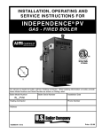
INSTALLATION, OPERATING AND SERVICE INSTRUCTIONS CGS-A™ Series GAS BOILER 9700609 BEFORE INSTALLATION: READ THIS MANUAL SAVE THESE INSTRUCTIONS Installing contractor and homeowner should read and be informed as to the proper installation and operation of this boiler. The manufacturer will not be responsible for improper installation or operation. This manual and all associated instruction material should be conspicuously posted near the boiler. F o r s e rvi c e o r re p a i rs to b o i le r, c a ll yo ur he a ti ng c o ntra c to r. W he n s e e k i ng i nfo rma ti o n o n b o i le r, p r o vi d e B o i le r Mo d e l Num b e r a nd S e ri a l Numb e r a s s ho wn o n Ra ti ng L a b e l. B o i le r Mo d e l Numb e r B o i le r S e r i a l Numb e r Ins ta lla ti o n D a te C GS _ 0 A He a ti ng C o ntr a c to r P ho ne Numb e r A d d re s s 104460-03 - 8/13 Price - $5.00 The City of New York requires a Licensed Master Plumber supervise the installation of this product. The Massachusetts Board of Plumbers and Gas Fitters has approved the Classic CGS-A™ Series boiler. See the Massachusetts Board of Plumbers and Gas Fitters website, http://license.reg.state.ma.us/pubLic/pl_products/pb_pre_form.asp for the latest Approval Code or ask your local Sales Representative. The Commonwealth of Massachusetts requires this product to be installed by a Licensed Plumber or Gas Fitter. The following terms are used throughout this manual to bring attention to the presence of hazards of various risk levels, or to important information concerning product life. DANGER CAUTION Indicates an imminently hazardous situation which, if not avoided, will result in death, serious injury or substantial property damage. Indicates a potentially hazardous situation which, if not avoided, may result in moderate or minor injury or property damage. WARNING NOTICE Indicates a potentially hazardous situation which, if not avoided, could result in death, serious injury or substantial property damage. Indicates special instructions on installation, operation, or maintenance which are important but not related to personal injury hazards. Figure 1: Dimensional Drawing Table 1: Dimensional Data Boiler Size 'A' 'B' CGS30A 12-3/16 4-3/4 CGS40A 15-3/4 4-3/4 CGS50A 19-3/8 5-1/4 CGS60A 22-7/8 5-1/4 CGS70A 26-1/2 7-1/2 CGS80A 30 7-1/2 Dimensions (in inches) 'E' 'C' 'D' Nat LP 4 5 6 6 7 7 6-1/8 7-7/8 9-3/4 11-1/2 13-1/4 15 53-1/8 50-1/4 52-1/8 53-3/8 55-7/8 57-1/8 53-1/8 50-1/4 55-1/8 56-3/8 58-7/8 60-3/4 Recommended Chimney * 'F' Nat LP Round Square 9-3/4 6 7-1/4 8-1/2 9-3/4 11 9-3/4 6 10-1/4 11-1/2 12-3/4 14-1/2 4" Dia. x 15 ft. 5" Dia. x 15 ft. 6' Dia. x 15 ft. 6' Dia. x 15 ft. 7' Dia. x 15 ft. 7' Dia. x 15 ft. 8" x 8" x 15 ft. 8" x 8" x 15 ft. 8" x 8" x 15 ft. 8" x 8" x 15 ft. 8" x 8" x 15 ft. 8" x 8" x 15 ft. * 15 Ft. Chimney height is from bottom of Draft Hood opening to top of chimney Maximum Working Pressure: 15 PSIG, Steam 30 PSIG, Water 2 Gas Approx. Connection Shipping (NPT) Weight 3/4 3/4 3/4 3/4 3/4 3/4 305 LB 370 LB 440 LB 502 LB 566 LB 650 LB Table of Contents I.Pre-Installation................................ 3 II. Unpack Boiler................................. 5 III. Steam Piping and Trim.................... 5 VIII.Service .......................................... 21 IV. Gas Piping....................................... 8 V.Venting.......................................... 10 VI.Electrical........................................ 13 VII. System Start-up............................. 16 IX. Repair Parts................................... 28 Warranty......................... Back Cover I. Pre-Installation WARNING Carefully read all instructions before installing boiler. Failure to follow all instructions in proper order can cause personal injury or death. A. Inspect shipment carefully for any signs of damage. All equipment is carefully manufactured, inspected and packed. Our responsibility ceases upon delivery of boiler to carrier in good condition. Any claim for damage or shortage in shipment must be filed immediately against carrier by consignee. No claims for variances or shortages will be allowed by Boiler Manufacturer, unless presented within sixty (60) days after receipt of equipment. Table 2: Special Base for Installation on Combustible Flooring Boiler Model Special Base Part Number CGS30A 61812036 CGS40A 61812046 CGS50A 61812056 CGS60A 61812066 CGS70A 61812076 CGS80A 61812086 B. Installation must conform to the requirements of the authority having jurisdiction. In the absence of such requirements, installation must conform to National Fuel Gas Code, ANSI Z223.1/NFPA 54. Where required by the authority having jurisdiction, the installation must conform to the Standard for Controls and Safety Devices for Automatically Fired Boilers, ANSI/ASME CSD-1. C. Boiler is design certified for installation on noncombustible flooring only. For installation on combustible flooring only when installed on special base listed in Table 2. The boiler must not be installed on carpeting. D. Provide clearance between boiler jacket and combustible material in accordance with local fire ordinance. Refer to Figure 2 for minimum clearance from combustible material for alcove installation. Figure 2: Minimum Clearances to Combustible Construction for Alcove Installation 3 I. Pre-Installation (continued) Recommended service clearance is 24 inches from left side, right side and front. Service clearances may be reduced to minimum clearances to combustible materials. E. Install on level floor. For basement installation provide concrete base if floor is not level or if water may be encountered on floor around boiler. F. Protect gas ignition system components from water (dripping, spraying, rain, etc.) during boiler operation and service (circulator replacement, condensate trap, control replacement, etc.). G. Provide combustion and ventilation air in accordance with applicable provisions of local building codes, or "Air for Combustion and Ventilation", of the National Fuel Gas Code, ANSI Z223.1/NFPA 54. 5. For boiler located in an unconfined space in a building of other than unusually tight construction, adequate combustion and ventilation air is normally provided by fresh air infiltration through cracks around windows and doors. 6. For boiler located within unconfined space in building of unusually tight construction or within confined space, provide outdoor air through two permanent openings which communicate directly or by duct with the outdoors or spaces (crawl or attic) freely communicating with the outdoors. Locate one opening within 12 inches of top of space. Locate remaining opening within 12 inches of bottom of space. Minimum dimension of air opening is 3 inches. Size each opening per following: a. Direct communication with outdoors. Minimum free area of 1 square inch per 4,000 Btu per hour input of all equipment in space. b. Vertical ducts. Minimum free area of 1 square inch per 4,000 Btu per hour input of all equipment in space. Duct cross-sectional area shall be same as opening free area. c. Horizontal ducts. Minimum free area of 1 square inch per 2,000 Btu per hour input of all equipment in space. Duct cross-sectional area shall be same as opening free area. WARNING Adequate combustion and ventilation air must be provided to assure proper combustion. 54. The following guideline is based on the National Fuel Gas Code, ANSI Z223.1/NFPA 54. 1. Determine volume of space (boiler room). Rooms communicating directly with space (through openings not furnished with doors) are considered part of space. Volume [ft³] = Length [ft] x Width [ft] x Height [ft] 2. Determine Total Input of all appliances in space. Round result to nearest 1,000 Btu per hour (Btuh). 3. Determine type of space. Divide Volume by Total Input. a. If result is greater than or equal to 50 ft³ per 1,000 Btuh, space is considered an unconfined space. b. If result is less than 50 ft³ per 1,000 Btuh, space is considered a confined space. 4. Determine building type. A building of unusually tight construction has the following characteristics: a. Walls and ceiling exposed to outside atmosphere have a continuous water vapor retarder with a rating of 1 perm or less with openings gasketed and sealed, and; b. Weather-stripping has been added on openable windows and doors, and; c. Caulking or sealants applied in joints around window and door frames, between sole plates and floors, between wall-ceiling joints, between wall panels, at plumbing and electrical penetrations, and at other openings. 4 Alternate method for boiler located within confined space. Use indoor air if two permanent openings communicate directly with additional space(s) of sufficient volume such that combined volume of all spaces meet criteria for unconfined space. Size each opening for minimum free area of 1 square inch per 1,000 Btu per hour input of all equipment in spaces, but not less than 100 square inches. 7. Ventilation Duct Louvers and Grilles. Equip outside openings with louvers to prevent entrance of rain and snow, and screens to prevent entrance of insects and rodents. Louvers and grilles must be fixed in open position or interlocked with equipment to open automatically before burner operation. Screens must not be smaller than ¼ inch mesh. Consider the blocking effect of louvers, grilles and screens when calculating the opening size to provide the required free area. If free area of louver or grille is not known, assume wood louvers have 20-25 percent free area and metal louvers and grilles have 60-75 percent free area. H. Do not install boiler where gasoline or other flammable vapors or liquids, or sources of hydrocarbons (i.e. bleaches, cleaners, chemicals, sprays, paint removers, fabric softeners, etc.) are used or stored. II. Unpack Boiler 1. Place base on floor with insulated surface facing upward and part number facing forward. CAUTION 2. Position base to provide minimum clearances to combustible walls. See Figure 3. Secure in place. Do not drop boiler. Do not bump boiler jacket against floor. 3. Place boiler on base. Center boiler on base to provide minimum clearances to combustible walls and ceiling. See Figure 2. A. Move boiler to approximate installed position. B. Remove crate. 1. Remove nails and staples from crate. 2. Remove four carriage bolts holding boiler to skid. 3. Remove boiler from skid using ¾ inch pipe rollers. a. Roll boiler to rear of skid. Handle boiler jacket carefully to avoid damage. b. Lower rear of boiler to floor. c. Tilt boiler, remove skid at front of boiler, and lower front of boiler to floor. Do not drop boiler. C. Move boiler to permanent location. When using special base for installation on combustible floor: Figure 3: Special Base Installation III. Steam Piping and Trim NOTICE Before using copper for steam piping, consider the following characteristics of copper piping: 1) High coefficient of thermal expansion can induce mechanical stresses and cause expansion/ contraction noises if not accounted for in the piping system design and installation, 2) High heat transfer rate (heat loss) of uninsulated copper piping must be included in the normal piping and pickup factors used to size the boiler, 3) Soldering or brazing pastes and fluxes that end up in the system can cause poor heat transfer, surging, an unsteady water line and wet steam if not thoroughly removed during boil out procedure and, 4) Galvanic corrosion of the adjoining metal may occur due to dissimilar metals in certain water chemistries if dielectric unions are not used. WARNING Failure to properly pipe boiler may result in improper operation and damage to boiler or structure. A. Design and install boiler and system piping to prevent oxygen contamination of boiler water. Oxygen contamination sources are system leaks requiring addition of makeup water, fittings, and oxygen permeable materials in distribution system. Eliminate oxygen contamination by repairing system leaks, repairing fittings, and using nonpermeable materials in distribution system. B. Boiler equipped with McDonnell & Miller 67 Low Water Cutoff Only. Assemble gauge glass and low water cutoff as shown in Figure 5. Follow instructions packed with low water cutoff. 1. Affix Blow-Down Card to Jacket Left Side Panel adjacent to low water cutoff. 2. Provide blow-down discharge piping. C. Remove Jacket Front Panel. Remove parts bag from vestibule area. D. Install Safety Valve in Tapping 'E'. See Figure 4. Use ¾ NPT x 3" nipple and ¾ elbow provided. Safety Valve must be installed with spindle in vertical position. 5 III. Steam Piping and Trim (continued) WARNING Safety valve discharge piping must be piped near floor to eliminate potential of severe burns. Do not pipe in any area where freezing could occur. Do not install any shut-off valves. E. Install Drain Valve in Tapping 'F'. See Figure 4. Table 3: Purpose of Tappings Tapping Size Purpose A 2" 30 - 70: Plugged, Optional Second Supply 80: Second Supply B ¾" Pressure Gauge (bushed to ¼) C ½" Gauge Glass / Float LWCO D 2" Return (Standard) E ¾" Safety Valve F 2" Drain Valve Return (Alternate) G 2" Supply H ¾" Limit K ¾" Probe Low Water Cutoff (Plugged with McDonnell & Miller 67 LWCO) F. Connect system supply and return piping to boiler. Figure 4: Purpose of Tappings 6 1. See Figure 6. Also consult Residential Hydronic Heating Installation and Design I=B=R Guide. Maintain minimum ½ inch clearance from piping to combustible materials. Figure 5: Assembly Diagram for McDonnell & Miller 67 Low Water Cutoff III. Steam Piping and Trim (continued) Figure 6: Recommended Boiler Piping for Gravity Return 2. If boiler is used in connection with refrigeration systems, boiler must be installed with chilled medium piped in parallel with heating boiler using appropriate valves to prevent the chilled medium from entering the boiler. See Figure 7. Also consult I=B=R, "Residential Hydronic Heating Installation and Design Guide". 3. Boiler piping system of hot water boiler connected to heating coils located in air handling units where they may be exposed to refrigerated air circulation must be equipped with flow control valves or other automatic means to prevent gravity circulation of boiler water during cooling cycle. Figure 7: Recommended Piping for Combination Heating and Cooling (Refrigeration) Systems 7 IV. Gas Piping A. Size gas piping. Design system to provide adequate gas supply to boiler. Consider these factors: 1. Allowable pressure drop from point of delivery to boiler. Maximum allowable system pressure is ½ psig. Actual point of delivery pressure may be less; contact gas supplier for additional information. Minimum gas valve inlet pressure is listed on rating label. For materials or conditions other than those listed above, refer to National Fuel Gas Code, ANSI Z223.1/ NFPA 54, or size system using standard engineering methods acceptable to authority having jurisdiction. B. Connect boiler gas valve to gas supply system. 1. Use methods and materials in accordance with local plumbing codes and requirements of gas supplier. In absence of such requirements, follow National Fuel Gas Code, ANSI Z223.1/NFPA 54. 2. Maximum gas demand. Table 4 lists boiler input rate. Also consider existing and expected future gas utilization equipment (i.e. water heater, cooking equipment). 2. Use thread (joint) compounds (pipe dope) resistant to action of liquefied petroleum gas. 3. Install sediment trap, ground-joint union and manual shut-off valve upstream of boiler gas control valve. See Figure 8. 3. Length of piping and number of fittings. Refer to Table 5 for maximum capacity of Schedule 40 pipe. Table 6 lists equivalent pipe length for standard fittings. 4. Corrections for the specific gravity of natural gas can be found in Table 7. Table 4: Rated Input Input Rate [cubic feet per hour] Boiler Model Number Natural LP/Propane Gas Connection Size CGS30S 70 28 ¾ CGS40A 105 42 ¾ CGS50A 140 56 ¾ CGS60A 175 70 ¾ CGS70A 210 84 ¾ CGS80A 245 98 ¾ Figure 8: Pilot and Gas Piping, Table 5: Maximum Capacity of Schedule 40 Pipe in CFH For Natural Gas Pressures of 0.5 psig or Less 8 0.3 inch w.c. Pressure Drop 0.5 inch w.c. Pressure Drop Length\ [Feet] ½ ¾ 1 1¼ ½ ¾ 1 1¼ 10 132 278 520 1,050 175 360 680 1,400 20 92 190 350 730 120 250 465 950 30 73 152 285 590 97 200 375 770 40 63 130 245 500 82 170 320 660 50 56 115 215 440 73 151 285 580 60 50 105 195 400 66 138 260 530 70 46 96 180 370 61 125 240 490 80 43 90 170 350 57 118 220 460 90 40 84 160 320 53 110 205 430 100 38 79 150 305 50 103 195 400 IV. Gas Piping (continued) Table 6: Fitting Equivalent Lengths Fitting Table 7: Specific Gravity Correction Factors for Natural Gas Nominal Pipe Size ½ ¾ 1 1¼ 45° Ell 0.7 1.0 1.2 1.6 90° Ell 1.6 2.1 2.6 3.5 Tee (As Elbow) 3.1 4.1 5.2 6.9 4. All above ground gas piping upstream from manual shut-off valve must be electrically continuous and bonded to a grounding electrode. Do not use gas piping as grounding electrode. Refer to National Electrical Code, ANSI/NFPA 70. C. Pressure test. The boiler and its gas connection must be leak tested before placing boiler in operation. Specific Gravity Correction Factor Specific Gravity Correction Factor 0.50 1.10 1.30 1.07 0.55 1.04 1.40 1.04 0.60 1.00 1.50 1.00 0.65 0.96 1.60 0.97 0.70 0.93 1.70 0.94 0.75 0.90 0.80 0.87 2. Locate leaks using approved combustible gas detector, soap and water, or similar nonflammable solution. Do not use matches, candles, open flames, or other ignition source. 1. Protect boiler gas control valve. For all testing over ½ psig, boiler and its individual shutoff valve must be disconnected from gas supply piping. For testing at ½ psig or less, isolate boiler from gas supply piping by closing boiler's individual manual shutoff valve. 9 V. Venting A.Install vent system in accordance with local building codes; or local authority having jurisdiction; or National Fuel Gas Code, ANSI Z223.1/NFPA 54, Part 7, Venting of Equipment. Install any of the following for this Classic CGS-A Series Category I, draft hood equipped appliance: 1. Type B or Type L gas vent. Install in accordance with listing and manufacturer's instructions. 2. Masonry or metal chimney. Build and install in accordance with local building codes; or local authority having jurisdiction; or Standard for Chimneys, Fireplaces, Vents, and Solid Fuel Burning Appliances, ANSI/NFPA 211. Masonry chimney must be lined with approved clay flue lining or listed chimney lining system. 3. Single wall metal vent. Allowed by ANSI Z223.1/ NFPA 54 under very restrictive conditions. 4. Do not use cellular core PVC (ASTM F891), cellular core CPVC, or Radel® (polyphenolsulfone). 5. Do not cover non-metallic vent pipe and fittings with thermal insulation. Note: Non-metallic vent cannot be used with this boiler. B. Inspect chimney and remove any obstructions or restrictions. Clean chimney if previously used for solid or liquid fuel-burning appliances or fireplaces. DANGER Inspect existing chimney before installing boiler. Failure to clean or replace perforated pipe or tile lining will cause severe injury or death. C. Install Draft Hood without modification on outlet of flue collector. See Figure 1. Secure with sheet metal screws. WARNING Do not alter boiler draft hood or place any obstruction or non-approved damper in the breeching or vent system. Flue gas spillage can occur. ETL certification will become void. D. Install Blocked Vent Switch. The Blocked Vent Switch Assembly shipped taped to top of boiler includes power cord and switch attached to mounting bracket. 10 Figure 9: Blocked Vent Switch Installation 1. Untape Blocked Vent Switch Assembly from top of boiler. Uncoil power cord. 2. Pinch black strain relief bushing installed in Jacket Right Side Panel to dislodge bushing from jacket. Pull out enough power cord so Blocked Vent Switch Assembly reaches near side of Draft Hood skirt. Do not pull out more power cord than necessary. 3. Position mounting bracket onto lower edge of Draft Hood skirt. Locate center tooth (with #10 sheet metal screw) on outside and other two teeth inside Draft Hood skirt. See Figure 9. 4. Slide mounting bracket tight against lower edge of Draft Hood skirt. Position #10 sheet metal screw above skirt's stiffening rib. 5. Secure bracket in position by tightening #10 sheet metal screw against outer surface of Draft Hood skirt. 6. Insert excess power cord through Jacket Right Side Panel hole. Remove slack. 7. Position strain relief bushing around power cord. Pinch bushing's two halves together and snap back into hole in Jacket Right Side Panel. 8. Verify power cord, mounting bracket and Blocked Vent Switch are secure and located as shown in Figure 9. V. Venting (continued) WARNING Failure to properly install and use this Blocked Vent Switch may result in property damage, personal injury or loss of life. E. Install Vent Damper. See Figure 10. 1. Open Vent Damper Carton and remove Installation Instructions. Read Installation Instructions thoroughly before proceeding. NOTICE Please refer to the specifications, installation instructions and troubleshooting guide packed in the vent damper carton for complete detailed installation instructions. 2. Vent damper should be same size as draft hood outlet. See Figure 1. Unpack vent damper carefully - DO NOT FORCE CLOSED! Forcing vent damper may damage gear train and void warranty. Vent damper assembly includes pre-wired connection harness with polarized plug for use on all EI control systems. 3. Mount vent damper assembly on draft hood without modification to either. Refer to instructions packed with vent damper for specific instructions. Vent damper position indicator to be visible to users. CAUTION Provide adequate clearance for servicing provide 6" minimum clearance between damper and combustible construction. CAUTION Do not use one vent damper to control two heating appliances. Figure 10: Vent Damper Installation 11 V. Venting (continued) F. Install Vent Connector from vent damper to chimney or gas vent. See Figure 11. 1. Do not connect into same leg of chimney serving an open fireplace. 2. Vent connector must not be smaller than vent damper outlet. Type B is recommended, but singlewall vent pipe may be used. Arrange venting system so only the boiler is served by vent damper device. 3. Do not connect vent connectors serving appliances vented by natural draft into any portion of mechanical draft system operating under positive pressure. 4. Where two or more appliances vent into a common vent, the area of the common vent should be at least equal to the area of the largest vent plus 50% of the area in the additional vent(s). 5. Vent connector should have greatest possible initial rise above vent damper consistent with headroom available and required clearance from adjacent combustible building structure. 6. Slope horizontal portions of vent pipe upwards not less than 1/4 in/ft from boiler to vent terminal. 7. Support horizontal portions of venting system to prevent sagging. Use pipe straps, brackets or hangers spaced 4 ft. or less. 8. Vent connector should be installed above bottom of chimney to prevent blockage. Inserted into but not beyond inside wall of chimney liner. Seal tight between vent connector and chimney. venting system are located and other spaces of the building. Turn on clothes dryers and any appliance not connected to the common venting system. Turn on any exhaust fans, such as range hoods and bathroom exhausts, so they will operate at maximum speed. Do not operate a summer exhaust fan. Close fireplace dampers. d. Place in operation the appliance being inspected. Follow the Lighting Instructions. Adjust thermostat so appliance will operate continuously. e. Test for spillage at the draft hood relief opening after 5 minutes of main burner operation. Use the flame of a match or candle, or smoke from a cigarette, cigar or pipe. f. After it has been determined that each appliance remaining connected to the common venting system properly vents when tested as outlined above, return doors, windows, exhaust fans, fireplace dampers and any other gas-burning appliance to their previous condition of use. g. Any improper operation of the common venting system should be corrected so the installation conforms with the National Fuel Gas Code, ANSI Z223.1/NFPA 54. When resizing any portion of the common venting system, the common venting system should be resized to approach the minimum size as determined using the appropriate tables in Chapter 13 of the National Fuel Gas Code, ANSI Z223.1/NFPA 54. G. If an Existing Boiler is Removed: When an existing boiler is removed from a common venting system, the common venting system is likely to be too large for proper venting of the appliances remaining connected to it. At the time of removal of an existing boiler, the following steps shall be followed with each appliance remaining connected to the common venting system placed in operation, while the other appliances remaining connected to the common venting system are not in operation: a. Seal any unused openings in the common venting system. b. Visually inspect the venting system for proper size and horizontal pitch and determine there is no blockage or restriction, leakage, corrosion, and other deficiencies which could cause an unsafe condition. c. Insofar as is practical, close all building doors and windows and all doors between the space in which the appliances remaining connected to the common 12 Figure 11: Typical Vent System Installation VI. Electrical A. General. Install wiring and electrically bond boiler to ground in accordance with requirements of authority having jurisdiction, or in absence of such requirements, the National Electrical Code, ANSI/NFPA 70. Table 8: Wiring Diagrams B. Connect Vent Damper. See Figure 10. Ignition System Low Water Cutoff Intermittent (EI) 24V Probe X 13 Float X 14 1. Carefully remove Transformer from Junction Box. Figure No. 2. Remove 7/8" knockout from top of Junction Box. 3. Attach Vent Damper wiring harness into top of Junction Box. F. Wire boiler. Boiler is rated for 120 VAC, 60 hertz, less than 12 amperes. Provide individual branch circuit with fused disconnect. Connect to black and white wires and green ground screw. Install Transformer on Junction Box. 4. Connect Vent Damper Wiring Harness to Vent Damper Receptacle. C. Wire Low Water Cutoff (McDonnell & Miller 67 Only). Attach Black wire to Terminal '1'. Attach BlackWhite wire to Terminal '2'. G. Vent Damper Sequence of Operation. See Figure 12. 1. Vent Damper continuously powered at Terminal 1. D. Install thermostat. Locate on inside wall approximately 4 feet above floor. Do not install on outside wall, near fireplace, or where influenced by drafts or restricted air flow, hot or cold water pipes, lighting fixtures, television, or sunlight. Allow free air movement by avoiding placement of furniture near thermostat. 2. Call for heat energizes Vent Damper through Terminal 5. 3. Vent Damper reaches fully open position. Power is sent back to gas control circuit through Terminal 2. 4. Call for heat ends. Vent Damper closes. E. Wire thermostat. Provide Class II circuit between thermostat and boiler. Connect to Blue transformer lead and Brown relay lead. Set thermostat heat anticipator to 0.4 amps. If system tends to overheat above thermostat's temperature setting, reduce heat anticipator setting by 0.1 or 0.2 amps. If system tends to shortcycle without reaching desired room temperature, increase heat anticipator setting by 0.1 or 0.2 amps. Note: After Vent Damper is installed and operated through one cycle, the control circuit will operate only when Vent Damper is connected in control circuit. CAUTION This boiler contains controls which may cause the boiler to shut down and not restart without service. If damage due to frozen pipes is a possibility, the heating system should not be left unattended in cold weather; or appropriate safeguards and alarms should be installed on the heating system to prevent damage if the boiler is inoperative. Figure 12: Vent Damper Schematic Wiring Diagram 13 VI. Electrical (continued) Figure 13: Wiring Diagram, Intermittent Ignition (EI) and Hydrolevel Model 400 or McDonnell & Miller PS-802-24 Low Water Cutoff do not attempt to place boiler in operation. The I. Sequence of Operation with Intermittent Ignition (EI). source of blockage must be corrected by trained and 1. Normal Operation skilled personnel from a qualified service agency a. Thermostat calls for heat. Vent Damper opens. Vent before resetting switch. damper must be in open position when appliance d. Flame Roll-out Switch. Automatically interrupts main burners are operating. boiler operation when flames or excessive heat are b. Ignition Module energized. Pilot Valve opens. present in vestibule. Vent Damper remains open with Igniter energized to ignite Pilot Burner. call for heat. Control is single use device. If flame c. Sensor proves presence of pilot flame. Main Valve roll-out switch is activated do not attempt to place opens and ignites Main Burners. boiler in operation. The source of blockage must be corrected and the flame roll-out switch replaced d. Call for heat ends. Ignition Module is de-energized. by trained and skilled personnel from a qualified Main Valve and Pilot Valve close, extinguishing service agency. pilot and main burners. Vent Damper closes. e. Sensor: senses pilot flame and causes ignition 2. Safety Shutdown module to turn off main burner and pilot burner gas a. Low Water Cutoff. Automatically interrupts main flow should pilot burner flame extinguish. Ignition burner operation when surface of boiler water falls module will try to relight pilot for approximately 85 to lowest permissible operating level. Vent damper seconds after pilot burner flame is extinguished. If closes. Normal operation resumes when water pilot burner flame can not be reestablished, Ignition returns to normal level. Module will shutdown. b. Limit: Automatically interrupts main burner Five to six minutes after shutdown, Ignition Module operation when steam pressure exceeds set point. automatically restarts ignition sequence. Sequence Maximum allowable pressure is 15 psi. Vent Damper continues until pilot burner flame is reestablished or closes. Normal operation resumes when steam call for heat ends. Ignition Module can be manually pressure falls below set point. reset by adjusting thermostat to end call for heat c. Blocked Vent Switch. Automatically interrupts for one minute. main burner operation when excessive vent system Vent Damper remains open with call for heat. blockage occurs. Vent Damper remains open with For Electronic Ignition Troubleshooting Guide, see call for heat. If blocked vent switch is activated Figure 21. 14 VI. Electrical (continued) Figure 14: Wiring Diagram, Intermittent Ignition (EI) and McDonnell & Miller 67 Low Water Cutoff not attempt to place boiler in operation. The source K. Sequence of Operation with Intermittent Ignition (EI). of blockage must be corrected by trained and skilled 1. Normal Operation personnel from a qualified service agency before a. Thermostat calls for heat. Vent Damper opens. Vent resetting switch. damper must be in open position when appliance d. Flame Roll-out Switch. Automatically interrupts main burners are operating. boiler operation when flames or excessive heat are b. Ignition Module energized. Pilot Valve opens. present in vestibule. Vent Damper remains open with Igniter energized to ignite Pilot Burner. call for heat. Control is single use device. If flame c. Sensor proves presence of pilot flame. Main Valve roll-out switch is activated do not attempt to place opens and ignites Main Burners. boiler in operation. The source of blockage must be corrected and the flame rollout switch replaced d. Call for heat ends. Ignition Module is de-energized. by trained and skilled personnel from a qualified Main Valve and Pilot Valve close, extinguishing service agency. pilot and main burners. Vent Damper closes. e. Sensor: senses pilot flame and causes ignition 2. Safety Shutdown module to turn off main burner and pilot burner gas a. Low Water Cutoff. Automatically interrupts main flow should pilot burner flame extinguish. Ignition burner operation when surface of boiler water falls module will try to relight pilot for approximately 85 to lowest permissible operating level. Vent damper seconds after pilot burner flame is extinguished. If closes. Normal operation resumes when water pilot burner flame can not be reestablished, Ignition returns to normal level. Module will shutdown. b. Limit: Automatically interrupts main burner Five to six minutes after shutdown, Ignition Module operation when steam pressure exceeds set point. automatically restarts ignition sequence. Sequence Maximum allowable pressure is 15 psi. Vent Damper continues until pilot burner flame is reestablished or closes. Normal operation resumes when steam call for heat ends. Ignition Module can be manually pressure falls below set point. reset by adjusting thermostat to end call for heat c. Blocked Vent Switch. Automatically interrupts for one minute. main burner operation when excessive vent system Vent Damper remains open with call for heat. blockage occurs. Vent Damper remains open with For Electronic Ignition Troubleshooting Guide, see call for heat. If blocked vent switch is activated do Figure 21. 15 VII. System Start-up A. Safe operation and other performance criteria were met with gas manifold and control assembly provided on boiler when boiler underwent tests specified in American National Standard for Gas-Fired LowPressure Steam and Hot Water Boilers, ANSI Z21.13. B. Check main burners. Rear of burner must be in vertical slot in rear of burner tray. Front of burner must be seated on orifice. C. Fill boiler with water to normal water line. D. Prepare to check operation. 1. Obtain gas heating value (in Btu per cubic foot) from gas supplier. 2. Adjust limit. Adjust cut-in pressure for 2 psi and differential for 1 psi. 3. Connect manometer to outlet pressure tap on gas valve. 4. For natural gas-fired boiler, temporarily turn off all other gas-fired appliances. Figure 15: Pilot Burner Flame, Intermittent Ignition E. Follow Operating Instructions to place boiler in operation. See Figure 17. F. Sequence of Operation is located under wiring diagram. See Table 8. If boiler fails to operate properly, see Figure 21 for Troubleshooting Guide. G. Test gas piping and connections between Gas Valve and Manifold, orifices, and pilot tubing while boiler is operating. Locate leaks using approved combustible gas detector, soap and water, or similar nonflammable solution. Do not use matches, candles, open flames, or other ignition source. H. Check pilot burner flame. See Figure 15. Pilot produces three (3) flames. Center flame should be steady, medium hard blue enveloping 3/8 to ½ inch of sensing probe. I. Check main burner flame. See Figure 16. Flame should have clearly defined inner cone with no yellow tipping. Orange-yellow streaks should not be confused with true yellow tipping. J. Check thermostat operation. Raise and lower temperature setting to start and stop boiler operation. K. Check ignition system shutoff. Disconnect Ignition/ sensor cable from Terminal 9 (Spark). Gas valve should close and pilot and main burners should extinguish. L. Low Water Cutoff. 1. Adjust thermostat to highest setting. 2. With boiler operating, open drain valve and slowly drain boiler. 16 Figure 16: Main Burner Flame CAUTION Do not drain below gauge glass. 3. Main burners and pilot burner will extinguish when water level falls below low water cutoff (water should still be visible in gauge glass). Verify limit, thermostat or other controls have not shut off boiler. CAUTION Avoid operating this boiler in an environment where saw dust, loose insulation fibers, dry wall dust, etc. are present. If boiler is operated under these conditions, the burner interior and ports must be cleaned and inspected daily to insure proper operation. VII. System Start-up (continued) 4. Adjust thermostat to lowest setting. Refill boiler to normal water line. M. Check limit. NOTICE 3. Adjust limit to setting above observed pressure. Ignition sequence should begin. CGS-A boilers built for installation at altitudes greater than 2,000 feet above sea level have been specially orificed to reduce gas input rate 4 percent per 1,000 feet above sea level per the National Fuel Gas Code, ANSI Z223.1/NFPA 54, Section 8.1.2 and Appendix F. High altitude boiler models are identifiable by the third digit in the model number suffix on the rating label: 4. Adjust thermostat to lowest setting. Adjust limit to desired setting. CGS _ OA _ _ - _ _ 2: less than 2000 ft. elevation CGS _ OA _ _ - _ _ 5: 2000 to 5000 ft. elevation 1. Adjust thermostat to highest setting. 2. Observe pressure gauge. When pressure is indicated, adjust limit to setting below observed pressure. Main burners should extinguish. N. Check Vent Damper Operation. Vent Damper must be in open position when main burners are ignited. O. Adjust gas input rate to boiler (Natural Gas). 1. Adjust thermostat to highest setting. 2. Check manifold gas pressure. Manifold pressure is listed on rating label. Adjust gas valve pressure regulator as necessary (turn adjustment screw counterclockwise to decrease manifold pressure, or clockwise to increase manifold pressure). If pressure can not be attained, check gas valve inlet pressure. If less than minimum gas supply pressure listed on rating label, contact gas supplier for assistance. Table 9: Gas Flow Rate in Cubic Feet per Hour Size of Gas Meter Dial Seconds for One One-Half One Two Five Revolution Cu. Ft. Cu. Ft. Cu. Ft. Cu. Ft. 30 60 120 240 600 32 56 113 225 563 34 53 106 212 529 36 50 100 200 500 38 47 95 189 474 3. Clock gas meter for at least 30 seconds. Use Table 9 to determine gas flow rate in Cubic Feet per Hour. 40 45 90 180 450 4. Determine Input Rate. Multiply gas flow rate by gas heating value. 42 43 86 172 430 44 41 82 164 410 46 39 78 157 391 48 37 75 150 375 50 36 72 144 360 52 35 69 138 346 54 33 67 133 333 56 32 64 129 321 58 31 62 124 310 60 30 60 120 300 62 29 58 116 290 64 29 56 112 281 66 29 54 109 273 68 28 53 106 265 70 26 51 103 257 72 25 50 100 250 74 24 48 97 243 76 24 47 95 237 78 23 46 92 231 80 22 45 90 225 5. Compare measured input rate to input rate listed on rating label. a. Boiler must not be overfired. Reduce input rate by decreasing manifold pressure. Do not reduce more than 0.3 inch w.c. If boiler is still overfired, contact New Yorker Boiler Company for replacement Gas Orifices. b. Increase input rate if less than 98% of rating label input. Increase manifold gas pressure no more than 0.3 inch w.c. If measured input rate is still less than 98% of rated input: i. Remove Main Burners per procedure in Section VIII. Service. ii. Remove gas orifices. Drill one (1) drill size larger (drill size is stamped on orifice, or see Section IX. Repair Parts). iii. Reinstall gas orifices and main burners. Measure input rate. 6. Recheck Main Burner Flame. 7. Follow instructions to TURN OFF GAS TO APPLIANCE. See Figure 17. Remove manometer. 17 VII. System Start-up (continued) Figure 17: Operating Instructions 8. Follow Operating Instructions to place boiler in operation. See Figure 17. Adjust thermostat to normal setting. 3. Recheck Main Burner Flame 9. Return other gas-fired appliances to previous conditions of use. 5. Follow Operating Instructions to place boiler in operation. See Figure 17. Adjust thermostat to normal setting. P. Adjust gas input rate to boiler (LP/Propane). 1. Adjust thermostat to highest setting. 2. Check manifold pressure. Adjust gas valve pressure regulator to obtain 10 inches w.c. manifold pressure. Adjust gas valve pressure regulator as necessary (turn adjustment screw counterclockwise to decrease manifold pressure, or clockwise to increase manifold pressure). If pressure can not be attained, check gas valve inlet pressure. If less than minimum gas supply pressure listed on rating label, contact gas supplier for assistance. 18 4. Follow instructions to TURN OFF GAS TO APPLIANCE. See Figure 17. Remove manometer. Q. Clean Heating System. Oil from new piping connections and sediment in existing piping must be removed from the system to prevent unsteady water line and carry-over of entrained water into supply main. 1. Fill boiler to normal waterline. 2. Follow Operating Instructions to place boiler in operation. See Figure 17. 3. Operate the boiler with steam in the entire system for several days to bring system oil and dirt back to the boiler. VII. System Start-up (continued) 4. Drain condensate from drain valve in wet return. Operate boiler until condensate runs clean. R. Boil-out boiler. 1. Follow instructions TO TURN OFF GAS TO APPLIANCE. See Figure 17. 2. Drain boiler until 1" of water is visible in gauge glass. 3. Run temporary hose or piping from boiler drain valve to an open drain or some other location where hot water may be discharged safely. Do not install valve in this line. 4. Drain about 5 gallons of hot water from boiler into a container and dissolve into it an appropriate amount of recommended boil out compound. Remove safety valve and add solution to boiler water through exposed tapping using a funnel. NOTICE Check with local authorities or consult local water treatment services for acceptable chemical cleaning compounds. 5. Run temporary hose or piping from boiler tapping "E" to an open drain or some other location where hot water may be discharged safely. Do not install valve in this line (See Figure 4). 6. Follow Operating Instructions to place boiler in operation. See Figure 17. 7. Operate sufficiently to boil the water without producing steam pressure. Boil for about 5 hours. Open boiler fill valve sufficiently to permit a steady trickle of water from the pipe. Continue this slow boiling and trickle of overflow for several hours until the water coming from the overflow is clear. 8. Follow instructions TO TURN OFF GAS TO APPLIANCE. See Figure 17. 9. Drain boiler in a manner and to a location that hot water can be discharged with safety. 10.Refill boiler to normal water line. If water in gauge glass does not appear to be clear, repeat steps (1 thru 3) and boil out the boiler for a longer time. S. Second Boilout for Stubborn Cases. If unsteady water line, foaming or priming persist, proceed as follows: 1. Connect hoses from boiler and return main drain valves to floor drain. Close shut off valve in Hartford Loop and open drain valve in return main. Fill boiler to normal water level. 2. Follow Operating Instructions to place boiler in operation. See Figure 17. 3. Operate boiler at this water level for at least 30 minutes after the condensate begins to run hot. 4. Follow instructions TO TURN OFF GAS TO APPLIANCE. See Figure 17. 5. Close all radiator valves. Remove all supply main air valves and plug the openings in supply main. 6. Draw about 5 gallons of hot water from boiler into a container and dissolve into it the appropriate amount of a recommended boilout compound. Remove safety valve from boiler and pour this solution into boiler, then reinstall safety valve. 7. Follow Operating Instructions to place boiler in operation. See Figure 17. 8. Keep operating boiler while feeding water to boiler slowly. This will raise water level in boiler slowly so that water will be boiling hot and will rise slowly into supply main and back through return main, flowing from drain hose at about 180°F. Continue until water runs clear from drain hose for at least 30 minutes. 9. Stop feeding water to boiler but continue operating boiler until excess water in boiler flows out through supply main and water lowers (by steaming) until it reaches normal level in boiler. 10.Follow instructions to TURN OFF GAS TO APPLIANCE. See Figure 17. 11.Drain boiler. Open all radiator valves. Reinstall all supply main air valves. Open shut off valve in Hartford Loop. 12.When boiler has cooled down sufficiently (iron sections are not too hot to touch), close the drain valves at boiler and in return main and feed water slowly up to normal level in boiler. 13.Follow Operating Instructions to place boiler in operation. See Figure 17. 14.Allow boiler to steam for 10 minutes. 15.Follow instructions to TURN OFF GAS TO APPLIANCE. See Figure 17. 16.Draw off one quart of water from bottom gauge glass fitting and discard. Draw off another quart sample and if this sample is not clear, repeat the cycle of draining the boiler and return main and refilling the boiler until sample is clear. If the boiler water becomes dirty again at a later date due to additional sediment loosened up in the piping: 1. Follow instruction to TURN OFF GAS TO APPLIANCE. See Figure 17. 2. Close shut off valve in Hartford Loop and open drain valve in return main. 19 VII. System Start-up (continued) 3. Follow Operating Instructions to place boiler in operation. See Figure 17. 4. Allow condensate to flow to drain until it has run clear for at least 30 minutes while feeding water to boiler so as to maintain normal water level. 5. Follow instructions to TURN OFF GAS TO APPLIANCE. See Figure 17. 6. Drain boiler, open shut off valve in Hartford Loop, then repeat step R. above. T. Add Boiler Water Treatment. 1. Low pressure steam boilers such as this CGS-A Series should be maintained with appropriate water treatment compounds. Add suitable water treatment compounds as recommended by your qualified water treatment company. 2. Remove temporary drain valve and overflow piping and reinstall safety valve. Boil or bring water temperature to 180°F promptly in order to drive off the dissolved gases in the fresh water. 3. Make pH or Alkalinity Test. After boiler and system have been cleaned and refilled as previously described, test the pH of the water in the system. This can easily be done by drawing a small sample of boiler water and testing with hydrion dispenser gives the reading in pH. Hydrion paper is inexpensive and obtainable from any chemical supply house or through your local druggist. The pH should be higher than 7, but lower than 11. Add some of the washout chemical, if necessary, to bring the pH within the specified range. 4. Boiler is now ready to be put into service. 20 U. Combustion Chamber Burn-off 1. The mineral wool combustion chamber panels contain a cornstarch based binder that must be burned out a installation to prevent odors during subsequent boiler operation. 2. Ventilate the boiler room, set the high limit to its maximum setting, set the thermostat to call for heat. Allow the boiler to fire for at least an hour or until the odor from the cornstarch has dissipated. 3. Return the high limit and thermostat to their desired settings. V. Review User's Information Manual and system operation with owner or operator. W. Post instructions near boiler for reference by owner and service personnel. Maintain instructions in legible condition. VIII. Service Important Product Safety Information Refractory Ceramic Fiber Product Warning: The Repair Parts list designates parts that contain refractory ceramic fibers (RCF). RCF has been classified as a possible human carcinogen. When exposed to temperatures about 1805°F, such as during direct flame contact, RCF changes into crystalline silica, a known carcinogen. When disturbed as a result of servicing or repair, these substances become airborne and, if inhaled, may be hazardous to your health. AVOID Breathing Fiber Particulates and Dust Precautionary Measures: Do not remove or replace RCF parts or attempt any service or repair work involving RCF without wearing the following protective gear: 1. A National Institute for Occupational Safety and Health (NIOSH) approved respirator 2. Long sleeved, loose fitting clothing 3. Gloves 4. Eye Protection • • • • Take steps to assure adequate ventilation. Wash all exposed body areas gently with soap and water after contact. Wash work clothes separately from other laundry and rinse washing machine after use to avoid contaminating other clothes. Discard used RCF components by sealing in an airtight plastic bag. RCF and crystalline silica are not classified as hazardous wastes in the United States and Canada. First Aid Procedures: • • • • If contact with eyes: Flush with water for at least 15 minutes. Seek immediate medical attention if irritation persists. If contact with skin: Wash affected area gently with soap and water. Seek immediate medical attention if irritation persists. If breathing difficulty develops: Leave the area and move to a location with clean fresh air. Seek immediate medical attention if breathing difficulties persist. Ingestion: Do not induce vomiting. Drink plenty of water. Seek immediate medical attention. 21 VIII. Service (continued) WARNING Service on this boiler should be undertaken only by trained and skilled personnel from a qualified service agency. Inspections should be performed at intervals specified in this manual. Maintain manual in a legible condition. Keep boiler area clear and free of combustible materials, gasoline and other flammable vapors and liquids. Do not place any obstructions in boiler room that will hinder flow of combustion and ventilation air. A.General. Inspection and service should be conducted annually, except as noted. Turn off electrical power and gas supply while conducting service or maintenance. Follow instructions TO TURN OFF GAS TO APPLIANCE. See Figure 17. CAUTION Label all wires prior to disconnection when servicing controls. Wiring errors can cause improper and dangerous operation. Verify proper operation after servicing. B. Flame Current Measurement Procedure. See Figure 18 “Measuring pilot flame current with micro-ammeter”. Table 10 cross-references the ignition module terminal designations to the ignition terminal numbers in the wiring ladder diagrams. Table 11 provides green LED status codes and recommended service action where applicable. 1. Pilot flame current in micro amps can be measured using any standard micro-ammeter by inserting the meter probes into the module holes labeled FLAME CURRENT as shown in Figure 18. 2. Flame current must be measured with pilot valve open/pilot lit but the main valve closed. 3. Disconnect MV lead wire from the module before measuring flame current. Trying to measure the pilot flame current in series with the wiring will not yield the accurate reading. 4.The minimum steady pilot flame signal must be 1 μAmp (microampere) DC (direct current). 22 Figure 18: Measuring Pilot Flame Current with Micro-ammeter VIII. Service (continued) Table 10: Ignition Module Terminal CrossReference 5. For reliable operation the flame current should be 2 μAmp or greater. Ignition Module Terminal Designation Wiring Ladder Diagram Terminal Number MV 1 MV/PV 2 PV 3 GND 4 24V (GND) 5 24V 6 SPARK 9 6. To ensure adequate flame current: a. Turn off boiler power at circuit breaker or fuse box. b. Clean the flame rod with emery cloth if required c. Make sure electrical connections are clean and tight, and wiring not damaged, repair/replace as needed. d. Check for igniter/sensor cracked ceramic insulator, replace if needed. e. Check the pilot flame. It must be blue, steady and envelop the flame sensing rod 3/8” to ½”. Table 11: Green LED Status Codes Green LED Flash Codea OFF Indicates Next System Action Recommended Service Action No “Call for Heat” N/A None Flash Fast Power up - internal check N/A None Heartbeat Normal startup - ignition sequence started (including prepurge) N/A None 4 Seconds ON then “x” flashes Device in run mode. “x” = flame current to the nearest µA. N/A None 2 5 minute Retry Delay - Pilot flame not detected during trial for ignition Initiate new trial for ignition after retry delay completed. If system fails to light on next trial for ignition check gas supply, pilot burner, spark and flame sense wiring, flame rod contamination or out of position, burner ground connection. 3 Recycle - Flame failed during run Initiate new trial for ignition. Flash code will remain through the ignition trial until flame is proved. If system fails to light on next trial for ignition, check gas supply, pilot burner, flame sense wiring, contamination of flame rod, burner ground connection. 4 Flame sensed out of sequence If situation self corrects within 10 seconds, control returns to normal sequence. If flame out of sequence remains longer than 10 seconds, control will resume normal operation 1 hour after error is corrected. Check for pilot flame. Replace gas valve if pilot flame present. If no pilot flame, cycle “Call for Heat.” If error repeats, replace control. 6 Control Internal Error Control remains in wait mode. When the fault corrects, control resumes normal operation. Cycle “Call for Heat”. If error repeats, replace control. 7 Flame rod shorted to ground Control remains in wait mode. When the fault corrects, control resumes normal operation. Check flame sense lead wire for damage or shorting. Check that flame rod is in proper position. Check flame rod ceramic for cracks, damage or tracking. 8 Low secondary voltage supply- (below 15.5 Vac) Control remains in wait mode. When the fault corrects, control resumes normal operation. Check transformer and AC line for proper input voltage to the control. Check with full system load on the transformer. a Flash Code Descriptions: - Flash Fast: rapid blinking - Heartbeat: Constant ½ second bright, ½ second dim cycles. - 4 second solid on pulse followed by “x” 1 second flashes indicates flame current to the nearest µA. This is only available in run mode. - A single flash code number signifies that the LED flashes X times at 2Hz, remains off for two seconds, and then repeats the sequence. 23 VIII. Service (continued) f. If needed, adjust pilot flame by turning the gas valve pilot adjustment screw clockwise to decrease or counterclockwise to increase pilot flame. Always reinstall pilot adjustment screw cover and tighten securely upon completion to assure proper gas valve operation. 7. Reconnect MV lead wire to the module upon satisfactory completion of pilot flame current measurement. 8. Check the pilot burner operation/ignition sequence during ignition cycle: a. Restore boiler power at circuit breaker or fuse box. b. Set thermostat to call for heat. c. Watch ignition sequence at burner. d. If spark does not stop after pilot lights, replace ignition module. e. If main burners do not light or if main burners light but system locks out, check the module ground wire and gas control as described in Figure 21 “ Honeywell Electronic Ignition Troubleshooting Guide”. C. 24 Volt Probe Low Water Cutoff. Hydrolevel Model 400 and McDonnell & Miller PS-802-24 Only. 1. Drain boiler to point below Tapping 'K'. 2. Disconnect wire(s) connecting control and probe. 3. Remove control from probe. 4. Unscrew probe from Tapping 'K'. Inspect for scale and sediment buildup. 5. Remove light deposits with damp cloth soaked with vinegar. 6. Remove stubborn deposits using diluted phosphoric acid (H2PO4) solution, 3 parts water to 1 part phosphoric acid. Normal operation will occur with up to 0.2 inch of contamination. If scale or contamination exceeds 0.2 inches clean probe more frequently. 7. Clean Tapping 'K' to remove old pipe dope and other foreign matter. 8. Apply moderate amount of good quality pipe dope to probe threads, leaving two end threads bare. Install probe in Tapping 'K'. Mount control on probe. Attach wire(s) between control and probe. 9. Fill boiler to normal waterline. Add water treatment as needed. D. Float Low Water Cutoff. McDonnell & Miller 67 Only. 1. Weekly (or more frequently if necessary). Open blow-off valve to flush sediment chamber. Follow instructions on Blow-Down Card affixed to Jacket adjacent to low water cutoff. 2. Annual. Dismantle to extent necessary to remove obstructions and insure proper function of working parts. a. Inspect connecting lines to boiler for accumulation of mud and scale. Clean as necessary. b. Examine wiring for brittle or worn insulation and clean electrical contact. c. Inspect solder joints on bellows and float. Check float for evidence of collapse. Check mercury bulb (where applicable) for mercury separation or discoloration. Do not attempt to repair mechanisms in field. Complete replacement mechanisms, including gaskets and instructions, are available from low water cutoff manufacturer. 3. Five (5) Years or 100,000 switch cycles. Replace switch and float mechanisms. E. Water Feeder and Additional Low Water Cut-Off. Refer to manufacturer's instructions. F. Inspect Vent System. See Figure 11. 1. Remove obstructions in vent pipe and chimney. 2. Remove soot accumulations with wire brush and vacuum. 3. Repair or replace deteriorated vent pipe and vent accessories. 4. Provide proper support. Repair sags, particularly in horizontal sections. 5. Repair leaking joints. G. Inspect Boiler Flue Passages for blockage or soot accumulation. See Figures 19 and 20. 1. Remove Jacket Vestibule Panel. 2. Remove Drafthood. 3. Inspect flueways for blockage or soot accumulation through flue outlet of canopy. 4. If cleaning is required, remove canopy from cast iron heat exchanger. Boiler cement should be scraped from canopy and heat exchanger. 5. Thoroughly clean flueways with flue brush. 6. Clean heating surface accessible from combustion chamber using straight handle wire brush. 24 VIII. Service (continued) Figure 19: Jacket Front Panel and Vestibule Panel Removal 7. Install canopy a. Verify that sealing surfaces between canopy and heat exchanger are clean. b. Secure canopy to heat exchanger with carriage bolts, nuts, and washers. c. Seal gap between canopy and heat exchanger with high temperature boiler cement or Dow Corning Silastic 732 RTV, Dow Corning Silastic 736 RTV, Polybac #500 RTV, or Sil-bond RTV 4500 (Acetoxy). Do not use other adhesives or sealants. 8. Install Main Burners per Paragraph H. Install Jacket Vestibule Panel. H. Clean Main Burners and Firebox. 1. To remove burners for cleaning, changing orifices, or repairs: a. Disconnect pilot tubing at the gas valve. b. Disconnect igniter cable, sensor cable and ground wire at Ignition Module. c. Disconnect Flame Rollout Switch wires. d. Remove Burner Access Panel. e. Lift front of burner to clear orifice and lift burner out. Burner which holds pilot can only be removed by lifting at a 45° angle after burner adjacent to its right is removed. 2. Brush top of burners with a soft bristle brush. See Figure 20. Vacuum burners. 3. Check orifices. Drilled passageways must be free of lint or dirt. 4. Vacuum tip of Pilot Burner. Figure 20: Flueway Cleaning 5. Clean firebox by vacuuming. Exercise care not to damage base insulation. 6. Install burners by reversing procedure used to remove burners. Burner with pilot assembly must be in same location as original installation. See Table 12. Burners must be properly located on support bracket at rear of burner. Front of burner must be seated on orifice and secured with hitch pin clips. 7. Reconnect pilot tubing at the gas valve. 8. Connect igniter/sensor cable, and ground wire at Ignition Module. 9. Install Burner Access Panel. Connect Flame Rollout Switch wires. 25 VIII. Service (continued) Table 12: Pilot Burner Location I. Check operation. Follow steps D through P from Boiler Model Main Burner with Pilot Bracket * Pilot Burner Located Between Main Burners * CGS30A 2 2&3 CGS40A 2 2&3 CGS50A 4 4&5 CGS60A 6 6&7 CGS70A 7 7&8 CGS80A 9 9 & 10 * Main burners numbered left to right as viewed from front of boiler. 26 Section VII: System Start-up. J. Lubrication. There are no parts requiring lubrication by service technician or owner. VIII. Service (continued) "CALL FOR HEAT." POWER TO MODULE? (24 V NOMINAL) NO CHECK LINE VOLTAGE POWER, LOW VOLTAGE TRANSFORMER, LIMIT CONTROLLER, THERMOSTAT (CONTROLLER), AND WIRING. ALSO, CHECK AIR PROVING SWITCH ON COMBUSTION AIR BLOWER SYSTEM (IF USED) AND THAT THE VENT DAMPER END SWITCH (IF USED) IS MADE. YES 30 SECOND PREPURGE DELAY?(S8670 ONLY) NO REPLACE S8670 YES PULL IGNITION LEAD AND CHECK SPARK AT MODULE. SPARK ACROSS IGNITOR/ SENSOR GAP? SPARK OK? NO REPLACE MODULE NO YES CHECK IGNITION CABLE, GROUND WIRING, CERAMIC INSULATOR, AND SPARK GAP AND CORRECT. CHECK BOOT OF THE IGNITION CABLE FOR SIGNS OF MELTING OR BUCKLING. TAKE PROTECTIVE ACTION TO SHIELD CABLE AND BOOT FROM EXCESSIVE TEMPERATURES. YES TURN GAS SUPPLY ON AND RECYCLE "CALL FOR HEAT." PILOT BURNER LIGHTS? CHECK THAT ALL MANUAL GAS VALVES ARE OPEN, SUPPLY TUBING AND PRESSURES ARE GOOD, AND PILOT BURNER ORIFICE IS NOT BLOCKED (PILOT GAS FLOWING). CHECK ELECTRICAL CONNECTIONS BETWEEN MODULE AND PILOT OPERATOR ON GAS CONTROL. CHECK FOR 24 VAC ACROSS PV-MV/PV TERMINALS ON MODULE, IF VOLTAGE IS OK, REPLACE GAS CONTROL. IF NOT, REPLACE MODULE. NOTE: IT MAY BE NECESSARY TO RECYCLE THE "CALL FOR HEAT" MORE THAN ONCE TO CLEAR THE PILOT SUPPLY TUBES OF AIR. NO YES SPARK STOPS WHEN PILOT IS LIT? NO NOTE: IF CONTROL GOES INTO LOCKOUT OR RETRY DELAY, RESET THE "CALL FOR HEAT." CHECK CONTINUITY OF IGNITION CABLE AND GROUND WIRE. CLEAN FLAME ROD. CHECK ELECTRICAL CONNECTIONS BETWEEN FLAME ROD AND MODULE. CHECK FOR CRACKED CERAMIC FLAME ROD INSULATOR. CHECK THAT PILOT FLAME COVERS FLAME ROD AND IS STEADY AND BLUE. ADJUST PILOT FLAME. IF PROBLEM PERSISTS, REPLACE MODULE. NO CHECK FOR 24 VAC ACROSS PV-MV/PV TERMINALS ON MODULE. IF NO VOLTAGE, REPLACE MODULE. CHECK ELECTRICAL CONNECTIONS BETWEEN MODULE AND GAS CONTROL INCLUDING SAFETY CONTROLS WIRED IN THE CIRCUIT. IF OKAY, REPLACE GAS CONTROL. NO NOTE: IF CONTROL GOES INTO LOCKOUT OR RETRY DELAY, RESET THE "CALL FOR HEAT." CHECK CONTINUITY OF IGNITION CABLE AND GROUND WIRE. NOTE: IF GROUND IS POOR OR ERRATIC, SHUTDOWNS MAY OCCUR OCCASIONALLY EVEN THOUGH OPERATION IS NORMAL AT THE TIME OF CHECKOUT. CHECK THAT PILOT FLAME COVERS FLAME ROD AND IS STEADY AND BLUE. PILOT FLAME MUST NOT BE MOVING AROUND DUE TO OUTSIDE AIR FLOWS, ETC. ADJUST PILOT FLAME. CHECK GAS PRESSURE MEETS APPLIANCE SPECIFICATIONS WHILE APPLIANCE MAIN BURNER IS ON AND ALL OTHER GAS APPLIANCES ON THE SUPPLY ARE OPERATING AT FULL RATE. IF CHECKS ARE OKAY, REPLACE MODULE. NO CHECK FOR PROPER THERMOSTAT (CONTROLLER) OPERATION. REMOVE MV LEAD AT MODULE. IF VALVE CLOSES, RECHECK TEMPERATURE CONTROLLER AND WIRING. IF NOT, REPLACE GAS CONTROL. YES MAIN BURNER LIGHTS? YES SYSTEM RUNS UNTIL "CALL FOR HEAT" ENDS? YES "CALL FOR HEAT" ENDS SYSTEM SHUTS OFF? Figure 21: Honeywell Electronic Ignition Troubleshooting Guide 27 IX. Repair Parts All CGS-A™ Series repair parts may be obtained through your local New Yorker Boiler Co., Inc. authorized distributor. Should you require assistance in locating a New Yorker distributor in your area, or have questions regarding the availability of New Yorker products or repair parts, please contact New Yorker's main office: New Yorker Boiler Co., Inc. P.O. Box 10 Hatfield, PA 19440-0010 Phone: (215) 855-8055 Attn: Customer Service Department Description Part No. Quantity 30 40 50 60 70 80 61760301 1 --- --- --- --- --- 61760401 --- 1 --- --- --- --- 61760501 --- --- 1 --- --- --- 61760601 --- --- --- 1 --- --- 61760701 --- --- --- --- 1 --- 61760801 --- --- --- --- --- 1 6111203 1 --- --- --- --- --- 6111204 --- 1 --- --- --- --- 6111205 --- --- 1 --- --- --- 6111206 --- --- --- 1 --- --- 6111207 --- --- --- --- 1 --- 6111208 --- --- --- --- --- 1 72017071 1 1 1 1 1 1 Main Burner w/Slotted Orifice Bracket 8236119 3 4 6 9 11 14 Main Burner with 60° Pilot Bracket - Intermittent Ignition (EI) Only 8236118 1 1 1 1 1 1 82260035 1 --- --- --- --- --- 82260045 --- 1 --- --- --- --- 82260055 --- --- 1 --- --- --- 82260065 --- --- --- 1 --- --- 82260075 --- --- --- --- 1 --- 82260085 --- --- --- --- --- 1 Cast Iron Section Assembly (Complete) Canopy Cerafelt Sealing Strip 1/2" x 2" x 88" (Section Assembly to Base) Manifold 28 IX. Repair Parts (continued) Description Part No. Quantity 30 40 50 60 70 80 Main Burner Orifice, #45 (Pink) (Natural Gas) 822711 --- 5 7 --- --- --- Main Burner Orifice, #48 (Natural Gas) 822726 4 --- --- 10 12 --- Main Burner Orifice, #49 (Yellow) (Natural Gas) 822709 --- --- --- --- --- 15 Main Burner Orifice, 1.25 mm (Purple) (LP) 822705 --- --- 7 --- --- --- Main Burner Orifice, #55 (Green) (LP) 822708 --- 5 --- --- --- --- Main Burner Orifice, #56 (LP) 822707 --- --- --- --- --- 15 Main Burner Orifice, 3/64" (Blue) (LP) 822704 4 --- --- 10 12 --- Pilot Tubing, 1/4" OD x 30" Lg. Aluminum 8236122 1 1 1 --- --- --- Pilot Tubing, 1/4" OD x 40" Lg. Aluminum 8236123 --- --- --- 1 1 1 1 1 1 1 1 1 6136054 1 1 1 1 1 1 Gas Valve, Honeywell VR8204C6000 (Natural Gas) 81660145 1 1 1 1 --- --- Gas Valve, Honeywell VR8304P4298 (Natural Gas) 81660161 --- --- --- --- 1 1 Gas Valve, Honeywell VR8204C6018 (LP/Propane) 81660146 1 1 1 1 --- --- Gas Valve, Honeywell VR8304P4280 (LP/Propane) 81660160 --- --- --- --- 1 1 Ignition Module, Honeywell S8610M 1 1 1 1 1 1 Intermittent Ignition (EI) Pilot Burner, Honeywell Q3481B1206 (Natural Gas) 103704-01 Pilot Burner, Honeywell Q3481B1420 (LP/Propane) 103705-01 Ground Wire Assembly, 36" Lg. 100958-01 29 IX. Repair Parts (continued) Description Part No. Quantity 30 40 50 60 70 80 Safety Valve, 15 psi, 3/4 NPT, Conbraco 13-511-08 81660530 1 1 1 1 1 1 Gauge Glass Set, Conbraco 20-104-10 (with 9" Gauge Glass) 8056020 1 1 1 1 1 1 Limit, Honeywell PA404A1009 80160300 1 1 1 1 1 1 Syphon 806603006 1 1 1 1 1 1 Pressure Gauge 100325-01 1 1 1 1 1 1 Drain Valve, Conbraco 35-302-03 806603061 1 1 1 1 1 1 Transformer, 40VA, Honeywell AT140D1012 or Honeywell AT72D1188 80160039 1 1 1 1 1 1 R8225B Relay Assembly 61319040 1 1 1 1 1 1 Transformer-Junction Box Adapter Plate 70110011 1 1 1 1 1 1 Flame Rollout Switch 80160044 1 1 1 1 1 1 Blocked Vent Switch Replacement Assembly 6016066 1 1 1 1 1 1 Low Water Cutoff, Hydrolevel 45-400 (Probe and Control) 80160625 1 1 1 1 1 1 Low Water Cutoff, McDonnell & Miller PS-802 (Probe and Control) 80160720 1 1 1 1 1 1 Low Water Cutoff, McDonnell & Miller 67 80160517 1 1 1 1 1 1 8111928 1 --- --- --- --- --- 8111919 --- 1 --- --- --- --- 8111920 --- --- 1 --- --- --- 8111922 --- --- --- 1 --- --- 8111924 --- --- --- --- 1 --- 8111926 --- --- --- --- --- 1 8111928 1 --- --- --- --- --- 8111919 --- 1 --- --- --- --- 8111921 --- --- 1 --- --- --- 8111923 --- --- --- 1 --- --- 8111925 --- --- --- --- 1 --- 8111927 --- --- --- --- --- 1 Effikal RVGP-4" 8116321 1 --- --- --- --- --- Effikal RVGP-5" 8116322 --- 1 --- --- --- --- Effikal RVGP-6" 8116323 --- --- 1 1 --- --- Effikal RVGP-7" 8116324 --- --- --- --- 1 1 Draft Hood (Natural Gas) Draft Hood (LP/Propane) Vent Damper 30 SERVICE RECORD DATESERVICE PERFORMED 31 32