1
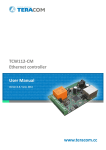
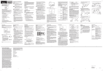
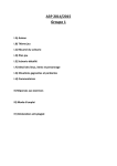
INSTALLATION, OPERATING and SERVICE MANUAL THE INSTALLATION OF THE UNIT SHALL BE IN ACCORDANCE WITH THE REGULATIONS OF THE AUTHORITIES HAVING JURISDICTION. SUPPLEMENTARY AND NPB CONTROL INSTRUCTIONS HEAD OFFICE MARKETING / PRODUCTION Newmac Mfg. Inc. DEBERT AIR INDUSTRIAL PARK, 208 LANCASTER CRESCENT P.O. BOX 9, DEBERT NOVA SCOTIA, BOM 1G0 PHONE: 902-662-3840 FAX: 902-662-2581 WAREHOUSE Newmac Mfg. Inc. 430 SPRINGBANK AVE., SOUTH WOODSTOCK, ONTARIO N4V 1B2 PHONE: 519-539-6147 FAX: 519-539-0048 EMAIL: [email protected] WEB SITE: newmacfurnaces.com NOTICE TO HOMEOWNER: READ AND SAVE THESE INSTRUCTIONS 156156 2210051 March 2013 Subject to change without notice Printed: HOMEOWNER INFORMATION Keep this manual so that it is accessible to technicians and future needs. Read this manual carefully before putting the pellet burner into service. Follow this manual and its instructions carefully and do the recommended management and maintenance. If you have any questions your Newmac dealer will be happy to answer them for you. DESCRIPTION The NPB is intended to be mounted through the fire door of Newmac wood burning furnaces and shall be fired by wood pellets. The enclosed auger feeds the fuel from a separate storage hopper. A two stage heat thermostat controls the burner via the first and second stage call for heat that starts and stops the burner automatically. The burner has an on/off power switch on the left side of the burner. A programmable relay system controls the feed rates and supervises the burner functionality. The pellets are ignited with a hot rod heater when there is a call for heat. The start procedure is fully automatic in several steps to provide a fast and almost smoke free ignition. The burner shuts down completely when the thermostat is satisfied, and after a short cooling phase, is ready for the next heat cycle. A self cleaning scrapper keeps the burning grate clean and free of debris for fast and easy start ups. The cleaning cycle can be set to clean prior to start up at intervals dependant on the pellet type. CONSTRUCTION The construction and choice of material are made with a long life time in mind. The firing zone of the burner is made of stainless high temperature steel grate and ¼” plate steel. The burner is a gravity fed burner in which the auger delivers pellets from the hopper to the top of the feed tube. PELLET BREAK In the lower part of the pellet chute there is a gate that works as a break and places the fuel in the proper place for ignition and combustion. SAFETY FUNCTIONS The NPB fulfills all existing safety requirements including: overheat protection on the feed tube that turns the burner off if the temperature reaches 170˚F photo cell that supervises the flame chute gate and feed tubes that provide burn back protection safety switch which will not allow the auger to run while the hopper lid is open flexible feed hose that melts off and prevents the pellets from entering the burner in case of burn back or overheating proximity sensor to prevent feed tube from plugging NPB LOCATION The NPB is mounted through the NPB fire door on Newmac wood burning furnaces and boiler. See Figures 1 and 2. ELECTRICAL CONNECTIONS The NPB model is connected through the existing 120 V draft fan control box, as well as the NPB thermostat being wired to ensure only one combustion type, oil or pellets, may fire at any given time. See Figures 3, 3a, 3b, 4, 4a, and 4b. THERMOSTAT The NPB model requires a two stage heat thermostat to control high and low burn rates. The Robertshaw RS2210C is a recommended and supplied thermostat. Refer to Figure 4, 4a, and 4b for thermostat connection. In case of power failure or the furnace limiting, the thermostat will default to a 68 degree F setting if without power and battery backup for more than 40 seconds. With battery backup, provided 2 AA batteries, the thermostat will maintain settings previous to power failure or limiting. 1 FAN & LIMIT CONTROL The NPB furnace model uses only the limit side of the fan & limit control. NPB CONTROL OPERATION AND FURNACE SET UP The NPB control operates on 24V DC. Refer to Figures 3, 3a, 3b, 3c, 4, 4a, and 4b. The High and Low feed rates are factory set. They can be field adjusted by a service technician to increase or decrease the feed rates to desired levels according to the furnace model or owners preference. See TABLES 4a & 4b for recommended settings. HEATING The feed rates are factory set but may require adjustments to attain desired temperature rise. The typical temperature rise should be 75°F, plus or minus 5°F. The unit is designed for a maximum temperature rise through the furnace of 85°F at a maximum external static pressure of 0.50 inches of water column. However, due to the wide range of static pressures in duct systems, it is the responsibility of the installer to verify that the temperature o rise does not exceed 85 F. To measure the actual temperature rise insert a thermometer and note the temperature of the warm air supply at a point at least 24 inches upstream from the heat exchanger surface and the temperature at the return air grill and take the difference. Air temperature rise can be lowered by increasing the blower speed, lowering the feed rate, or increasing undersized supply and return air free area. The furnace will not operate properly and its life will be decreased if insufficient air quantity passes over the heat exchanger. Similarly, too much air during heating mode resulting in a o temperature rise of less than 65 F may cause heat exchanger degradation due to condensation. FEED SYSTEM INSTALLATION Using the auger feed system and hopper assembly supplied insures that the feed system is installed in the correct position. See Figures 5, 6, and 7. For proper Hopper and Auger set-up see Figure 22. The feed auger and hopper are designed to maintain an auger angle of approximately 45 degrees. The flexible feed hose should be at least 12 inches in length. The auger should also be placed so that it sits a little to the side of the pellet chute of the burner. This will prevent pellets from entering the burner if burn back should occur and the feed hose burns off as part of safety. The start dose shall be approximately 40 seconds to maintain consistent and correct ignitions. This is factory set and may be adjusted by a technician if required. SET UP PROCEDURE Refer to Figures 1, 5, & 7 1. Remove existing fire door and frame from your furnace. 2. If installing on a CL series, insert the 6” stainless steel baffle by resting it on the side stabilizers and pushing it to the back of the firebox. See Figure 1 3. Attach the supplied heat shield to the front of the furnace. See Figure1 4. Mount the NPB fire door and frame on the Newmac wood burning furnace or boiler. 5. Make sure to put the gasket on the door before installing the burner. 6. The NPB will come as one unit already put together. 7. Mount the burner through the opening in the door and four bolts. 8. The burner can be held in place on the four bolts with the four nuts and washers provided. 9. The feed tube can be turned to the desired angle for the feed system to be connected. 10. The hopper lid switch needs to wired to the control as per Figure 4. 11. The cover needs to be attached before the power, feed system and thermostat can be hooked up to the control. 12. Once the cover is attached and power is on, the control should be manually tested. IMPORTANT: The feed auger should be run by itself until the pellets flow at a constant rate. This can be done by connecting the burner power cord directly into the auger motor power cord. This may take up to 20 minutes. 2 MANUALLY TESTING CONTROL Using the navigation keys, see Figure 8a, you can scroll through the six menus and manually adjust certain aspects of the burners program, such as the feed rates. Pressing button 1 (first from the left, left arrow) lets you scroll through the menus, while pressing button 2 (down arrow) reverses the direction of the scroll sequence. To adjust a setting such as the low feed rate, first scroll to the appropriate menu using button 1. To program you press the white button 6 (furthest to the right), together with button 4 (right arrow). The value available to be changed will flash. To change the desired value, use button 2 to decrease the value or button 3 (up arrow) to increase the value. To jump between different variables within the same menu you use button 4. The changed value can be saved by pressing the menu/ok (green) button 5. Refer to Tables 4a and 4b for factory settings. To manually test the control fan, you must simultaneously press and hold down buttons 1 & 2 for high speed and buttons 1 & 3 for low speed. To manually test the cleaning grate, you must simultaneously press and hold down buttons 4 & 2 for the forward direction and buttons 4 & 3 for the reverse direction. Always wait a couple seconds between changing directions to allow for the capacitor to lose its dwelling charge. IMPORTANT: While running in the forward direction, make sure not to run too far to cause binding of the motor. The cleaning grate should always be run in the reverse direction until the limit switch shuts it down prior to initial start up or subsequent testing when it has been manually run. FUEL PELLETS Pellet fuels are put into 3 categories in terms of ash content: Premium at 1% or less, Standard at 2% or less and all others at 2% or more. When using higher ash content pellets more frequent ash removal, scraping, and cleaning of burner may be required. Higher ash content pellet may also provide less Btu’s per pound. The Burner should normally burn 6 – 12 mm diameter fuel pellets, which come either in 40 lb. (16 kg) bags or are supplied by bulk delivery truck. If you have a bulk storage container you should follow the recommendations to ensure that the quality of the pellets does not deteriorate. Never use pellets which do not meet manufacturers’ recommendations. Damp pellets must never be used and should be disposed of immediately. The pellets can be made from different materials. The most common material is wood, but there are suitable alternatives on the market. The raw materials have different properties, which give them both advantages and disadvantages as a pellet fuel. The important factors are the energy value, the ash content, the volatile matter content, the environmental impact and price. The majority of the disruptions that can arise due to poor fuel quality are the results of poor production, handling and intermediate storage before the fuel reaches the end user. With high levels of fine chips, the deficiency is caused by the manufacturing process and by separation during storage at the loading site. The occurrence of sintering in the ash is due to silicate impurities and cannot be ascertained prior to combustion. Damp pellets may arise in connection with intermediate handling and transport. If possible, check when you purchase the pellets that they are clean, dry and have not broken down into small particles or chips. Damp pellets must be disposed of immediately. APPROVED FUEL SPECIFICATIONS Fuel Density 47 -58 lb/ft³ (600 750 kg/m³) Energy Content 7600 – 8700 Btu/lb (4.9 – 5.6 kWh/kg) Size/Diameter ¼” – ½” (6 – 12 mm) Size/Length max. 1 – 3/8” (35 mm) Moisture Content max. 12% Ash Content/Weight0.5 – 2% Fines Content/Weightmax. 3% Ash Melting Temperaturemin. 2000˚F (1100˚C) 3 MAINTENANCE NOTE: The main power must be turned off and disconnected before servicing the burner. The burner should be inspected weekly and cleaned appropriately when needed. The cleaning will be dependant on the amount of usage and pellet type being used. Have a qualified technician check the complete burner operation at least once a year. Cleaning of the heat exchanger, flue pipe, chimney and draft inducer if used, is especially important at the end of the heating season to minimize corrosion during the summer months caused by accumulated ash. CLEANING For best performance keep the burner and furnace clean. CAUTION – Be careful of hot parts on the burner and furnace! Hot ash can reignite when collected. Dispose of the ash outside in a covered metal container. Disconnect the power supply to the pellet burner. Make sure that the burner has shut down and cooled off for at least one hour. This will make it a cooler place to work and there will be no residual pellets burning in the pot to create smoke during the cleaning operation. Remove the flexible feed hose for ease of opening the fire door and getting into the firebox. Open the fire door to allow scraping of the grate. With the provided scraper, scrape all remaining ash from the back of the grate off the front into a metal container. Remove the pellet grate and scrape any remaining debris off into a metal container. With a suitable vacuum, vacuum out all ash from inside the burner which may have falling through the grate. Using the provided scraper or brush, scrape down all the firebox surfaces. A proper vacuum may also be used. Remove the ash from the firebox using provided shovel, or proper vacuum, by putting it into a metal container. Replace the baffle and pellet grate and close the fire door. Once the feed tube is put back in place the power may be connected and the burner checked for proper operation. Depending on the grade of pellet, this procedure may require more or less frequency. Establish a routine and follow it. ASH REMOVAL A good quality pellet has no more than 0.5% ash content. As a result the ash will need to be emptied at 3 to 4 week intervals depending on usage. Pellets with higher ash content will require the ash to be emptied more frequently. Shut the burner down using the thermostat and wait for the burner to complete it’s cool down cycle. Wait at least another hour for the burner and surrounding surfaces to cool down. Ashes should be placed in a metal container with a lid. The closed container of ashes should be placed on a noncombustible floor or on the ground, well away from all combustible materials, pending final disposal. If the ashes are disposed of by burial in soil or otherwise locally dispersed, they should be retained in the closed container until all cinders have thoroughly cooled. NOTE: Ashes usually contain live dormant coals, which may burn for many hours after a recognizable flame has disappeared. Use extreme caution when handling and disposing ashes. No other waste shall be placed in this container. 4 HOMEOWNER CHECKLIST Keep area around pellet burner clean and clear of combustibles. Use only dry wood pellets. DO NOT burn garbage, gasoline, oil, or any other combustible liquids. Remove ashes as directed. Watch for soot in smoke pipe, clean regularly. Clean furnace heat exchanger regularly. Always observe the minimum clearances to combustible materials. See the furnace service manual. Do not store solid fuel within the allowable clearances or within the space required for ash removal. Establish a routine for storage of fuel and care of the appliance. Figure 1 – Newmac CL 86-96 with NPB Figure 2 – NPB Fire Door 5 Figure 3 – NPB Wiring Diagram for CL Series Furnaces Wiring diagram explained: 1. 2. 3. 4. 5. DISCONNECT ALL POWER TO THE FURNACE BEFORE PROCEEDING disconnect and remove draft fan connect the supplied power cord wires, part # 2200114, to the wires in the draft fan “J” Box, and ground unhook both black wires from the Honeywell # R8225B Relay connect the two black wires from the # R8225B Relay to the two middle wires (supplied) from the NPB terminal block Refer to Figure 4 6. connect the black wire from the draft fan “J” Box to the black wire from the Interlock Control (White-Rogers 8A05A-4) 6 Figure 3a – NPB Wiring Diagram for WB Series Furnaces Wiring diagram explained: 1. 2. 3. 4. DISCONNECT ALL POWER TO THE FURNACE BEFORE PROCEEDING disconnect and remove draft fan connect the supplied power cord wires, part # 2200114, to where the draft fan wires were connected connect the supplied jumper across the wood thermostat connector 7 Figure 3b – NPB Wiring Diagram for WAO Series 8 Figure 3c – NPB Wiring Diagram for BC-160 Boiler 9 Figure 4 – NPB Control Wiring Figure 4a – NPB Thermostat Wiring (Robertshaw RS2210C) 10 Figure 4b – NPB Model Thermostat Wiring 11 Figure 5 – NPB System – General Assembly 12 Figure 6 – NPB Pellet Hopper 13 Figure 7 – Complete NPB System with CL Series CONTROL AND SETTINGS Figure 8 – Programmable Control TABLE 1 – CONTROL CONFIGURATION Element Retractable mounting feet. Screw terminal block for the power supply. LCD display, 4 lines, 18 characters. Screw terminal blocks for discrete/analog inputs. Relay output screw terminal block. Slot for backup memory or PC connection cable. Shift key Menu/OK key for selection and confirmation. Navigation keys or after configuring Z pushbuttons. Prompt 1 2 3 4 5 6 7 8 9 Figure 8a – Function Buttons TABLE 2 – FUNCTION BUTTONS 14 1 Button # 1, left arrow 2 Button # 2, down arrow 3 Button # 3, up arrow 4 Button # 4, right arrow 5 Button # 5, MENU/OK 6 Button # 6, Shift key Figure 9 – NPB Title Menu When you first turn on the power you will see this information on display. To scroll between menus press button 1 (left arrow). See Figure 8a. Figure 10 – NPB Running Status Menu two shows you the current photo cell reading, the initial start-up feed time, and how long the current ignition cycle is. From this menu, you can manually adjust the photo cell reading required to start the soft feed cycle. It is factory set between 25 and 35 above the “Photo Read” reading before the first call for heat. Figure 11 – NPB Cycle Count Menu three shows the cycle counts, the Start Feed setting, and the Clean Cycle setting. From this menu you can manually adjust the Start Feed setting which is factory set at 40 and recommended to keep it between 35 and 45. Depending on the grade of pellet the cleaning cycle should be between 1 and 5, lower for poorer grade pellets. 15 Figure 12 – NPB Low Fire Feed Rates Menu four shows the low fire feed rates, which are manually adjustable. The suggested feeds rates per model are shown in Tables 4a and 4b located at the back of this manual. Figure 13 – NPB High Fire Feed Rates Menu five shows the high fire feed rates, which are manually adjustable. The feed rates, low and high, will be factory set according to the furnace model. Figure 14 – NPB Overheat Fault Menu This Fault Menu will appear if the feed tube sensor reaches 170 F and will remain until the temperature drops 40 F and the Thermodisc is manually reset. The burner is inoperable while this menu appears on the control. 16 Figure 15 – NPB Fuel Fault Menu This Fault Menu will appear if a fuel fault occurs and will remain until the problem is resolved. Refer to Table 3 in the manual. Figure 16 – NPB Ignition Fault Menu This Fault Menu will appear when an ignition fault occurs and will remain until the problem is resolved. Refer to Table 3 in the manual. Figure 17 – NPB Hopper Lid Not Closed Fault Menu This Menu will appear if the hopper lid is not closed properly on the lid switch and the auger will not run. 17 Figure 18 – NPB Feed Tube Plugged Menu This Menu will appear if pellets build up the feed tube and cause the Proximity Sensor to go off. This will result in the pellet burner going in to shut down mode and will not restart till the photocell in satisfied there is no longer flame present. Figure 19 – NPB Cleaner Is Running Menu This Menu will appear whenever the cleaner is not fully back in position and the auger will not run. Figure 20 – NPB High Fire Running Menu This Menu will appear only when the NPB is in running mode and second stage heat is called for. 18 Figure 21 – NPB Low Fire Running Menu This Menu, like Fig 20, will appear only when the NPB is in running mode and only if first stage heat is called for. Figure 22 – NPB Hopper Chain Set-Up 19 TABLE 3 - FAULT DIAGNOSIS FAULT OVERHEAT FAULT IGNITION FAULT FUEL FAULT CAUSE 1. Feed tube sensor has opened due to temperatures of 170 F or more 2. Not enough draft 3. Feed rate too high ACTION 1. Let cool 2. Manually reset thermodisc 3. If flexible feed hose has melted, replace 4. May need to increase draft 5. Adjust feed rates 1. 2. 3. 4. Wrong start feed Broken ignition element Blocked feed chute Photo cell dirty or broken 1. 2. 3. 4. 5. Change start feed Replace igniter Clean out chute Clean or replace photo cell Make sure auger is feeding pellets 1. Pellet hopper is empty. 2. Auger and/or chute are blocked 3. too heavy a feed rate 4. photo cell dirty or broken 5. auger not running 1. 2. 3. 4. 5. Fill hopper with pellets Clean out blockage Clean or replace photo cell Adjust feed rate make sure auger is running properly The function of the included ash scraper is for cleaning off the pellet grate. NOTE: Never attempt to clean the pellet grate while burner is running or power is turned on! TABLE 4a – SUGGESTED FEED RATES PER MODEL FOR PREMIUM PELLETS MODEL High Burn – On High Burn – Off Low Burn – On Low Burn - Off CL 86-96 42 20 20 30 CLC 90-100E 42 20 20 30 WB-100 70 40 35 45 WFA-70 70 40 35 45 WAO 60 38 35 43 CL 115-170 90 20 35 35 BC-160 90 20 35 35 NOTE: Feed rates shown above are premium pellets (less than 1% ash) while below are standard pellets (greater than 1% but less than 2% ash). TABLE 4b – SUGGESTED FEED RATES PER MODEL FOR STANDARD PELLETS MODEL High Burn – On High Burn – Off Low Burn – On Low Burn - Off CL 86-96 40 30 20 40 CLC 90-100E 40 30 20 40 WB-100 60 35 35 60 WFA-70 60 35 35 60 WAO 50 52 25 50 CL 115-170 90 25 35 35 BC-160 90 25 35 35 NOTE: For the EPA models, the internal secondary air baffles must be removed for proper burner operation. NOTE: For a retrofit into a 7” flue, the included stack reducer should be installed if needed. CSA B415.1 TEST RESULTS Premium Pellets used are those with Ash content less than 1%, while the Standard Pellets used are those with Ash content less than 2% but greater than 1%. 20 WB-100 Results PREMIUM Date 25/8/11 24/8/11 24/8/11 23/8/11 Run # 4 3 2 1 Category high med-high med-low low STANDARD Date 31/8/11 30/8/11 30/8/11 29/8/11 Run # 4 3 2 1 Category high med-high med-low low Burn Rate Particulate Emissions Particulate Emissions (lbs./hr.) 14.67 10.17 7.96 6.16 g/h 2.04 1.93 1.82 1.16 g/MJ 0.02 0.03 0.03 0.03 Burn Rate Particulate Emissions Particulate Emissions (lbs./hr.) 17.58 10.9 8.79 6.81 g/h 2.93 2.07 1.64 1.37 g/MJ 0.02 0.03 0.03 0.03 direct output BTU 113,044 72,404 48,004 38,328 direct output BTU 130,815 73,300 60,307 42,324 direct CSA eff. % 76.2 73.0 64.0 66.1 eff. % 89.2 82.5 69.9 72.0 direct CSA eff. % 79.6 69.0 71.3 65.8 eff. % 94.8 77.9 79.5 72.0 direct CSA eff. % 78.3 68.3 66.9 61.2 eff. % 94.3 77.6 75.5 66.6 direct CSA eff. % 78.7 75.3 68.4 65.5 eff. % 94.3 85.4 75.8 71.5 direct CSA eff. % 77.4 72.0 66.5 61.8 eff. % 91.9 81.7 73.6 67.3 direct CSA eff. % 82.4 78.8 71.1 65.0 eff. % 100.7 92.1 80.9 71.7 CL 86-96 RESULTS PREMIUM Date 11/7/2011 12/7/2011 13/7/2011 17/8/2011 Run # 4 3 2 1 Category high med-high med-low low STANDARD Date 28/6/2011 29/6/2011 30/6/2011 14/7/2011 Run # 4 3 2 1 Category high med-high med-low low Burn Rate Particulate Emissions Particulate Emissions (lbs./hr.) 14.57 9.75 8.65 6.39 g/h 2.21 2.02 1.75 0.81 g/MJ 0.02 0.03 0.03 0.02 Burn Rate Particulate Emissions Particulate Emissions (lbs./hr.) 13.96 10.3 8.74 7.31 g/h 2.86 2.84 1.81 1.35 g/MJ 0.03 0.04 0.03 0.03 direct output BTU 118,603 65,359 56,408 36,769 direct output BTU 113,674 75,967 57,222 45,182 WAO RESULTS PREMIUM Date 26/7/11 27/7/11 27/7/11 28/7/11 Run # 4 3 2 1 Category high med-high med-low low STANDARD Date 19/7/11 21/7/11 21/7/11 22/7/11 Run # 4 3 2 1 Category high med-high med-low low Burn Rate Particulate Emissions Particulate Emissions (lbs./hr.) 13.96 8.93 6.77 6.39 g/h 1.76 2.1 1.16 1.52 g/MJ 0.02 0.04 0.03 0.04 Burn Rate Particulate Emissions Particulate Emissions (lbs./hr.) 14.76 10.39 7.99 6.06 g/h 3.92 2.12 1.04 0.078 g/MJ 0.06 0.03 0.04 0.02 21 direct output BTU 105,263 59,843 40,906 35,309 direct output BTU 121,977 78,547 53,050 35,666 TABLE 5 – NPB PARTS LIST 4110239 4120526 4120532 5300019 FIREDOOR ASSEMBLY FIREDOOR HEAT SHIELD FIREDOOR FRAME FIREDOOR HANDLE COMPLETE 4120517 4120518 AUGER COVER BURNER COVER 2080113 2080114 2080115 2080116 BURNER GASKET FEED TUBE GASKET LEFT SIDE COVER GASKET FIREDOOR GASKET 2020040 4060441 4120520 4080166 1150056 2190100 AUGER MOTOR AUGER WELDED AUGER ASSEMBLY AUGER COLLAR AUGER TUBE FLEXIBLE FEED HOSE 3130022 4120527 4120538 BAFFLE - CL CL HEAT SHIELD WB HEAT SHIELD 4080150 BURNER ASSEMBLY 4080159 4080160 4080161 4060443 CLEAN PLATE CLEANING ASSEMBLY CLEAN ATTACHMENT GRATE 2020041 2040003 2090089 2010097 4160212 2180020 2010056 2010100 2090088 LINEAR GEAR MOTOR COMBUSTION FAN IGNITER THERMOSTAT PHOTOCELL ASSEMBLY POWER ENTRY FILTER CAPACITOR POWER SUPPLY NPB CONTROL 2210051 MANUAL 4120529 4120530 4120519 2090087 2010101 BURNER SCRAPER BOX SIDE COVER HOPPER FEED ASSEMBLY PROXIMITY SENSOR RELAY 22 NEWMAC PELLET BURNER LIMITED WARRANTY Newmac Mfg. Inc extends the following limited warranty for Newmac Pellet Burners. Subject to the conditions, exclusions and limitations set forth below, Newmac warrants to the original owner of the Pellet Burner that it will operate free from defects in material and workmanship under normal conditions and use, as described in the operating instructions supplied with the pellet burner, during the warranty period described below. Newmac Mfg. Inc. will, at its option, repair or replace any product covered by this warranty that is determined to be defective in material or workmanship. Period: The warranty period begins on the date of original installation. 1. Burner components warranted for five (5) years include the burner box, stainless steel burner body, steel feed tube, hopper, auger tube. 2. Mechanical components which are warranted for three (3) years include the: auger shaft, shaft bearing, shaft coupler, cleaning scraper, and grate 3. Electrical components that are warranted for two (2) years include the: control, relay, blower, auger motor, power supply, cleaning motor, igniter, switches, thermo disc and photocell. Conditions: This warranty applies only to the Newmac Pellet Burners which: 1. are installed, operated, and maintained as recommended in the Newmac Pellet burner user’s manual. 2. remain at the site of original installation. 3. have not had any unauthorized alterations after leaving the factory. 4. the registration form has been completed and returned to Newmac Mfg. Inc. within 30 days from date of purchase. Exclusions: This warranty does not cover the following: 1. consumable and normal wear items, including, without limitation, gaskets, paint, flexible feed tube, baffles. 2. damage resulting from: a. failure to install, operate or maintain the pellet burner according to the installation and operating instructions and labels furnished with the pellet burner; b. failure to install the pellet burner according to local building codes; c. shipping or improper handling; d. abuse, misuse, continued operation with damaged, corroded or failed components, accident, or incorrectly performed repairs; e. over-firing; f. corrosion; g. environmental conditions, inadequate ventilation, negative pressure or drafting caused by tightly sealed construction, insufficient make-up air supply, or handling devices such as exhaust fans or forced air furnaces or other such causes; h. use of fuels other than those specified in the operating instructions; i. installation or use of components or accessories not supplied with the pellet burner or authorized and approved in writing by Newmac Mfg. inc; j. modification of the product not expressly authorized and approved by Newmac Mfg. Inc. in writing; k. interruptions or fluctuations of electrical power supply to the pellet burner; 3. noise caused by minor expansion, contraction or movement of parts; 4. the pellet burners capability to heat a desired space; information is provided to assist the consumer and the dealer in selecting the proper product for the application; consideration must be given to product location and configuration, environmental conditions, insulation and air tightness of the structure; 5. additional or unusual utility bills incurred due to any malfunction or defect in the pellet burner. 6. labour charges, travel costs, transportation or delivery costs involved with the repair or replacement of defective component parts. Claim or service procedure: Contact the dealer who sold you the product. If that dealer cannot provide the warranty or service, contact the distributor that they purchased the product from to find an alternate dealer and proceed with service or warranty. Claims must be made within the warranty period. Travel and shipping charges for parts are not covered by this warranty. Limitations of Liability: Repair or replacement in accordance with the provisions of this warranty will be the owner’s exclusive remedy for and will constitute Newmac Mfg. Inc. sole obligation under this warranty, under any other warranty (express or implied), or in contract, tort or otherwise. No employee, agent, dealer, or other person is authorized to give any warranty on behalf of Newmac Mfg. Inc. TO THE EXTENT ALLOWED BY LAW, NEWMAC MFG. INC. MAKES NO OTHER WARRANTY, EXPRESS OR IMPLIED, INCLUDING ANY WARRANTY OF MERCHANTABILITY OR FITNESS FOR A PARTICULAR PURPOSE. NEWMAC SHALL NOT BE LIABLE FOR ANY CONSEQUENTIAL OR INCIDENTAL DAMAGES HOWEVER CAUSED WHETEHER BY DEFECT IN THE PELLET BURNER OR ANY PART THEREOF WARRANTED HERE UNDER OR BY THE NEGLIGENCE OF ANY PERSON. Some states and provinces do not allow exclusions or limitation of incidental or consequential damages, so these limitations may not apply to you. This warranty gives you specific rights; you also may have other rights, which vary from state to state or province to province. The duration of any implied warranty is limited to the duration of the warranty period specified herein. 23 INSTALLER/RETAILER INFORMATION NAME:_______________________________COMPANY______________________________ Signature of the Installer:______________________________________________________ The homeowner should telephone (___)________________for a service call or for additional information. APPLIANCE INITIAL TEST AND SERVICE INFORMATION MODEL:__________________________________INSTALLATION DATE:____________________ FURNACE SERIAL NUMBER_________________________________________________________ PELLET BURNER SERIAL NUMBER__________________________________________________ PELLET BURNER SETTINGS AS TESTED Set Photocell Reading :________________ Start-up Feed Time (sec.) :________________ Ignition Time (sec.) :________________ Clean Cycle setting :________________ Low Fire Rate settings – Auger On time (sec.) :__________ Auger Off time (sec.) :__________ High Fire Rate settings - Auger On time (sec.) :__________ Auger Off time (sec.) :__________ Start Feed setting (sec.) :_________________ Flue Draft (“WC):________________________ 02% :________________________________ Flue Gas Temp :________________________ C02%:________________________________ Burner Feed Rate (high/low):_______________ Temperature Rise:_______________________ CUSTOMER INFORMATION Name:_______________________________________________________________________ Address:____________________________________________________________________ Postal Code:_______________________________________________________________________ City:________________________________________________________________________ Phone:______________________________________________________________________ Date:________________________________________________________________________ 24