1
INSTALLATION
DRIVING LIGHTS for FLHT/FLHX/FLHR — BLACK
THANK YOU FOR CHOOSING KϋRYAKYN!
PROTECT YOURSELF AND OTHERS FROM POSSIBLE INJURY AND PROPERTY
DAMAGE OR LOSS. PAY CLOSE ATTENTION TO ALL INSTRUCTIONS, WARNINGS,
CAUTIONS, AND NOTICES REGARDING THE INSTALLATION, USE, AND CARE OF
THIS PRODUCT.
THIS INDICATION ALERTS YOU TO THE FACT THAT
IGNORING THE CONTENTS DESCRIBED HEREIN CAN
RESULT IN POTENTIAL DEATH OR SERIOUS INJURY.
This indication alerts you to the fact that ignoring the
contents described herein may negatively affect product
performance and functionality or damage the product itself
or the product to which it is being attached.
MAKE SURE THE FOLLOWING PARTS HAVE BEEN INCLUDED IN THE KIT:
1
1
1
1
4
1
1
1
1
Right Driving Light Assembly
Left Driving Light Assembly
Right Driving Light Bracket
Left Driving Light Bracket
Driving Light Bracket Plugs
12-Pin Wiring Adapter
Hardware Kit including:
4
5/16”-18 Jam Nuts
4
5/16” Flat Washers
2
1/4”-20 x 3/4” Socket Head Cap Screws
2
1/4” Narrow Flat Washers
4
Driving Light Spacers
4
5/16”-18 x 1” Button Socket Cap Screws
4
5/16”-24 x 1” Button Socket Cap Screws — NOT USED
All Purpose Lighting Installation Kit including:
1
Dielectric Grease Pack
6
Female T-Tap Connectors
6
Male Spade Connectors
2
3-Pin Connectors — Black — NOT USED
2
4-Pin Connectors — Black
2
6-Pin Connectors — White
1
24” Power “Y” Wire Assembly (White)
12
6” Cable Ties
Installation Instructions
YOU WILL ALSO NEED:
Set of Hex Wrenches, Set of Torx Wrenches, Screwdrivers, Small Pick, Vise Grips, Set of Combination
Wrenches, Socket Set and Ratchet, Wire Stripper, Test Light or Multi-meter
These installation instructions contain important information.
Ensure that the end user receives this copy and is aware of its
importance for future reference.
STEP 1
Read and understand all steps in the instructions before starting the installation. Park
the motorcycle on a hard, level surface and turn IGN OFF. Put the bike on its center
stand (if equipped) or secure it in a motorcycle wheel chock. Remove the main fuse.
Avoid damage to the motorcycle. Protect painted surfaces with
a soft cloth or blanket.
5029-23HD-0315
-cont.-
5029
CUSTOMER SERVICE
877.370.3604 (toll free)
INSTALLATION QUESTIONS
[email protected]
or call 715.247.2983
LIMITED WARRANTY
Küryakyn warrants that any Küryakyn products
sold hereunder, shall be free of defects in
materials and workmanship for a period of one
(1) year from the date of purchase by the
consumer excepting the following provisions:
● Küryakyn shall have no obligation in the event
the customer is unable to provide a receipt
showing the date the customer purchased the
product(s).
●The product must be properly installed,
maintained and operated under
normal conditions.
●Küryakyn makes no warranty, expressed or
implied, with respect to any gold plated
products.
●Küryakyn shall not be liable for any
consequential and incidental damages, including
labor and paint, resulting from failure of a
Küryakyn product, failure to deliver, delay in
delivery, delivery in nonconforming condition, or
for any breech of contract or duty between
Küryakyn and a customer.
●Küryakyn products are often intended for use in
specific applications. Küryakyn makes no
warranty if a Küryakyn product is used in
applications other than intended.
●Küryakyn electrical products are warranted for
one (1) year from the date of purchase by the
consumer. L.E.D.’S contained in components of
Küryakyn products will be warranted for defects
in materials and workmanship for 3 years from
the date of purchase where as all other
components shall be warranted for one(1) year.
This includes, but is not limited to; control
modules, wiring, chrome & other components.
●Küryakyn makes no warranty of any kind in
regard to other manufacturer¹s products
distributed by Küryakyn. Küryakyn will pass on
all warranties made by the manufacturer and
where possible, will expedite the claim on behalf
of the customer, but ultimately, responsibility for
disposition of the warranty claim lies
with the manufacturer.
ABOUT OUR CATALOG
For purchasing Küryakyn® products, you
can receive a complete catalog free of charge.
Send the Proof-of-Purchase below with your
address to: Küryakyn
454 County Road V V
Somerset, WI 54025-9031
Please indicate either Accessories Catalog for
Harley-Davidson® or GL & Metric Cruisers.
Be sure to ask your local dealer about other
Küryakyn® products, the motorcycle parts and
accessories designed for riders by riders.
©2005 Küryakyn USA® All Rights reserved.
THE END USER’S SAFETY DEPENDS UPON PROPER INSTALLATION OF
THIS PRODUCT. IF A STEP IN THESE INSTRUCTIONS IS NOT WITHIN
YOUR CAPABILITIES OR YOU DO NOT HAVE THE CORRECT TOOLS,
HAVE YOUR DEALER PERFORM THE PROCEDURE. IMPIC 1
PROPER INSTALLATION OF THIS PRODUCT COULD RESULT IN DEATH OR SERIOUS INJURY.
TOP
ACCIDENTAL VEHICLE START-UP COULD CAUSE
DEATH OR SERIOUS INJURY, REMOVE THE MAIN FUSE
BEFORE PROCEEDING.
DRIVING LIGHT ASSEMBLY:
STEP 2
Prepare a soft, sturdy work surface within arm’s reach of the motorcycle.
STEP 3
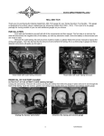
Refer to PIC 1. Locate the Left (clutch-side) and Right (brake-side) Driving Light
Brackets and Driving Light Assemblies in the kit.
STEP 4
Refer to PIC 2. Route the wiring from the Light Assemblies downward through the
curved slots in the Brackets.
STEP 5
Refer to PIC 3. Secure the Light Assembly to the Brackets with the included 1/4”20 x 3/4” Socket Head Cap Screws and 1/4” Narrow Flat Washers; leave the
screws snug to allow for adjustment later.
STEP 6
Route the wires down into the channel in the Light Bar as shown in PIC 4.
BRAKE-SIDE (RIGHT)
CLUTCH-SIDE (LEFT)
PIC 2
ROUTE
THE
WIRES
THROUGH
THE SLOT
BRAKE-SIDE (RIGHT)
PIC 3
BIKE PREP:
STEP 7
Follow the steps outlined in the model-specific service manual to remove the outer
fairing or headlight.
STEP 8
Separate the existing turn signal connectors:
BRAKE-SIDE (RIGHT)
SECURE THE
LIGHT ASSEMBLY TO THE
BRACKET WITH
A 1/4” SCREW
AND WASHER
‘06—Later Electra Glide and Street Glide refer to PIC 5 two (2) black 4-pin
connectors with three wires each.
‘05—Earlier Electra Glide and Street Glide and ‘97—’13 FLHR refer to PIC 6
one (1) black 6-pin connector with six wires.
PIC 4
The connector is typically found on the clutch-side (left) of Electra Glide and Street
Glide inner fairings and inside the headlight bucket on Road Kings.
‘14—Later FLHR refer to PIC 7 — one (1) black 4-pin connector with four wires
AND one (1) black 6-pin connector with four wires; they are located just forward
of the fuel tank on the clutch-side (left).
STEP 9
Road King models (Except ‘14—later FLHR) Separate the existing 2-Pin passing-lamp connectors (white connector with two grey wires).
Remove the existing light bar assembly from the motorcycle (note the existing
wire-routing for later); set the assembly aside, it will not be reused.
PIC 6
CLUTCH-SIDE (LEFT) OF FAIRING
PIC 7
BRAKE-SIDE (RIGHT)
PIC 5
TYPICAL LOCATION ON ‘06 AND
LATER (BRAKE-SIDE). CLUTCHSIDE IS SIMILAR
CLUTCH-SIDE (LEFT)
SEPARATE THE TURN SIGNAL CONNECTORS
INSTALL
-cont.-
TYPICAL LOCATION ON ‘05 AND
EARLIER MODELS
‘14-UP ROAD KING TURN SIGNAL CONNECTORS LOCATED JUST FORWARD OF THE
FUEL TANK ON THE LEFT SIDE
DRIVING
DRIVING LIGHTS for FLHT/FLHX/FLHR — BLACK
PAGE
2
INSTALLATION
LIGHTS:
STEP 10
Attach the Driving Light Assemblies to the motorcycle with the included fasteners:
FLHT and FLHX (Batwing fairing) models — use the included 5/16”-18 X 1” Button Socket Cap
Screws and 5/16” Flat Washers;
Road King models — use the included 5/16”-18 Jam Nuts and 5/16” Flat Washers; if the threaded
studs protrude out of the Mounting Bracket, install the included Spacers between the Bracket and
forks.
Adjust the Brackets so the fasteners are centered in the holes, then snug them for now.
STEP 11
Ensure that the Driving Light wiring is routed along the pre-existing path without getting pinched or
kinked.
Secure the wiring away from moving parts, pinch points, or extreme heat.
Kuryakyn will not provide warranty coverage on any electrical component that
fails due to pinched, crimped, broken, abraded, melted, or frayed wires.
FOLLOW THE GUIDELINES BELOW TO PREPARE THE INCLUDED CONNECTORS.
INSERT TERMINAL AS
SHOWN. IT WILL ONLY FIT
ONE WAY
PRESS CLASP DOWN AND
TABS BACK INTO PLACE
SECOND,
LIFT THE
CLASP UP
“CLICK”
FIRST, PRY
THE SIDE
TABS AWAY
GENTLY TUG THE WIRE TO ENSURE IT IS SECURED
THE FOLLOWING GUIDELINES ARE MODEL– AND YEAR-SPECIFIC PROCEDURES.
DETERMINE THE CORRECT PROCEDURE BEFORE ASSEMBLING ANY OF THE INCLUDED
ELECTRICAL CONNECTORS.
PIC 10
PIC 8
PIC 9
BLACK
BLACK
BLACK
VIOLET
VIOLET
VIOLET
BLUE
BLUE
BLUE
BLUE
VIOLET
‘06—Later Electra Glide and Street Glide — requires two (2) of the 4-Pin 3 wire connectors. Refer to PIC 8.
BLACK
‘05—Earlier Electra Glide and Street Glide and ‘97—’13 FLHR — require one (1) 6-Pin 6 wire connector. Refer to
PIC 10.
‘14—Later FLHR — requires one (1) 4-Pin 3 wire connector for the clutch-side (left) and one (1) 6-Pin 3 wire connector for the brake-side (right). Refer to PICs 8 and 9.
-cont.-
DRIVING LIGHTS for FLHT/FLHX/FLHR — BLACK
PAGE
3
INSTALLATION
STEP 12
Prepare the model-and year-specific connectors by following the guidelines on
PAGE 3.
Dielectric grease inhibits moisture and prevents corrosion. Kuryakyn recommends the use of the included dielectric grease on ALL electrical connections.
Apply dielectric grease directly to mating surfaces.
STEP 13
Connect the Driving Light Connectors to those on the motorcycle.
STEP 14
All models (Except 1997 models and ‘14—Later Road King) Locate the included 12-Pin Wiring
Adapter in the kit;
Locate and separate the existing 12-Pin connector on the motorcycle wiring harness; it is typically
located on the brake-side (right) fairing-support-bracket below the radio;
apply some of the included Dielectric Grease to the open ends of the connectors and connect the
Adapter inline.
STEP 15
Locate the included 24” Power “Y” Wire Assembly (White) in the kit; connect it to the Adapter.
Connect the “Y” ends to the Driving Light white wires (male spade connectors).
Reinstall the main fuse, turn IGN ON, flip the existing driving-light switch ON and ensure proper
function of both the turn signals and Driving Lights. SKIP TO STEP 17.
STEP 16
All 1997 models and ‘14—Later Road King Reinstall the main fuse. Use a test light or multi-meter
to confirm a “switched” 12V (15A) source in the existing wiring harness.
CRIMP T-TAP ONTO “SWITCHED” 12V WIRE
NOTE:
PIC 11
With the power off, crimp both of the included Female T-Taps onto the
“switched” 12V wire(s). See PIC 11.
INSERT WHITE WIRE INTO T-TAP
‘14—Later Road King models: Typically the GREY
wire in the existing connector is “switched” 12V.
Apply some of the included Dielectric Grease to the open ends of the connectors; connect both the
white wires to the T-Taps on the “switched” 12V wire. See PIC 11.
Secure the wiring away from moving parts, pinch points, or extreme
heat. Kuryakyn will not provide warranty coverage on any electrical
component that fails due to pinched, crimped, broken, abraded, melted,
or frayed wires.
STEP 17
Secure the wiring away from hazards with the included Cable Ties.
STEP 18
Ensuring that the screw heads remain centered in the holes, tighten the Bracket fasteners;
snap the four (4) included Driving Light Bracket Plugs into place over
the screw heads.
STEP 19
Refer to PIC 12. VERTICAL ADJUSTMENT: loosen the screw on the
inner side of the knuckle, adjust the light, then tighten the screw
STEP 20
Refer to PIC 12. HORIZONTAL ADJUSTMENT: loosen the screw on
the underside of the mounting bracket, adjust the light, then tighten the
screw
-cont.-
PIC 12
BRAKE-SIDE (RIGHT)
VERTICAL
ADJUSTMENT
HORIZONTAL
ADJUSTMENT
IT IS THE END USER’S RESPONSIBILITY TO
ENSURE THAT THE DRIVING LIGHTS HAVE
DRIVING LIGHT SHOWN REMOVED FROM BIKE FOR CLARITY
BEEN ADJUSTED IN A WAY THAT DOES NOT
PAGE
DISTRACT ONCOMMING DRIVERS. DISTRACTED DRIVING CAN RESULT IN LOSS OF CONTROL LEADING TO SERIOUS INJURY OR
DEATH
DRIVING LIGHTS for FLHT/FLHX/FLHR — BLACK
4
INSTALLATION
STEP 21
Reinstall the outer fairing or headlight according to the service manual.
STEP 22
Ensure that the installation of the Driving Lights does not interfere with the proper operation of
the motorcycle BEFORE riding.
BULB REPLACEMENT:
Do not handle the new bulb with bare hands. Oil from your fingers will remain on the bulb and create a
hot spot when lit, shortening the life of the bulb. Remove all oil and debris with an ammonia based
cleaner or alcohol before completing reassembly.
Refer to PIC 13. Remove the screw on the underside of the lamp housing; set it aside for now.
Refer to PIC 13. Rotate the light bezel counterclockwise then pull it straight out; set it aside for now.
Refer to PIC 14. Note the orientation of the notch in the rubber seal as it is removed from inside the light housing.
Refer to PIC 15. Remove the bulb, note the notch in the locating ring, and separate the two wire connectors.
Refer to PIC 14 and 15. Remove the four (4) screws from the backside of the bulb assembly; set them aside for
now.
Refer to PIC 16. Separate the rear cover from the bulb housing; note the rubber gasket.
Refer to PIC 17. Push the connector on the white wire through the grommet; separate the spring from the bulb
assembly; remove and discard the bulb with the white wire.
Reassembly is the reverse of disassembly; align the notches in the new bulb with the boss on the bulb housing.
HOUSING SHOWN REMOVED FROM BIKE FOR CLARITY. IT IS NOT NECESSARY TO REMOVE TO CHANGE BULB.
PIC 15
PIC 14
PIC 13
REMOVE SCREW
LOCATING RING NOTCH
DISCONNECT WIRES
PAGE
4
REMOVE FOUR (4) SCREWS
ROTATE COUNTERCLOCKWISE TO REMOVE
PIC 17
PIC 16
PIC 18
REMOVE BULB
FROM SPRING
ALIGN THE
NOTCHES ON REAS-
CAREFULLY SEPARATE.
NOTE THE RUBBER
GASKET.
PUSH CONNECTOR
THROUGH GROMMET
Ride On!
It is the end user’s responsibility to ensure that all of the fasteners
(including pre-assembled) are tightened before operation of the motorcycle.
Kuryakyn will not provide warranty coverage on products or components
lost or damaged due to improper installation or lack of maintenance. Periodic inspection and maintenance are required on all fasteners.
DRIVING LIGHTS for FLHT/FLHX/FLHR — BLACK
PAGE
5
INSTALLATION