1
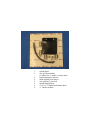
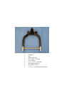
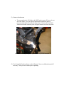
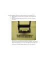
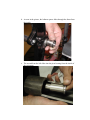
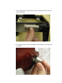
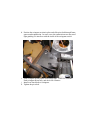
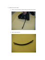
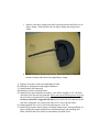
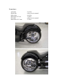
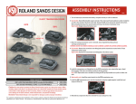
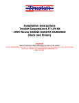
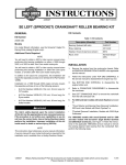
Instructions for 300 Phantom Swing Arm Kit for 2000 and up Softail or Deuce
Notes on fitting wide wheel and tire
• An advanced degree of mechanical skill is required to properly install this kit. If
after reading these instructions you have any doubts, we strongly recommend that
you have a professional install it for you. If you install the kit yourself, we
recommend that you also use the applicable shop manual for your
motorcycle. This kit involves significant alterations of your motorcycle and may
void your factory warranty.
• Whenever installing wheels and tires that are wider than original equipment,
please ensure that there will be sufficient clearance throughout the suspension
range in the frame, swingarm, fender, and fender struts, and that there is no
interference with the belt, belt guard, brake caliper, or exhaust system.
• Motorcycles can be dangerous if not properly maintained and ridden safely. RC
Components has no control over the usage of any of its parts. RC Components
expects its customers to exercise good judgment as to the proper selection,
installation, use, and maintenance of any parts. RC Components assumes no
responsibility for damage or injury of any kind because of the misuse or improper
application of any parts in any way by any person. RC Components expects the
end user to exercise good judgment.
• Before installing this kit, read through these directions completely. This will
familiarize you with the way in which the parts fit together and the tools needed
to complete the job.
• Before performing any installation steps, disconnect the motorcycle’s battery to
eliminate any possibility of electrical damage or personal injury due to a short
circuit.
Reference: Part Number INSTHD005
1
1
2
2
2
2
4
2
splash shield
new oil line assembly
(1 rubber line, 3 clamps, 1 plastic tube)
long stepped pivot spacers
short stepped pivot spacers
axle spacers (1 grooved)
splash shield spacers
¼-20 x 1/2” button head chrome bolts
¼” chrome washers
1
1
1
2
2
2
2
2
2
swingarm
axle
rubber bump stop
5/16”-18 x 1-1/4” bolts
5/16”-18 nuts
1/2”-13 x 1-1/4” axle bolts
axle washer-adjusters
axle adjuster covers
¼”-20 x ¾” socket head chrome bolts
Recommended Tools
This is a complex installation and will require several specialized tools to complete
correctly.
1. Sawzall – can substitute hacksaw or cutoff wheel.
2. 4-1/2” grinder.
3. Transmission pulley tool.
4. Main shaft locknut wrench.
5. Torque wrench
6. Shop supplies, (loctite-red and blue, anti-seize, etc.)
7. Replacement gaskets.
8. Bike specific service manual. (Refer to manual for all torque specs that
are not specified by RC Components.)
A) Stock component removal
To install the kit, it will be necessary to raise the motorcycle off the ground on a
suitable lift. WARNING – Be sure to center the motorcycle on the lift so that it
does not fall over when you raise it up or when you are working on it.
Installation of the kit begins with the disassembly and removal of the rear end of
the bike. Start with the simplest and most obvious components. For detailed
information on removal of these parts, consult your factory manual.
Disconnect the battery; drain the oil from the motor, transmission, and primary.
Remove:
1) Seat
2) Battery
3) Exhaust Pipes and mounting brackets
4) Fender strut covers, Fender, tail light and turn signals.
5) Rear wheel and rear brake.
6) Electronics from under seat and rear of oil tank.
7) Oil Tank
B) The next stage involves the removal of the inner and outer primary. Please
consult your factory manual for more detailed information.
1)
2)
3)
4)
5)
6)
7)
8)
9)
Begin by removing the outer primary cover.
Remove center nut from chain tensioner.
Remove retaining ring and release plate from clutch.
Remove clutch hub main shaft nut. NOTE: Left hand threads!!!
Remove compensating sprocket nut, spacer, sprocket cover and sliding
cam.
Remove clutch assembly, primary chain tensioner and sprocket as a single
assembly.
Remove starter jackshaft. Inspect primary case/jackshaft oil seal and
replace if necessary.
Remove starter motor from primary case.
Remove inner primary.
C) Remove stock swingarm.
1) Remove rear shock absorber bolts from swingarm.
2) Remove pivot shaft and spacers. Save pivot shaft and bearings as they
will be reused with the new swingarm.
3) Remove swingarm from frame.
D) Remove stock transmission; install new right side drive transmission.
For detailed information on removal and installation of transmission, consult
your factory manual.
E) Reinstall Primary. Please consult your factory manual for more detailed
information.
a. Install supplied locating dowel (tranny to primary) into primary with red
loctite.
b. Coat all seal lips with oil.
c. Mount inner primary. Do not tighten screws until starter is mounted.
d. Install starter shaft extension onto starter.
e. Install starter motor.
f. Torque all inner primary case bolts and starter motor bolts down to factory
specs and bend up the lock tabs.
g. Install jackshaft assembly. See factory manual for detailed breakdown of
jackshaft assembly. Torque jackshaft bolt and bend up locktab.
h. Install primary chain/sprocket/clutch assembly to motor and trans.
i. Install clutch pushrod inside mainshaft and install release plate, retainer
ring, adjuster screw, and jam nut. Adjust clutch to factory specifications.
j. Adjust primary chain to factory specifications.
F) Remove fender struts
a. To accommodate the 300 fender, the OEM fender struts will have to be cut
off of the frame. Cover all exposed motor and transmission parts to
prevent contamination from metal chips or dust. Remove the strut flush
with the horizontal connector plate and grind smooth as shown in picture:
b. We recommend painting the exposed metal to prevent corrosion.
G) Test fit supplied fender to frame to check fitment. Remove additional material if
necessary. Always test fit fender prior to painting.
H) Install swingarm. (When left or right is referred to, it’s as sitting on bike.)
a. Install bearings into front section of swingarm. (Insert bearings from
outside.)
b. Install spacers, inner and outer on each side. (See below for proper
placement.)
c. Notice there are two stepped spacers, and two short spacers. The
following pictures show there placement during assembly. Note that the
longest of the stepped spacers is used on the right side of the tranny, and
the short spacer with the thinnest shoulder is also on the right side.
d. As seen in the picture, the leftmost spacer slides through the frame from
the inside.
e. The second from the left slides into the pivot bearing from the inside of
the swingarm.
f. The second from the right fits between the transmission and the inside of
the pivot bearing.
g. The right most spacer slides through the frame and the pivot bearing from
the outside.
h. Position the swingarm section in place and slide pivot bolt through frame,
spacers and transmission. In some cases, the transmission case may need
light grinding if it interferes with the inside of the swingarm section.
i. Push swingarm upward until it hits bump stops. Check for clearance.
Push swingarm down fully, and check for clearance.
j. Install rear shock bolts to swingarm.
k. Tighten the pivot bolt.
I) Install oil line and oil tank
a. Remove stock oil drain line. Retain 90 degree fitting at the oil tank.
b. Install replacement line.
c. Remove extra hose clamp from end of replacement line and slide over 90
degree fitting. Slide hard line into 90 degree fitting and snug up hose
clamp.
d. Install oil tank per factory instructions. Route drain line to fitting on
bottom of frame and fasten with supplied hose clamp.
J) Replace electronics under seat and behind oil tank.
K) Install new splash guard with supplied hardware.
L) Install battery (disconnected)
M) Install previously test-fitted fender.
N) Install wheel, rotor and pulley assembly. Axle will be roughly an 1/8” shy from
each side of the flat area on swingarm. Drive side spacer has the groove on it, run
the axle bolts in by hand till they stop, adjust belt using the adjuster bolts, (Refer
to factory manual for suggested belt specs.) lock down the axle adjusters in the
end of the swingarm, now torque axle bolts to 65 ft. lbs. with red loctite.
O) Install supplied axle covers, use loctite and torque to 15 ft. lbs.
P) Install all previously removed parts, including exhaust Pipes, chosen taillight, etc.
Inspect all hardware and wiring before connecting battery and installing seat.
Check all fluids and fill to factory or aftermarket specified levels.
Torque Specs
Axle bolts
Shock bolts
Pulley bolts
Rotor bolts 3/8” rear
Pivot bolt
Rotor bolts 5/16” front
65 ft. lbs.
refer to service manual
60 ft. lbs.
30 ft lbs.
refer to service manual
25 ft lbs.
Test at slow speeds; take several short test rides before taking a road-trip. Visually
inspect before and after road testing. All components have been installed and
thoroughly tested. If proper assembly methods are used there will be no problems
with the use, function, and dependability of your bike. Now it’s time to get out and
show off your new ride. Be safe, have fun, and
RIDE ON.
If you have any questions concerning the installation of this kit please call
(270) 842-6000
or email [email protected]