1
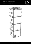
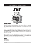
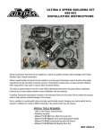
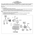
b aker S BD ™ in stall ation instr uction s
V1-122706
tm
FEATURES OVERVIEW
Stainless Steel pulleys for lifetime durability
Big 14mm tooth belt; compared to 8mm industry standard
Proprietary 2.4 “ wide belt carries over the ‘slammed in’ look of the O.E. Balance Drive
Outside bearing support with oversized radial ball bearings
12 plate clutch with 1.5X torque capacity and reduced clutch effort
80% reduction in low speed clutch rattle, compared to industry standard
FITMENT:
P/N 250-BTD; Big Dog, 2005-up with 250 size rear tire (1/2” offset powertrain)
P/N 300-BTD; Big Dog, 2005-up with 300 size rear tire (zero offset powertrain)
No additional hardware is required to complete the BAKER Synchronous Drive installation.
Blue and red loctite will be required for the installation.
The transmission fluid may have to be topped off after the installation. However, it’s a good idea to go
ahead and change the fluid if it has not been done recently.
PAGE | OVERVIEW
b aker S BD ™ include d part s
The following parts are included as shown in Figure 1:
Item
Description
A
Motor plate with transmission spacer plate
B
Starter pinion cover with fasteners
C
Outside bearing support with bearings, spindles, and pulley covers installed
D
Outside support “Position Jacks”
E
Clutch assembly with 43 tooth pulley
F
Throw out bearing assembly with retaining ring
G
Motor pulley (28 tooth)
H
BAKER Belt
A
G
F
D
H
C
B
PAGE | INCLUDED PARTS
E
b aker S BD ™ include d part s
The following parts are included as shown in Figure 2:
FIGURE
Description
2
Motor plate with transmission spacer plate
3
Outside bearing support w/ bearings, spindles, & pulley covers
4
Clutch assembly with 43 tooth pulley
FIGURE 2
FIGURE 3
FIGURE 4
PAGE | INCLUDED PARTS
b a ker S BD ™ S KILL S, KNOWLEDGE & TOOL S:
Special tools
No special tools are required to complete the installation. However the following common mechanic’s tools are
necessary to do the job in addition to standard every guy tools. (Figure 5).
Torque wrench
½” impact gun (pneumatic or electric)
13/16 and 15/16 sockets
Plastic or rubber mallet
Reference materials
A 2005-up Big Dog Service manual should be referred to for removal of the stock wet primary.
FIGURE 5
PAGE 4 | SKILLS, KNOWLEDGE, & TOOLS
b aker S BD ™ preparation
Please refer to the 2005-up Big Dog service manual for disassembly and removal of the stock primary drive. The short
version of the disassembly process goes as follows:
Disconnect the battery. Remember: ground cable first; use a 10mm wrench
Shut off the fuel at the tank petcock
Drain the primary oil. Remove the drain plug with a 3/16” allen.
Remove the clutch adjust access cover on the drive pulley cover on the right side of the bike. The access cover comes
off by hand, like an oil filter. Loosen the clutch rod jam nut and draw the pushrod out an inch or so.
Remove the following parts from the primary roughly in the following order:
•
Starter; 9/16 hex for battery feed and 2X3/8-16 with 5/16 allen for flange. It is not necessary to remove the starter
from behind the transmission. Let starter lay on back of transmission case during O.E. primary removal and belt
drive installation.
•
Outer primary; 14X1/4-20 cap screws, 3/16” allen
•Motor sprocket nut; 1-5/16 socket with impact. Set nut and washer aside. It will be re-used on the belt drive motor
pulley
•
Chain adjustment shoe nut; 9/16” socket
•
Remove throwout bearing on clutch with medium size snap ring pliers
•
Remove clutch nut with 1-3/16” socket and ½” impact gun. NOTE: lefthand threads, clockwise to loosen
•
Remove clutch, motor sprocket, and chain as a complete assembly (Figure 6)
FIGURE 6
PAGE | PREPARATION
b a k e r s b d ™ kit p reparation
•
Remove the 8X5/16-18 hex bolts from the inner primary. Bend back locktab wings and use a ½” socket to remove
bolts.
•
Remove the 2X5/16-18 cap screws from the outside front of the primary with a ¼” allen
Now, the real prep work begins for installation of the belt drive.
•
Loosen (just a couple turns) the six bolts that hold the transmission to the frame with an 5/8 wrench so the
transmission is free to move and align with the new belt drive motor plate.
•
Remove the primary o-ring from the engine case (Figure 7) so any water that enters that area can drain out.
FIGURE 7
•
Remove the six small o-rings from the transmission case, not required.
•
Leave the one o-ring on the snout of the transmission to help center the motor plate during installation
•
Remove Synchronous belt drive content from shipping box. Remove all six flat head screws from both pulley
covers. Outside bearing support assembly, motor sprocket, and clutch assembly will be separate.
•
Clean and degrease the motor and transmission areas.
PAGE | preparation
b a k e r sb d ™ install ation
Motor plate assembly Installation
Install the motor plate assembly onto the engine and transmission (figure 8) and loosely tighten the 5X5/16-18 cap
screws and 5X5/16-18 hex bolts on the motor and transmission with red loctite using a ¼” allen/1/2” socket. Note, the
stainless steel cap screws go on the engine. No beer breaks here because the red loctite will set up. The 6X7/16-14
hex bolts on the bottom of the transmission can be tightened down now with a 5/8 wrench. Lastly, torque all of the
5X5/16-18 cap screws and 5X5/16-18 hex bolts to 18 ft-lbs with a ¼” allen/1/2 socket. The motor plate installation is
complete. This tightening ritual/procedure is required because the Big Dog system relies on the snout of the transmission to orient the complete drivetrain and no shims under the transmission are required.
Install the new clutch assembly to the transmission mainshaft the LH clutch nut and washer provided. Using red
loctite, torque the nut to 80 ft-lbs.
FIGURE 8
PAGE | assembly
b a k e r sb d ™ install ation
Install the front motor pulley and lightly tighten the nut. Using a straight edge along the outside face of the pulley and
a pair of calipers, check to see that the two pulleys are axially located within .030” of each other. Use the motor plate
as a zero reference for measuring the pulley locations. (figure 9)
FIGURE 9
Motor sprocket shaft shims are supplied with the kit. Select the appropriate shim or shims. Once the axial pulley location is confirmed, remove the motor pulley nut and torque it to 150 ft-lbs with red loctite.
FIGURE 10
On a bench, screw the outer bearing support standoffs and
locking nuts as far into the outer support as they will go with
blue loctite (figure 10).
Temporarily install the outer support to the pulleys with 3
flathead screws in each pulley. Extend (loosen) the stand offs
until they lightly seat into the motor plate. The standoff height
is set. Remove the outer support from the pulleys.
PAGE | installation
b a k e r sb d ™ install ation
Install the starter pinion cover with
blue loctite on the three flat head
screws and torque them to
100 in-lbs (figure 11).
FIGURE 11
Install the clutch throwout bearing
assembly with the snap ring provided.
Adjust the clutch pushrod from the
right side. Lightly screw in the clutch
rod with a 7/32 allen until it stops and
back it out 1/3 turn. Set the 7/16-20
jam nut and reinstall the clutch adjust
cover. Test for clutch actuation and
feel. If there is excessive or no freeplay at the clutch lever, make appropriate adjustments at the clutch cable
adjuster.
Install the belt over the pulleys. Slowly
work it over the two pulleys and move
it inboard with a top to bottom rocking
motion. Use a rubber or plastic mallet
to help it on if necessary. If it does not go on even with persuasion from the mallet, call BAKER tech department. Do
not force it on. Make sure the belt is inboard of the outer pulley surfaces.
Install the outer bearing support to the motor pulley and lightly install the six attaching screws. If the clutch outer
bearing support cover will not readily slip into the clutch pulley, then start two screws at the bottom and gently pull the
bottom of the cover into the clutch pulley.
If the clutch cover still does not want to slip in the clutch pulley, then the spark plugs from the engine should be removed to allow the clutch to be rotated to walk the pulley cover on just like walking a chain onto a bicycle sprocket.
With both pulley covers in place, install all six flat head screws in each pulley with blue loctite and torque them to 100
in-lbs.
With the bearing support firmly attached to the pulleys, install the two long flat head screws through the stand offs
and into the motor plate with 100 in-lbs of torque and blue loctite. Some oil may be lost from the transmission mainshaft area (you will see it when the original clutch comes off) so be sure to recheck the oil level or better yet, change
the oil in your BAKER transmission at this time.
Reinstall the starter, connect the battery and take it for a test drive. If you have any questions or concerns, call
BAKER tech department.
PAGE | installation
ter ms
SPECIAL ORDERS
A minimum $500 deposit is required with all special orders. Special orders include unique case finishes, unique side door requests
(i.e.; wrinkle black door or no logo).
ALL OTHER ORDERS
Orders can be pre-paid using VISA, Mastercard or American Express.
Prices shown are F.O.B. Haslett, MI. BAKERTM provides free UPS ground shipping on all retail orders for complete transmissions or
transmission kit. UPS air shipment is available upon request. Customer is responsible for air shipment premiums.
LIMITED WARRANTY
BAKERTM Inc. F6F is guaranteed to the original purchaser to be free of manufacturing defects in materials and workmanship for a
period of 2 years from the date of purchase
If the product is found by BAKERTM to be defective, such products will, at the option of BAKERTM, be replaced or repaired at cost to
BAKERTM.
In the event warranty service is required, the original purchaser must call or write BAKERTM immediately with the problem.
If it is deemed necessary for BAKERTM to make an evaluation to determine whether the transmission assembly or transmission kit
is defective, the entire transmission assembly, whether originally purchased as an assembly or kit, must be properly packaged and
returned prepaid to BAKERTM with a copy of the original invoice of purchase.
If after an evaluation has been made by BAKERTM and a defect in materials and/or workmanship is found, BAKERTM will, at BAKER’s
option, repair or replace the defective part of the assembly.
Warranty card must be returned within 45 days of purchase to be valid.
ADDITIONAL WARRANTY PROVISIONS
This limited warranty does not cover labor or other costs or expenses incidental to the repair and or replacement of BAKERTM products.
This warranty does not apply if one or more of the following situations is judged by BAKERTM to be relevant: improper installation,
accident, modification (including but not limited to use of unauthorized parts), racing, high performance application, mishandling,
misapplication, neglect (including but not limited to improper maintenance), or improper repair.
BAKERTM shall not be liable for any consequential or incidental damages arising out of or in connection with a BAKERTM transmission
assembly, transmission kit, swingarm, fender, component or part. Consequential damages shall include without limitation, loss of use,
income or profit, or losses sustained as the result of injury (including death) to any person or loss of or damage to property.
BAKERTM transmissions, transmission kits, and Wide Tire Kits are designed exclusively for use in Harley-Davidson® motorcycles.
BAKERTM shall have no warranty or liability obligation if a BAKERTM part is used in any other application.
If it is determined that a BAKERTM transmission assembly has been disassembled during the warranty period for any reason, this
limited warranty will no longer apply.
PAGE 10 | TERMS
discl aim er
The words Harley, and H-D are registered trademarks and are for reference only. Use of H-D model designations and part numbers are
for reference only. BAKER Drivetrain has no association with, and makes no claim against, these words, trademarks, or companies.
It is the sole responsibility of the user to determine the suitability of this product for his or her use, and the user shall assume all legal,
personal injury risk and liability and all other as well as all other obligations, duties and risks associated therewith.
customer support
For any installation or service questions, please contact our BAKER technical department toll free: 1-877-640-2004.
PAGE 11 | DISCLAIMER