1
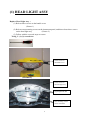
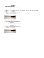
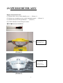
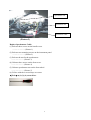
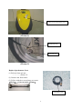
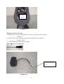
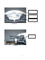
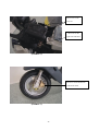
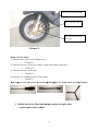
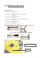
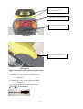
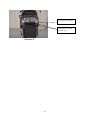
EVT-4000e
Maintenance Manual
EVT TECHNOLOGY CO., LTD.
1
(1) HEAD LIGHT ASSY
Replace Head Light Assy :
(1) Release three screws on the handle cover
(Picture 1)
(2) Release two mounting screws on the instrument panel, and then release three screws
on the head light assy
(Picture 2)
(3) Follow with the reversed steps to restore
Tools! " (1) (2) screwdriver
Three screws on
the handle cover
(Picture 1)
Three screws on
the head light assy
Signal light bulb set
Two mounting screws
on the instrument
2
(Picture 2)
Replace Head Light Bulb"
(1) Release three screws on the handle cover
(Picture 1)
(2) Release two mounting screws on the instrument panel so can easily replace the
bulb
(Picture 2)
(3) Follow with the reversed steps to restore
Tools! " (1) (2) screwdriver
Replace Signal Light Bulb"
(1) Release three screws on the handle cover
(Picture 1)
(2) Release signal light bulb set for replacement
(Picture 2)
(3) Follow with the reversed steps to restore
Tools! " (1) screwdriver
3
(2) SPEEDOMETER ASSY
Replace Instrument Panel :
(1) Release three screws on the handle cover……(Picture 1)
(2) Release two mounting screws on the instrument panel……(Picture 2)
(3) Release the nut for the speedometer……(Picture 3)
(4) Follow with the reversed steps to restore
<Tools>:(1) (2) screwdriver
Three screws on
the handle cover
(Picture 1)
Two mounting
screws on the
instrument panel
(Picture 2)
4
Speedometer bolt
Speedometer nut
Speedometer cable
(Picture 3)
Replace Speedometer Cable:
(1) Release three screws on the handle cover
…………………(Picture 1)
(2) Release two mounting screws on the instrument panel
…………………(Picture 2)
(3) Release the nut for the speedometer
…………………(Picture 3)
(4) Release three screws on the front cover
…………………(Picture 4)
(5) Release speedometer nut on the front wheel
…………………(Picture 5)
(6) Follow with the reversed steps to restore
<Tools>:(1) (2) (4) screwdriver
5
Three screws on the front cover
(Picture 4)
Speedometer nut
Front axle nut
(Picture 5)
Replace Speedometer Gear:
(1) Release front axle nut
……………(Picture 5)
(2) Remove the front wheel
(3) Follow with the reversed steps to restore
<Tools>:(1) box wrench(17mm)
Speedometer gear
6
(3) KEY SWITCH AND HORN
Replace Key Switch :
(1) Release three screws on the front cover
………………(Picture 1)
(2) Release six screws on the front fender
………………(Picture 1)
(3) Release three screws on the glove box
………………(Picture 2)
(4) Release 4 pin connector and two screws on the key switch
………………(Picture 3)
(5) Follow with the reversed steps to restore
<Tools>:(1) (2) screwdriver;(3) T-bend socket wrench(8mm)& screwdriver;
(4) T-bend socket wrench(10mm)
Three screws on the
front cover
Six screws on the
front fender
(Picture 1)
7
Three screws on
the glove box
(Picture 2)
Two screws for the key
switch on left and right side
4 pin connector
(Picture 3)
8
Replace Horn:
(1) Release three screws on the front cover
………………(Picture 1)
(2) Release two connectors on the horn
………………(Picture 2)
(3) Release the mounting screws on the horn
………………(Picture 4)
(4) Follow with the reversed steps to restore
<Tools>:(1) screwdriver;(3) open-end wrench(10mm)
Two mounting screws
on the horn
Two connectors on
the horn
(Picture 4)
9
(4) MAIN CONTROL CORD
Replace Main Control Cord :
(1) Release three screws on the handle cover, two mounting screws on the instrument panel,
three screws on the head light, three screws on the front cover and two screws on the right
trim
………………(Picture 1 & 2)
(2) Release all of the connectors stored inside the handle cover
………………(Picture 3)
(3) Release all of the connectors stored inside the front cover
………………(Picture 4)
(4) Release all of the connectors stored inside the right cover
………………(Picture 5)
(5) Follow with the reversed steps to restore
<Tools>:(1) screwdriver
Three screws on
the handle cover
Three screws on the
front cover
(Picture 1)
10
Three screws on
the head light
Two mounting
screws on the
instrument panel
(Picture 2)
Connectors inside the handle cover
6 pin connector for left
handle switch
Connectors for
power cut off and
brake functions
6 pin connector for the
head light assy
4 pin connector for right
12 pin connector for
2 pin connector for
speedometer assy
Instrument panel
handle switch
3 pin connector for
light
E/P switch
2 pin connector for
flasher relay
(Picture 3)
11
Connectors inside the front cover
4 pin connector for key switch
4 pin connector for DC
to DC converter
Two connectors for the horn
(Picture 4)
Connectors inside the right cover
6 pin connector for the
tail light assy
9 pin black connector
9 pin white connector
2 pin white connector
(Picture 5)
12
Replace Flasher Relay:
(1) Release three screws on the handle cover, remove the rubber sleeve so can see the 2 pin
connector for the flasher relay
………………(Picture 1 & 6)
(2) Follow with the reversed steps to restore
<Tools>:(1) screwdriver
Rubber sleeve and 2 pin
connector for flasher
relay
(Picture 6)
13
DC to DC
converter
(Picture 7)
Replace DC to DC converter:
(1) Release three screws on the front cover so can see the DC to DC converter
………………(Picture 7)
(2) Release two screws and 4 pin connector for the DC to DC converter
………………(Picture 7 & 8)
(3) Follow with the reversed steps to restore
<Tools>:(1) (2) screwdriver
4 pin connector for DC to DC
converter
(Picture 8)
14
(5) HANDLE SWITCH LEFT AND RIGHT
Replace Left Handle Switch:
Remove left rear view mirror and release three screws on the handle cover
………………(Picture 1)
(1) Release two mounting screws on the instrument panel
………………(Picture 1)
(2) Release two screws on the left handle switch
………………(Picture 1)
(4) Follow with the reversed steps to restore
<Tools>:(1) open-end wrench(14mm)& screwdriver;(2) (3) screwdriver
Two screws on the
left handle switch
Two mounting
screws on the
instrument panel
(Picture 1)
15
Replace Right Handle Switch:
(1) Remove the right rear mirror and three screws on the handle cover
………………(Picture 2)
(2) Release two mounting screws on the instrument panel
………………(Picture 1)
(3) Release two screws on the right handle switch and one screw for the throttle cable
………………(Picture 2)
(4) Follow with the reversed steps to restore
<Tools>:(1) open-end wrench(14mm)& screwdriver;(2) (3) screwdriver
Two mounting screws on
the right handle switch
The screw for the
throttle cable
(Picture 2)
16
(6) BRAKE MASTER CYLINDER R & L
Replace Master Cylinder Right and Left:
(1) Release three screws on the handle cover, two mounting screws on the instrument panel
and three screws on the head light assy
………………(Picture 1 & 2)
(2) Check the fluid in reservoir for refuel or replace the brake fluid
………………(Picture 2)
(3) Replace reservoir
(a) Gasket fail or wear out (b) leaking
(4) Release the screw on the brake hose
………………(Picture 2)
(5) Release two screws on the reservoir
………………(Picture 3)
<Tools>:(1) screwdriver;(4) box wrench(12mm);(5) hex-key wrench(5mm)
Three screws on the
handle cover
(Picture 1)
17
Three screws on the head
light assy
The screw on the brake
hose
Two mounting screws on
the instrument panel
(Picture 2)
Two screws on the
reservoir
(Picture 3)
18
(7) FRONT FORK AND REAR
SHOCK ABSORBER
Replace Front Fork:
(1) Release three screws on the front cover
………………(Picture 1)
(2) Release six screws on the front fender
………………(Picture 2)
(3) Release three screws on the glove box
………………(Picture 3)
(4) Release clamping screw for the handle
………………(Picture 4)
(5) Release front axle nut to remove the wheel
………………(Picture 5)
(6) Release two screws on the caliper
………………(Picture 6)
(7) Release two screws on the front fork and check the steel balls to see if they are
missing……………… (Picture 4)
(8) Properly adjust the front fork clearance and follow the reversed steps to restore
<Tools>:(1) (2) screwdriver;(3) T-bend socket wrench(8mm)& screwdriver;
(4) box wrench(14mm)
;(5) box wrench(17mm)
;(6) Y-bend socket wrench(12mm);
(7) special wrench
19
Three screws on
(Picture 1)
Six screws on
the front fender
(Picture 2)
20
Three screws
(Picture 3)
The clamping screw
on the handle
Two screws on
(Picture 4)
21
Front axle nut
(Picture 5)
Two screws
(Picture 6)
22
Replace Rear Shock Absorber:
(1) Release two screws on the trim on each left and right side
………………(Picture 7)
(2) Release two screws on the left shock absorber
………………(Picture 9)
(3) Same as above mentions to replace the right shock absorber
(4) Follow with the reversed steps to restore
<Tools>:(1) screwdriver;(2) T-bend socket wrench(12mm,14mm)
Two screws on the
trim on each left and
right side
(Picture 7)
23
Left and Right shock
absorber
(Picture 8)
Two screws on the
shock absorber
(Picture 9)
24
(8 ) BRAKE HOSE FRONT & REAR
Replace Front Brake Hose:
(1) Release three screws on the handle cover
………………(Picture 1)
(2) Release two screws on the right reservoir
………………(Picture 2)
(3) Release the screw on the brake hose of the front wheel, avoid fluid leaking to the
pad ………………(Picture 3)
(4) Release the screw on the right side brake hose
………………(Picture 2)
(5) Release three screws on the front cover
………………(Picture 4)
(6) Cut off the band, and then pull out the hose slowly
(7) Follow with the reversed steps to restore
<Tools>:(1) (2) screwdriver;(3) (4) box wrench(12mm);(5) screwdriver;
(6) diagonal cutting pliers
Three screws on the
handle cover
(Picture 1)
25
Two screws on the
reservoir
The screw on the
right side brake hose
(Picture 2)
The screw on the brake hose
of the front wheel
(Picture 3)
26
Three screws on the front cove r
Six screws on the front
fender
(Picture 4)
Two screws on the reservoir
The screw on the right side
brake hose
(Picture 5)
27
Replace Rear Brake Hose:
(1) Release three screws on the handle cover
………………(Picture 1)
(2) Release two screws on the left reservoir
………………(Picture 5)
(3) Release the screw on the brake hose of the rear wheel, avoid fluid leaking to the
pad ………………(Picture 6)
(4) Release the screws on the left side brake hose
………………(Picture 5)
(5) Release three screws on the front cover
………………(Picture 4)
(6) Release six screws on the front fender
………………(Picture 4)
(7) Release two screws on the left trim
(8) Cut off the band, pull out the hose slowly
(9) Follow with the reversed steps to restore
<Tools>:(1) (2) screwdriver;(3) (4) box wrench(12mm);(5) (6) (7) screwdriver;
(8) diagonal cutting pliers
The screw on the brake
hose of the rear wheel
(Picture 6)
28
(9) CALIPER FRONT & REAR
Replace Front Caliper:
(1) Release three screws on the handle cover
………………(Picture 1)
(2) Release the screw on the front caliper, avoid fluid leaking to the pad
………………(Picture 2)
(3) Release the screw on the pad, and then remove the pad
………………(Picture 2)
(4) Release two mounting screws on the caliper
………………(Picture 2)
<Tools>:(1) screwdriver;(2) box wrench(12mm)
;(3)(4)Y-bend socket wrench(12mm)
;
Three screws on the
handle cover
(Picture 1)
29
The screw on the front caliper
The screw on the pad
Two mounting screws on
the caliper
(Picture 2)
Replace Rear Caliper:
(1) Release three screws on the handle cover
………………(Picture 1)
(2) Release the screw on the rear caliper, avoid fluid leaking to the pad
………………(Picture 3)
(3) Release the screw on the pad
………………(Picture 3)
(4) Release two mounting screws on the caliper
………………(Picture 3)
<Tools>:(1) screwdriver;(2) box wrench(12mm)
;(3)(4) Y-bend socket wrench(12mm)
* Refuel the brake fluid and pump out the air right after
replacement of the caliper.
30
The screw on the rear caliper
The screw on the pad
Two mounting screws on the
rear caliper
(Picture 3)
31
(10) CONTROLLER
Replace Controller:
(1) Release two screws on the right side trim
………………(Picture 1)
(2) Release the connectors of controller wire harness (black×1、red×1、black 9 pin×1、white 9
pin×1). Release the copper nut of throttle cable and pull it out, then you can see a small
hole on the throttle pillar, put a nail through the hole so can prevent the pillar to draw back
……………… (Picture 1 & 2)
(3) Release four screws on the controller, and cut off the band to remove the
controller ………………(Picture 1)
(4) Follow with the reversed steps to restore
<Tools>:(1) (3) screwdriver
Two screws on the right side trim
Four screws on the controller
The throttle pillar
(Picture 1)
32
Controller wire harness
(Picture 2)
Tie band to prevent the
pillar to draw back
The Throttle pillar
(Picture 3)
33
(11) MOTOR AND BRAKE DISK
Replace Motor:
(1) Release the black connector of the motor cord
………………(Picture 1)
(2) Cut off the band
………………(Picture 1)
(3) Release three screws on the motor cord cover
………………(Picture 1)
(4) Release two nuts for the motor shaft
………………(Picture 2)
(5) Release the rear caliper so can remove the motor
………………(Picture 3)
(6) Follow with the reversed steps to restore
<Tools>:(2) diagonal cutting pliers;(3) screwdriver;(4) open-end wrench(24mm);
(5) Y-bend socket wrench(12mm)
Motor cord
Three tie bands on the
main cord
Three screws on the
motor cover
(Picture 1)
34
Two nuts for the motor shaft
(Picture 2)
Two screws for the brake assy
(Picture 3)
35
Replace Rear Brake Disk:
(1) Release the black connector of the motor cord
………………(Picture 1)
(2) Cut off the band (Picture 1)
(3) Release three screws on the motor cord cover (Picture 1)
(4) Release two nuts for the motor shaft (Picture 2)
(5) Release the rear caliper so can remove the motor (Picture 2)
(6) Release three screws on the brake disk so can remove the disk
(7) Follow with the reversed steps to restore
<Tools>:(2) diagonal cutting pliers ;(3) screwdriver;(4) open-end wrench(24mm);
(5) Y-bend socket wrench(12mm);(6) hex-key wrench(6mm)
Three screws on the disk
(Picture 4)
36
Replace Front Brake Disk:
(1) Release the screw for the front axle nut to remove the front wheel
……………(Picture 5)
(2) Release three screws on the disk
(3) Follow with the reversed steps to restore
<Tools>:(1) box wrench(17mm);(2) hex-key wrench(6mm)
The screws for the
front axle nut
(Picture 5)
Three screws on the
brake disk
(Picture 6)
37
(12) REAR LIGHT ASSY
Replace Rear Light:
Release three screws on the tail comp
………………(Picture 1)
(1) Release four screws on the trim on each left and right side
…………………(Picture 2)
(3) Release the screw on the center cover
…………………(Picture 3)
(4) Release three screws on the side cover on each left and right side
…………………(Picture 2)
(5) Release two screws on the tail fender
…………………(Picture 2)
(6) Follow with the reversed steps to restore
<Tools>:(1) hex-key wrench(6mm)& Y-bend socket wrench(10mm);
(2) (3) (4) screwdriver;(5) T-bend socket wrench(10mm)
Three screws on the tail comp
Tail comp
(Picture 1)
38
Three screws on the side cover on
each left and right side
Two screws on the lamp cover
Two screws on the tail fender
(Picture 2)
The screw on the center cover
(Picture 3)
Replace the bulb for Rear Lamp & Signal Light:
(1) Release two screws on the rear lamp cover
………(Picture 2)
(2) Remove the cover so can replace the bulb
………(Picture 4)
(3) Follow with the reversed steps to restore
<Tools>:(1) screwdriver
39
The bulb for brake light
The bulb for the signal
left and right
(Picture 4)
40
EVT-4000e Trouble Shooting and Repair
Conditions
Inspect
Repair
Display Panel indicator light is working, but
1.
The power will cut off while braking. 1.
Release the brake and then gently twisting
there is no move while twisting throttle.
2.
Brake switch breakdown
throttle
3.
Check Controller cable is fixed
4.
Check Motor cable is fixed
5.
Motor breakdown
6.
Controller breakdown
2~6.See your agent
Display Panel indicator light is not working or 1.
Has the fuse blown
1.
Remove the fuse and replace or see your agent
no starting beep sound while you turn the
2.
Serious insufficient energy left
2.
Recharge battery
switch to the “ON” position.
3.
Key switch breakdown
3~7.See your agent
4.
Check main switch cable is fixed
5.
Controller breakdown
6.
Display panel breakdown
7.
The starting beeper breakdown.
1.
Serious insufficient energy left
1.
Recharge battery immediately
2.
The battery is aged or useless
2.
Replace the battery
The first red light blinking (1)
The second yellow light blinking (2)
1.Insufficient energy left
1.Recharge battery
(The power cut off while driving, please switch the
power to “OFF” position, and wait for several
minutes then restart You may still drive a short
distance.)
The third green light blinking while driving
1.
Over current
(3)
2.
Controller breakdown
The fourth green light blinking (4)
1.
for few seconds to restart.
2.
See your agent
1.
Throttle stuck
1.
See your agent
2.
Twisting throttle to pull away before
2.
Switch the power to “OFF” position, and wait
the panel indicator stop blinking or
the starting beep sound stop
The OH indicator blinking
Charging indicator is not lit
Switch the power to “OFF” position, and wait
3.
Controller breakdown
1.
Controller over heat
2.
Controller breakdown
1.
Are the outlet and inlet plugged
secure?
2.
Wrong input voltage
41
for few seconds to restart
3.
.See your agent
1.
Switch the power to “OFF” position, and wait
for several minutes than restart.
2.
See your agent
1.
Pull out and insert again or change outlet
42