1
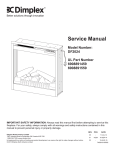
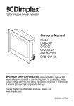
Service Manual
Model
BLF50
UL Part Number
6906780100
IMPORTANT SAFETY INFORMATION: Always read this manual first before attempting to service this
fireplace. For your safety, always comply with all warnings and safety instructions contained in this
manual to prevent personal injury or property damage.
Dimplex North America Limited
1367 Industrial Road Cambridge ON Canada N1R 7G8
1-888-346-7539 www.dimplex.com
In keeping with our policy of continuous product development, we reserve the right to make changes without notice.
© 2011 Dimplex North America Limited
REV
PCN
DATE
00
-
21-JUL-11
01
4-JAN-12
7400360000R01
TABLE OF CONTENTS
OPERATION. . . . . . . . . . . . . . . . . . . . . . . . . . . . . . . . . . . . . . . . . . . . . . . . . . . . . . . . . 3
EXPLODED PARTS DIAGRAM . . . . . . . . . . . . . . . . . . . . . . . . . . . . . . . . . . . . . . . . . . 4
WIRING DIAGRAM. . . . . . . . . . . . . . . . . . . . . . . . . . . . . . . . . . . . . . . . . . . . . . . . . . . . 5
PREPARATION FOR SERVICE . . . . . . . . . . . . . . . . . . . . . . . . . . . . . . . . . . . . . . . . . . 6
INSTRUCTIONS FOR REMOVING FROM WALL . . . . . . . . . . . . . . . . . . . . . . . . . . . . 7
Surface Mount. . . . . . . . . . . . . . . . . . . . . . . . . . . . . . . . . . . . . . . . . . . . . . . . . . . . . . . . . . . . . . . . 7
Recessed Mount - Partial In-wall . . . . . . . . . . . . . . . . . . . . . . . . . . . . . . . . . . . . . . . . . . . . . . . . . 8
Flush Mount – Complete In-wall. . . . . . . . . . . . . . . . . . . . . . . . . . . . . . . . . . . . . . . . . . . . . . . . . . 8
LED LIGHT STRIPS REPLACEMENT . . . . . . . . . . . . . . . . . . . . . . . . . . . . . . . . . . . . . 9
LED DRIVER BOARD REPLACEMENT. . . . . . . . . . . . . . . . . . . . . . . . . . . . . . . . . . . . 9
FLICKER MOTOR/FLICKER ROD REPLACEMENT. . . . . . . . . . . . . . . . . . . . . . . . . 10
ELEMENT REPLACEMENT. . . . . . . . . . . . . . . . . . . . . . . . . . . . . . . . . . . . . . . . . . . . 10
HIGH TEMPERATURE CUTOUT REPLACEMENT. . . . . . . . . . . . . . . . . . . . . . . . . . 10
BLOWER/FAN REPLACEMENT. . . . . . . . . . . . . . . . . . . . . . . . . . . . . . . . . . . . . . . . . . 11
ON/OFF SWITCH REPLACEMENT. . . . . . . . . . . . . . . . . . . . . . . . . . . . . . . . . . . . . . . 11
REMOTE SWITCHBOARD REPLACEMENT. . . . . . . . . . . . . . . . . . . . . . . . . . . . . . . 12
REMOTE CONTROL RECEIVER REPLACEMENT. . . . . . . . . . . . . . . . . . . . . . . . . . 12
POWER CORD REPLACEMENT. . . . . . . . . . . . . . . . . . . . . . . . . . . . . . . . . . . . . . . . 12
ASSEMBLY PART PICTURES . . . . . . . . . . . . . . . . . . . . . . . . . . . . . . . . . . . . . . . . . . 14
TROUBLESHOOTING GUIDE . . . . . . . . . . . . . . . . . . . . . . . . . . . . . . . . . . . . . . . . . . 18
Always use a qualified technician or service agency to repair this fireplace.
! NOTE: Procedures and techniques that are considered important enough to emphasize.
CAUTION: Procedures and techniques which, if not carefully followed, will result in damage to the
equipment.
Warning: Procedures and techniques which, if not carefully followed, will expose the user to the
risk of fire, serious injury, or death.
2
www.dimplex.com
OPERATION
Remote Control
The BLF50 operates in a 3-Stage process. These
stages can be controlled either by the remote control
or by the manual controls which are located on the
right side of the unit and inside the air intake slot
(Figure 1).
Figure 1
C
B
A
The fireplace is supplied with a radio frequency remote
control. This remote control has a range of approximately
50 feet (15.25 m), it does not have to be pointed at the
fireplace and can pass through most obstacles (including
walls). It is supplied with one of hundreds of independent
frequencies to prevent interference with other units.
! NOTE: Before attempting any operation with the
remote, pull the plastic insulator strip out from between
the remote casing and battery cover (Figure 2).
Remote Control Initialization/Reprogramming
Manual Controls
A.On/Off Switch
The On/Off Switch supplies power to all fireplace functions.
When the switch is in the “ -- ” position, the unit is on.
When in the “ O ” position, the fireplace is off.
B.3-Position Selection Switch
The 3-Position Selection Switch changes the mode
the fireplace operates in and has three (3) positions: “
MANUAL ”; “ OFF ”; and “ REMOTE ”.
When in “ REMOTE ” mode, the fireplace's three levels of
operation are controlled by the ON and OFF buttons of the
remote control.
In “ OFF ” mode, power to all functions is cut off.
In “ MANUAL ” mode, the fireplace's three levels of
operation are controlled by the Manual Control Buttons.
C.Manual Control Buttons
The Manual Control Buttons operate the fireplace levels
sequentially (from off): flames only; to flames and low heat;
to flames and high heat.
The level is increased every time the “ -- ” button is
pressed, and the fireplace can be turned off at any point by
pressing the “ O ” button.
Resetting the Temperature Cutoff Switch
Should the heater overheat, an automatic cut out will turn
the fireplace off and it will not come back on without being
reset. It can be reset by switching the On/Off Switch to Off
and waiting five (5) minutes before switching the unit back
on.
CAUTION: If you need to continuously reset the heater,
disconnect power and call Dimplex customer service at
1-888-DIMPLEX (1-888-346-7539).
If the remote control or receiver board has been replaced,
follow these steps to initialize the remote control and
receiver:
1. Ensure that power is supplied through the main service
panel.
2. Turn On/Off Switch to On (Figure 1A).
3. Move the 3-Position Selection Switch to the “REMOTE”
position (Figure 1B).
4. Press and hold the Manual Control Button marked “ -- ”
(Figure 1C) for five (5) seconds. After five (5) seconds,
there is a 10 second window to press any button on the
remote control.
5. Within 10 seconds press any button on the remote
control. If the unit does not initialize, turn the On/Off
Switch off for 30 seconds and try starting at Step 1.
This will synchronize the remote control and receiver.
Remote Control Usage
The remote control operates the fireplace levels
sequentially (from off): flames only; to flames and low heat;
to flames and high heat.
The level is increased every time the ON button is pressed
on the remote control and the fireplace can be turned off at
any point by pressing the OFF button.
Battery Replacement
To replace the battery:
1. Slide battery cover open on the Remote Control
(Figure 2).
2. Install one (1) 12-Volt (A23) battery in the battery
holder.
3. Close the battery cover
Figure 2
On
Button
Off Button
Plastic
Strip
Battery must
be recycled or
disposed of
properly. Check with
your Local Authority or
Retailer for recycling
advice in your area.
Battery
Cover
3
EXPLODED PARTS DIAGRAM
3
8
1
12
19
9
10
13
11
2
16
7
6
14
4
Replacement Parts List
1. Element. . . . . . . . . . . . . . . . . . . . . . . . . . 2200510500RP
2. Partially Reflective Glass . . . . . . . . . . . . 5901920100RP
3. Blower/Fan . . . . . . . . . . . . . . . . . . . . . . . 5300260100RP
4. Front Glass. . . . . . . . . . . . . . . . . . . . . . . 5901930100RP
5. Power Cord. . . . . . . . . . . . . . . . . . . . . . . 8400320100RP
6. Flicker Motor. . . . . . . . . . . . . . . . . . . . . . 2000220100RP
7. Flicker Rod . . . . . . . . . . . . . . . . . . . . . . . 5901910100RP
8. Cutout. . . . . . . . . . . . . . . . . . . . . . . . . . . 2300200100RP
9. LED Light Strips . . . . . . . . . . . . . . . . . . . 3000830102RP
10. Remote Control Receiver . . . . . . . . . . . . 3000820100RP
11. Remote Switchboard. . . . . . . . . . . . . . . . 3000820300RP
12. LED Driver Board . . . . . . . . . . . . . . . . . . 3000810100RP
13. On/Off Switch . . . . . . . . . . . . . . . . . . . . . 2800210200RP
14. Terminal Block. . . . . . . . . . . . . . . . . . . . . 4000070100RP
15. Capacitor. . . . . . . . . . . . . . . . . . . . . . . . . 3200030100RP
16. Remote Control. . . . . . . . . . . . . . . . . . . . 3000370600RP
17. Glass Ember Bed . . . . . . . . . . . . . . . . . . 1400070100RP
18. Hardware Kit. . . . . . . . . . . . . . . . . . . . . . 9600350100RP
19. Plastic Media Tray. . . . . . . . . . . . . . . . . . 5901940100RP
4
www.dimplex.com
LED DISPLAY BOARD
BLOWER
CUT OUT
ELEMENT
LED DRIVER BOARD
FLICKER MOTOR
TERMINAL BLOCK
CAPACITOR
SWITCH BOARD
WIRE NUT
CORD
3-STAGE RECEIVER BOARD- LINEAR
WIRE NUT
SWITCH- ON/OFF
WIRING DIAGRAM
5
PREPARATION FOR SERVICE
Figure 3
Mounts (4)
!
NOTE: All components are replaceable from the front
of the fireplace while the unit is mounted on the wall, with
the exception of replacement of the power cord.
! NOTE: If the power cord needs replacing or if the unit
needs to be removed from the wall for any other reason
please begin service by following the “PREPARATION
FOR SERVICE” instructions, then move on to the section
“INSTRUCTIONS FOR REMOVING FROM WALL”.
Tools Required: Philips head screwdriver
W
arning: Disconnect power before attempting any
maintenance or cleaning to reduce the risk of electric
shock or damage to persons.
CAUTION: If unit was operating prior to servicing allow
at least 10 minutes for lights and heating elements to cool
off to avoid accidental burning of skin.
1. Disconnect power source.
• Unplug the fireplace from the outlet.
• If unit has been hardwired for power or outlet is not
accessible from the front, turn the breaker off at the
electrical panel.
2. Remove the front glass assembly by removing the 2
screws (1 on the left and 1 on the right side, located
just inside the top front vent opening). These screws
secure the front glass panel to the inside of the
fireplace. (Figure 4)
3. Lift the front glass assembly off of the 4 mounts located
between the outer and inner casing of the fireplace: 2
on the left and 2 on the right. (Figure 3) Carefully place
the glass assembly aside in a safe location.
4. Remove the decorative glass ember-bed pieces from
the media tray, which lies along the bottom of the
interior Partially Reflective Glass. A medium sized
container such as a bucket or a box will be needed to
keep the glass ember-bed pieces together.
! NOTE: Try to ensure the pieces do not get pushed or
wedged underneath the Partially Reflective Glass. They
may obstruct the ease of removing the Partially Reflective
Glass from the fireplace.
5. Remove the Partially Reflective Glass by removing the
2 screws on each bracket; (2-brackets in total), located
on the left and right side of the Partially Reflective
Glass.
6. With one hand gently supporting the Partially Reflective
Glass, carefully pry the Partially Reflective Glass
forward from the upper half so that it begins to tilt
forward from the top. Grasp the Partially Reflective
Glass from the sides and carefully lift it up and out from
the front of the fireplace. Set it aside in a safe place.
7. Remove the plastic media tray by removing the 6
screws: 3 on the left and 3 on the right of the tray.
(Figure 5)
8. The tray has a small lip that goes underneath and
slightly up behind the Partially Reflective Glass - from
Hooks (4)
Figure 4
Figure 5
Tab
Media Tray screws (6)
Front Panel
Front Panel tabs (2)
the front edge, pull the tray up and forward to take it out
of the fireplace.
CAUTION: Partially Reflective Glass is not tempered.
Do not bump or drop the Partially Reflective Glass to avoid
breakage and personal injury.
! NOTE: Once the repair is completed, replace the
media tray first before re-inserting the Partially Reflective
Glass.
• Re-place 1 screw on both the left and right side of
the media tray closest to the front to align the tray
and keep it in place.
• Put the Partially Reflective Glass with the rubber
protective strip at the top and secure with the side
mounting brackets
• Secure the remaining 4 screws in the media tray.
6
www.dimplex.com
Figure 6
48 12 " (123 cm)
46" (116 cm)
3" (7.6 cm)
7"
(17.8 cm)
50 5 16" (128 cm)
16"
(40.6 cm)
19 12
(49.5 cm)
18"
(45.7 cm)
3 13 16"
(9.7 cm)
9. Proceed to the instructions within this manual relating
to the repair being performed - see Table of Contents
for page number.
INSTRUCTIONS FOR REMOVING FROM
WALL
W
arning: Disconnect power before attempting any
maintenance or cleaning to reduce the risk of electric
shock or damage to persons.
CAUTION: If unit was operating prior to servicing allow
at least 10 minutes for lights and heating elements to cool
off to avoid accidental burning of skin.
! NOTE: Only required for replacement of the power
cord or removal from service.
CAUTION: Follow “Preparation for Service” instructions
before proceeding.
Mounting - The fireplace may be mounted in one of 3 methods:
• Surface Mount
• Recess Mount (partially in the wall)
• Flush Mount (completely in the wall)
Identify the type of mounting and follow the appropriate
instructions in the following pages. (See Figure 6 for the
top and side profile view with measurements of the back
panel).
CAUTION: Two people will be required for removal
and re-installation of the fireplace. The unit is approx. 50
5/16”w x 19 1/2”h x 7”d. Weight is approximately 75lbs.
CAUTION: To prevent injury or damage, turn off the
breaker in your electrical panel prior to attempting to remove this unit off the wall.
! NOTE: If fireplace is hard wired directly to the electrical panel, and there is not enough slack in the wires within
the wall to reach your work area, remove the electrical junction box cover located on the bottom right by removing the
1 screw on the front of the cover. Lift the cover off and set
aside. Disconnect the 3 wire connectors connected to the
power source, taking note of their original configuration.
Surface Mount
(Figure 7)
Tools Required: Philips head screwdriver
CAUTION: Follow “Preparation for Service” instructions
before proceeding.
1. Partially unscrew the rear mounting screws that are
holding the fireplace to the wall along the back panel
of the unit. Support the weight of the fireplace when
loosening the screws so unit does not fall off the wall
unexpectedly.
! NOTE: Be sure to take note of which keyhole mount
openings were used for positioning the fireplace so that
it can be re-placed in the same location when service is
complete. (Figure 7)
2. Take the fireplace off the wall by carefully lifting the
fireplace off the mounting screws so they line up to the
larger part of the keyhole openings and pull forward.
Carefully lay the unit down on a solid flat surface with
the front of the unit facing up.
Figure 7
Key-hole
Wall stud
Permanent
mounting hole
7
!
NOTE: If the surface you are using as a work area on
is a finished surface that is prone to scratches (i.e. hardwood flooring), it is recommended that a protective barrier
be used underneath, (i.e. cloth, cardboard, thick plastic).
3. Proceed to the instructions within this manual relating
to the repair being performed - see Table of Contents
for page number.
4. Once repair is complete, reassemble in the reverse
order as above.
Recessed Mount - Partial In-wall
(Figure 8)
Tools Required: Philips head screwdriver
CAUTION: Follow “Preparation for Service” instructions
before proceeding.
1. Remove the 4 mounting screws located approximately
3 inches deep in the space between the outer and inner casing on the left and right hand side. There are
2 screws per side, upper and lower going into a stud.
(Figure 9)
CAUTION: The fireplace should be supported while
removing the screws to prevent the unit from falling.
2. Remove the fireplace out of the opening by slightly lifting and pulling forward.
3. Carefully lay the unit down on a solid flat surface with
Figure 8
the front of the unit facing up.
! NOTE: If the surface you are using as a work area is
a finished surface that is prone to scratches (i.e. hardwood
flooring), it is recommended that a protective barrier be
used underneath, (i.e. cloth, cardboard, thick plastic).
4. Proceed to the instructions within this manual relating
to the repair being performed - see Table of Contents
for page number.
5. Once repair is complete, reassemble in the reverse
order as above.
Flush Mount – Complete In-wall
(Figure 10)
Tools Required: Philips head screwdriver
CAUTION: Follow “Preparation for Service” instructions
before proceeding.
1. Locate and remove the 4 mounting screws inside the
unit located on left and right side towards the front.
There are 2 screws per side, going from the side
panels out into the side of the wall stud that frames the
fireplace. (Figure 10)
CAUTION: The unit should be supported while removing the screws to prevent the unit from falling.
2. Remove the fireplace out of the opening by slightly lifting and pulling forward.
3. Carefully lay the unit down on a solid flat surface with
the front of the unit facing up.
! NOTE: If the surface you are using as a work area is
a finished surface that is prone to scratches (i.e. hardwood
flooring), it is recommended that a protective barrier be
used underneath, (i.e. cloth, cardboard, thick plastic).
4. Proceed to the instructions within this manual relating
Figure 10
Mounting Holes
Wall Surface
Figure 9
Mounting Holes
Mounting Hole
8
www.dimplex.com
to the repair being performed - see Table of Contents
for page number.
5. Once repair is complete, reassemble in the reverse
order as above.
LED LIGHT STRIPS REPLACEMENT
W
arning: Disconnect power before attempting any
maintenance or cleaning to reduce the risk of electric
shock or damage to persons.
CAUTION: If unit was operating prior to servicing allow
at least 10 minutes for lights and heating elements to cool
off to avoid accidental burning of skin.
Tools required: Phillips head screwdriver
Wire snips
CAUTION: Follow “Preparation for Service” instructions
before proceeding.
1. Partially release the lower face panel, by removing
the screw on the left side and on the right side of the
panel, inside the unit. Pull the front panel forward from
the topside by approximately 2” inches. There are 3
additional screws located underneath the front face but
do not need to be removed. There should be enough
“give” to allow the panel to pull slightly forward.
! NOTE: If the 3 bottom screws to the front panel are
accessible in your application, you can remove them to
obtain the most clearance for the repair. If they are not accessible, you can still proceed with them attached.
2. Remove the electrical junction box cover located on the
bottom right hand side by removing the screw on the
front of the cover. Lift the cover out and set aside.
3. Remove the flicker rod by slightly bending the rod and
pulling the rubber bushing off the motor arm located on
the bottom right. Remove the middle plastic bushing
by lifting it up off the center bracket. Slide the remainder of the flicker rod off the end bracket on the left.
CAUTION: When removing and replacing the flicker
motor try to keep any slight bending of the flicker rod
minimal so as to not damage it. If flicker rod is damaged, it
should be replaced to ensure proper operation.
4. On the top right side, just below the Remote Switchboard, remove the 2 screws that secure the upper
control panel cover. Remove the cover and set aside
to allow access to the LED Driver Board wires.
5. On the LED Driver Board (smaller board on the right),
remove the two (2) orange wire connectors and separate the wires - noting original configuration.
6. In the lower area of the fireplace, remove the 2 screws
on each LED light strip, which secure the strips to the
light strip covers.
7. Cut and remove plastic cable ties that hold the wires in
place from the LED light cover at the bottom and up to
the LED Driver Board at the top.
8. Gently pull the LED light strip wires up and around from
the side of the light covers to free the strips. The covers may require a small amount of pressure upward, to
allow a little “give” when feeding the wires around the
covers.
9. Lift and remove LED strips out of the light covers and
slide the wires out of the protective insulation.
10. Feed the wires from the new LED strip back through
the same protective insulation up to the LED Driver
Board.
11. Attach the new LED strips to the LED cover with the
screws from step 9.
12. Route wires around the light covers and re-attach the
covers with the screws from the outer bottom panel of
the fireplace.
13. Reconnect the wires at the LED Driver Board at the top
using the 2 orange wire connectors from STEP 6.
14. Route wires back into control panel area.
15. Reassemble in the reverse order as above.
LED DRIVER BOARD REPLACEMENT
W
arning: Disconnect power before attempting any
maintenance or cleaning to reduce the risk of electric
shock or damage to persons.
CAUTION: If unit was operating prior to servicing allow
at least 10 minutes for lights and heating elements to cool
off to avoid accidental burning of skin.
Tools required: Phillips head screwdriver
Needle nosed pliers
Wire snips
CAUTION: Follow “Preparation for Service” instructions
before proceeding.
1. On the top right side, just below the Remote Switchboard, remove the 2 screws that secure the upper
control panel cover. Remove the cover and set aside
to allow access to the LED Driver Board wires.
2. Remove the two (2) cable ties on the right to allow access to the wires of the LED Driver Board.
3. On the LED Driver Board (smaller board on the right),
remove the two (2) orange wire connectors and separate the wires - noting their original configuration.
4. Also on the LED Driver Board remove the 2 wire connectors that join the 2 white wires together and the two
black wires together.
5. To remove the Driver Board off the plastic mounts,
pinch the plastic mounting tabs with needle nose pliers.
Pull the old board off.
6. Connect the firebox wires onto the new LED Driver
Board. Spread the flange on the top of the plastic
mounting tabs apart and re-use them to re-secure
the new Driver Board into the fireplace. Line up the
holes on the Driver Board and gently press the new
board onto the mounts. Make sure the Driver Board is
secure.
7. Reassemble in the reverse order as above.
9
FLICKER MOTOR/FLICKER ROD
REPLACEMENT
W
arning: Disconnect power before attempting any
maintenance or cleaning to reduce the risk of electric
shock or damage to persons.
CAUTION: If unit was operating prior to servicing allow
at least 10 minutes for lights and heating elements to cool
off to avoid accidental burning of skin.
Tools required: Phillips head screwdriver.
CAUTION: Follow “Preparation for Service” instructions
before proceeding.
1. Partially release the lower face panel, by removing
the screw on the left side and on the right side of the
panel, inside the unit. Pull the front panel forward from
the topside by approximately 2” inches. There are 3
additional screws located underneath the front face but
do not need to be removed. There should be enough
“give” to allow the panel to pull slightly forward.
! NOTE: If the 3 bottom screws to the front panel are
accessible in your application, you can remove them to
obtain the most clearance for the repair. If they are not accessible, you can still proceed with them attached.
2. Remove the electrical junction box cover located on the
bottom right hand side by removing the screw on the
small mounting-flange on the front face of the junction
box cover. Lift the cover out and set aside. Once the
cover is removed, the flicker motor and terminal block
will now be visible.
3. Remove the flicker motor wires from the terminal block
by removing the 3 small Philips screws holding each
wire in place then gently pulling the wires out of the
terminal block - noting their original locations.
4. Remove the 2 screws holding the flicker motor to the
mounting bracket. Gently pull the motor away from the
flicker rod.
CAUTION: When removing and replacing the flicker
motor try to keep any slight bending of the flicker rod
minimal so as to not damage it. If flicker rod is damaged, it
should be replaced to ensure proper operation.
5. Properly orient the new flicker motor onto the motor
bracket and re-attach with the 2 mounting screws.
6. Reassemble in the reverse order as above.
ELEMENT REPLACEMENT
W
arning: Disconnect power before attempting any
maintenance or cleaning to reduce the risk of electric
shock or damage to persons.
CAUTION: If unit was operating prior to servicing allow
at least 10 minutes for lights and heating elements to cool
off to avoid accidental burning of skin.
Tools required: Phillips head screwdriver.
Needle nosed pliers.
Wire Snips
3/8” ratchet or wrench
CAUTION: Follow “Preparation for Service” instructions
before proceeding.
1. Remove the 4 screws that secure the angled switch
housing cover located just below the Remote Switchboard on the top right. Remove cover and set aside.
2. Remove the front panel that spans across the top front
facia. To do so, locate the 4 screws: 2 on the left and
2 right on the angled part behind the facia. Wires from
the switch housing are connected to this piece so carefully move it farther down in the body of the unit, to give
some room to access the heating assembly cover.
3. Remove the heating assembly cover in the top center
by removing the 10 screws on the side brackets: 5 on
the left and 5 on the right. Wires from the switch housing are connected to this piece, so carefully move it
farther down in the body of the unit, to give some room
to access the heating assembly housing.
4. Release the top panel of the heating assembly housing by removing 4 screws on the side brackets. Pull
the top panel of the heating assembly housing out from
between the brackets.
5. From the top panel of the heating assembly housing,
remove the 4 screws that hold the element cover to the
housing panel.
6. Disconnect wires from the ends of the elements noting
their original locations.
! NOTE: Using a flat head screwdriver gently pry between the end of the connectors and the element to release
the wires.
! NOTE: Some of the wires may have a “piggy-back”
connector that allows a second wire to connect to the same
prong as the first wire. Try and keep the “piggy-back” connection together when pulling the wires off the element.
7. Using a 3/8” ratchet or wrench remove the hex head
screw from both sides of the element. Remove elements from the element housing and replace with the
new elements.
8. Reassemble in the reverse order as above.
CAUTION: When re-installing covers and panels, be
sure the wires are guided and tucked into the proper openings along the right side so they are not pinched and allows
enough space to reinstall panel.
HIGH TEMPERATURE CUTOUT
REPLACEMENT
W
arning: Disconnect power before attempting any
maintenance or cleaning to reduce the risk of electric
shock or damage to persons.
CAUTION: If unit was operating prior to servicing allow
at least 10 minutes for lights and heating elements to cool
off to avoid accidental burning of skin.
Tools required: Phillips head screwdriver
Needle nosed pliers
Wire Snips
10
www.dimplex.com
CAUTION: Follow “Preparation for Service” instructions
before proceeding.
1. Remove the 4 screws that secure the angled switch
housing cover located just below the Remote Switchboard on the top right. Remove cover and set aside.
2. Remove the front panel that spans across the top front
facia. To do so, locate the 4 screws: 2 on the left and
2 right on the angled part behind the facia. Wires from
the switch housing are connected to this piece so carefully move it farther down in the body of the unit, to give
some room to access the heating assembly cover.
3. Remove the heating assembly cover in the top center
by removing the 10 screws on the side brackets: 5 on
the left and 5 on the right. Wires from the switch housing are connected to this piece, so carefully move it
farther down in the body of the unit, to give some room
to access the heating assembly housing.
4. Release the top panel of the heating assembly housing by removing 4 screws on the side brackets. Pull
the top panel of the heating assembly housing out from
between the brackets.
5. Locate the high temperature cutout and remove the
mounting screw.
6. Disconnect the wiring connections noting their original
locations.
3. Remove the heating assembly cover in the top center
by removing the 10 screws on the side brackets: 5 on
the left and 5 on the right. Wires from the switch housing are connected to this piece, so carefully move it
farther down in the body of the unit, to give some room
to access the heating assembly housing.
4. Release the top panel of the heating assembly housing by removing 4 screws on the side brackets. Pull
the top panel of the heating assembly housing out from
between the brackets.
5. From the top panel of the heating assembly housing,
locate and remove the 6 screws that hold the blower/
fan assembly to the housing panel. Separate the
blower assembly from the housing panel.
CAUTION: When removing the blower assembly
mounting screws support the assembly to prevent any
damage to the unit.
6. Disconnect the wiring connections noting their original
locations.
! NOTE: Using a flat head screwdriver gently pry between the end of the connectors and the cutout to release
the wires.
7. Cut and remove plastic cable tie that hold the wires in
place on the top of the panel.
8. Properly orient the new high temperature cutout and
connect all of the wiring connections.
9. Reassemble in the reverse order as above.
ON/OFF SWITCH REPLACEMENT
BLOWER/FAN REPLACEMENT
W
arning: Disconnect power before attempting any
maintenance or cleaning to reduce the risk of electric
shock or damage to persons.
CAUTION: If unit was operating prior to servicing allow
at least 10 minutes for lights and heating elements to cool
off to avoid accidental burning of skin.
Tools required: Phillips head screwdriver.
Needle nosed pliers.
CAUTION: Follow “Preparation for Service” instructions
before proceeding.
1. Remove the 4 screws that secure the angled switch
housing cover located just below the Remote Switchboard on the top right. Remove cover and set aside.
2. Remove the front panel that spans across the top front
facia. To do so, locate the 4 screws: 2 on the left and
2 right on the angled part behind the facia. Wires from
the switch housing are connected to this piece so carefully move it farther down in the body of the unit, to give
some room to access the heating assembly cover.
! NOTE: Using a flat head screwdriver gently pry
between the end of the connectors and the blower/fan to
release the wires.
7. Properly orient the new blower/fan assembly and connect all of the wiring connections.
8. Reassemble in the reverse order as above.
W
arning: Disconnect power before attempting any
maintenance or cleaning to reduce the risk of electric
shock or damage to persons.
CAUTION: If unit was operating prior to servicing allow
at least 10 minutes for lights and heating elements to cool
off to avoid accidental burning of skin.
Tools required: Phillips head screwdriver.
Needle nosed pliers.
CAUTION: Follow “Preparation for Service” instructions
before proceeding.
1. Remove the 4 screws that secure the angled switch
housing cover located just below the Remote Switchboard on the top right. Remove cover and set aside.
2. Remove the front panel that spans across the top front
facia. To do so, locate the 4 screws: 2 on the left and
2 right on the angled part behind the facia. Wires from
the switch housing are connected to this piece so carefully rotate it up 180 degrees and move it farther down
in the body of the unit, to give some room for access.
This will make the switch visible from behind.
3. Disconnect the wiring connections noting their original
locations.
! NOTE: Using a flat head screwdriver gently pry between the end of the connectors and the switch to release
the wires.
4. Using needle nose pliers, pinch the tabs on either side
of the switch to release and push the switch forward
out of the front of the panel.
11
! NOTE: Note the orientation of the switch prior to
removing.
5. From the front of the panel, insert new switch by pushing switch back through the hole past the side tabs on
the switch, securing it in the opening.
6. Reconnect wires onto the prongs at the back of the
switch in their original configuration.
7. Reassemble in the reverse order as above.
REMOTE SWITCHBOARD
REPLACEMENT
W
arning: Disconnect power before attempting any
maintenance or cleaning to reduce the risk of electric
shock or damage to persons.
CAUTION: If unit was operating prior to servicing allow
at least 10 minutes for lights and heating elements to cool
off to avoid accidental burning of skin.
Tools required: Phillips head screwdriver.
Needle nosed pliers
Wire snips
CAUTION: Follow “Preparation for Service” instructions
before proceeding.
1. Remove the 4 screws that secure the angled switch
housing cover located just below the Remote Switchboard on the top right. Remove cover and set aside.
2. Remove the front panel that spans across the top front
facia. To do so, locate the 4 screws: 2 on the left and
2 right on the angled part behind the facia. Wires from
the switch housing are connected to this piece so carefully rotate it up 180 degrees and move it farther down
in the body of the unit, to give some room for access.
This will make the switch visible from behind.
3. Disconnect the wiring connections noting their original
locations.
! NOTE: Using a flat head screwdriver gently pry
between the end of the connectors and the switchboard to
release the wires.
4. To remove the switchboard off the plastic mounts, cut
or pinch the plastic mounting tabs with snips or needle
nose pliers. Pull the old board off.
5. Push the old mounts out towards the front/top of the facia panel. Insert and push the new mounts all the way
through into the same opening. Line up the holes on
the switchboard and gently press the new board onto
the mounts. Make sure the board is secure.
6. Reconnect the wires onto the back of the switchboard
in its original configuration. .
7. Reassemble in the reverse order as above.
REMOTE CONTROL RECEIVER
REPLACEMENT
W
arning: Disconnect power before attempting any
maintenance or cleaning to reduce the risk of electric
shock or damage to persons.
CAUTION: If unit was operating prior to servicing allow
at least 10 minutes for lights and heating elements to cool
off to avoid accidental burning of skin.
Tools required: Phillips head screwdriver.
Needle nosed pliers.
Wire snips
CAUTION: Follow “Preparation for Service” instructions
before proceeding.
1. On the top right side of the back panel, just below the
manual control switches, remove the 2 screws that secure the upper control panel cover. Remove the cover
and set aside to allow access to the Remote Control
Receiver wires (the board is the larger circuit board on
the left).
2. Remove any plastic cable ties to allow for easier removal of the wires on the Remote Control Receiver.
3. Remove the wires off the Remote Control Receiver,
taking careful note of the original location of the wires.
! NOTE: Using a flat head screwdriver gently pry between the end of the connectors and the receiver to release
the wires.
! NOTE: Some of the wires may have a “piggy-back”
connector that allows a second wire to connect to the same
prong as the first wire. Try and keep the “piggy-back”
connection together when pulling the wires off the Remote
Control Receiver.
4. To remove the Remote Control Receiver off the plastic
mounts, pinch the plastic mounting tabs with needle
nose pliers. Pull the old board off.
5. Attach the firebox wires onto the new Remote Control
Receiver. Spread the flange on the top of the plastic
mounting tabs apart and re-use them to re-secure the
new Remote Control Receiver into the firebox. Line up
the holes on the Remote Control Receiver and gently press the new Remote Control Receiver onto the
mounts - making sure the board is secure.
6. Reassemble in the reverse order as above.
POWER CORD REPLACEMENT
W
arning: Disconnect power before attempting any
maintenance or cleaning to reduce the risk of electric
shock or damage to persons.
CAUTION: If unit was operating prior to servicing allow
at least 10 minutes for lights and heating elements to cool
off to avoid accidental burning of skin.
Tools required: Phillips head screwdriver.
Needle nosed pliers.
CAUTION: Follow “Preparation for Service” instructions
before proceeding.
CAUTION: Follow “Instructions from Removing from
Wall” before proceeding.
1. Partially release the lower face panel. There are 5
screws in total are holding the panel: 1 screw on the
left and 1 on the right, inside the unit. There are 3 ad-
12
www.dimplex.com
2.
3.
4.
5.
6.
7.
8.
ditional screws located underneath the front face but do
not need to be removed.
If the 3 bottom screws to the front panel are accessible
in your application, you can remove them to obtain the
most clearance for the repair. If they are not accessible, you can still proceed with them attached and
pulling the front panel forward from the top end by approximately 2” inches.
Remove the electrical junction box cover located on the
bottom right hand side. Lift the cover out and set aside.
Remove power cord junction box by removing the 3
screws located on the, bottom left corner of the firebox:
2 screws are on the outer bottom panel and 1 screw is
on the outer back panel.
Unscrew the 2 wire connectors that join the power cord
at the bottom to the wire leads coming down from the
top.
With a pair of needle nose pliers, open the strain relief
bushing that holds the power cord in place on the junction box and remove the cord.
Feed the new power cord through the junction box and
squeeze the new strain relief in place on the cord and
junction box. Re-connect wires. –(Wide blade on the
plug is the neutral side of the power cord).
Reassemble in the reverse order as above.
13
ASSEMBLY PART PICTURES
3-STAGE REMOTE CONTROL RECEIVER
LED DRIVER BOARD
MANUAL CONTROLS - Outside View
REMOTE SWITCHBOARD - Inside View
14
www.dimplex.com
LOWER ELECTRICAL HOUSING
With Housing-Cover and Flicker Rod in place
LOWER ELECTRICAL HOUSING
With Housing-Cover and Flicker Rod Removed
LED LIGHT STRIPS
15
LED LIGHT STRIP WIRE HARNESS
Heating assembly
ELEMENT CONNECTIONS
Left and Right Side
16
www.dimplex.com
HIGH TEMPERATURE CUTOUT
Below Element Housing
BLOWER MOTOR CONNECTIONS
Below Element Housing
17
TROUBLESHOOTING GUIDE
Problem
Cause
Solution
General
Circuit breaker trips or fuse
blows when unit is turned on
Short in unit wiring.
Trace wiring in unit.
Improper circuit current rating
Additional appliances may exceed the current rating
of the circuit breaker or fuse. Plug unit into another
outlet or install unit on a dedicated 15 amp circuit.
Unit turns on or off by itself
Remote Control has a similar frequency
to other remotes in the area.
Replace Remote Control. Initialize to Remote Control
Receiver.
Radio frequency disturbance from outside sources.
Replace Remote Control and Remote Control Receiver where necessary. Initialize Remote Control and
Receiver.
Defective Remote Control Receiver
Replace Remote Control Receiver. Initialize Remote
Control and Receiver.
Lights dim in room while the unit
is on
Unit is drawing close to circuit current
rating
Move the unit to another outlet or install unit on a dedicated 15 amp circuit
Power cord gets warm
Normal Operation
The power cord may get slightly warm to the touch
when the heater is on
Defective power cord
Replace power cord if cord gets too hot to touch.
Appearance
Fireplace does not turn on Manu- Improper operation
ally
No incoming power from the electrical
wall socket
Fireplace does not turn on using
the Remote Control
Refer to Operation Section
Check fuse/breaker panel
Loose wiring
Check wiring connections
Defective On/Off Switch
Replace On/Off Switch
Defective Remote Switchboard
Replace Remote Switchboard
Improper operation
Refer to Operation Section
Remote Control not initialized to fireplace Initialize the Remote Control
Remote Control not working
Install new battery into the Remote Control. Initialize
Remote Control where necessary
Replace Remote Control Receiver or Remote Control
where necessary. Initialize Remover Control and
Remote Control Receiver
Flame Frozen
Loose wiring.
Check wiring connections
Defective Flicker Motor
Replace Flicker Motor
Defective LED Driver Board
Replace LED Driver Board
Flame not bright or flame not
visible
Loose wiring
Check wiring connections
Defective LED Light Strip
Replace LED Light Strip
Flame Shutter
Defective Flicker motor
Replace Flicker motor
18
www.dimplex.com
Problem
Cause
Solution
Heater
Heater is not turning off
Heater is not turning on
Improper operation
Refer to Operation Section
Defective Remote Switchboard
Replace Remote Switchboard
Defective Remote Control Receiver
Replace Remote Control Receiver
Improper operation
Refer to Operation Section
Loose wiring
Trace wiring in unit.
Defective Remote Switchboard
Replace Remote Switchboard
Defective Heating Element
Replace Heating Element
Heater is turning off after a
couple of minutes of operation
Build up of dirt/dust in Blower/Fan
Ensure that exterior intake louvers and firebox cavity
are free of dirt/dust.
Defective Blower/Fan
Replace Blower/Fan
Heater emits an odor
Normal Operation
Normal operation is when the heater emits an odor
for a brief period after the heater is initially turned on.
The heater is burning off any dust accumulated during
manufacturing or operation.
Defective Heating Element
Replace Heating Element
Heater fan turns on but heater
lacks heat
Improper operation
Refer to Operation Section
Loose wiring
Trace wiring in unit
Defective Heating Element
Replace Heating Element
Heating element is glowing red
Normal Operation
Small glowing sections of the element are considered
normal.
Defective Blower/Fan
If larger glowing sections are causing the heater to trip
the thermal cutout, unplug unit, discontinue use and
replace Blower/Fan.
Loose wiring
Trace wiring in unit
Defective Remote Switchboard
Replace Remote Switchboard
Defective Blower/Fan
Replace Blower/Fan
Dirty Blower/Fan
Ensure that exterior intake louvers and firebox cavity
are free of dirt/dust.
Defective Blower/Fan
Replace Blower/Fan
Flicker rod hitting or rubbing against
internal components
Ensure rod is straight and mounted properly in the
bracket, spinning freely away from other components.
Replace if necessary.
Defective Flicker motor
Replace Flicker motor
Heater fan runs continuously
Noise
Excessive noise with the heater
on
Grinding or excessive noise with
the heater off
19