1
English
Fitting Instructions:
Tiger 800, Tiger 800XC, Tiger XR, Tiger XRx, Tiger XC, Tiger XCx
A9508166, A9508172 and A9508173
Thank you for choosing this Triumph genuine accessory kit. This accessory kit is the product of Triumph's use of proven
engineering, exhaustive testing, and continuous striving for superior reliability, safety and performance.
Completely read all of these instructions before commencing the installation of the accessory kit in order to become
thoroughly familiar with the kit’s features and the installation process.
These instructions should be considered a permanent part of your accessory kit, and should remain with it even if your
accessory-equipped motorcycle is subsequently sold.
16
5
4
Tiger 800
Tiger 800XC
18 13
20
8
11
6
1
7mm
6
24mm
11
1
10
7mm
2
5
17
3
24mm
15
(135mm)
6
Publication part number A9901548 Issue 1, ADC 11924
10
2
9
19
14
17
18
7
19
12
21
T1588
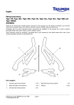
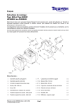
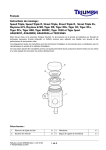
Parts Supplied:
1.
Pannier assembly, left hand
1 off
12. Screw, M6 x 20 mm
4 off
2.
Pannier assembly, right hand
1 off
13. Rocker arm, left hand
1 off
3.
Pannier upper mount, front
2 off
14. Rocker arm, right hand
1 off
4.
Pannier upper mount, rear
2 off
15. Cable cover
1 off
5.
Bolt, M8 x 80 mm
4 off
16. Third mount end plug
2 off
6.
Nut, M8
6 off
17.
Pivot bolt
2 off
7.
Pannier cable
1 off
18. Moulded cap
2 off
8.
Pannier third mount, left hand
1 off
19. Reflector, red
2 off
9.
Pannier third mount, right hand
1 off
20. Template
1 off
10. Bolt, M6 x 50 mm
4 off
21.
2 off
11.
4 off
22. Cleaning wipe (not shown)
Washer, M6
Publication part number A9900643 issue 6, DC 71806
© Triumph Designs Ltd. 2015
1 of 17
Protective film
1 off
Note:
Warning
•
This accessory kit is designed for use on Triumph
Tiger 800, Tiger 800XC, Tiger XR, Tiger XRx, Tiger XC,
Tiger XCx motorcycles only and should not be fitted to
any other Triumph model or to any other manufacturer’s
motorcycle. Fitting this accessory kit to any other Triumph
model, or to any other manufacturer’s motorcycle will
affect the performance, stability and handling of the
motorcycle. This may affect the rider’s ability to control the
motorcycle and could cause an accident.
•
•
Warning
Always have Triumph approved parts, accessories and
conversions fitted by a trained technician of an authorised
Triumph dealer. The fitment of parts, accessories and
conversions by a technician who is not of an authorised
Triumph dealer may affect the handling, stability or other
aspects of the motorcycle’s operation which may result in
loss of motorcycle control and an accident.
Warning
Throughout this operation, ensure that the motorcycle is
stabilised and adequately supported to prevent risk of
injury from the motorcycle falling.
Installation of the Pannier Third Mounts and
Pannier Cable
1.
Position the motorcycle on a paddock stand.
2.
Remove the rider’s seat, as described in the Owner’s
Handbook.
Note:
•
•
Warning
A torque wrench of known accurate calibration must be
used when fitting this accessory kit. Failure to tighten any
of the fasteners to the correct torque specification may
affect motorcycle performance, handling and stability. This
may result in loss of motorcycle control and an accident.
2 of 17
Ensure the Triumph Tiger 800, Tiger 800XC,
Tiger XR, Tiger XRx, Tiger XC, Tiger XCx Service
Manual is available for reference during the
fitting of this accessory kit.
For Tiger 800 and Tiger 800XC models up to
VIN 583614, a suitable hand-held power drill
with a 7 mm diameter drill bit and a 24 mm
diameter sheet metal punch are required to fit
this kit.
Triumph offers a broad range of approved
genuine accessories for your motorcycle. We
cannot therefore cover all possible equipment
variations in these instructions. For removal and
installation of Triumph Genuine Accessories
always refer to the instructions supplied with the
respective accessory kit.
•
•
For Tiger 800 and Tiger 800XC up to
VIN 583614, continue from step 3.
For
Tiger 800,
Tiger 800XC,
Tiger XR,
Tiger XRx,
Tiger XC,
Tiger XCx
from
VIN 583615 continue from step 30.
Lock nuts can be reused, providing resistance can
be felt when the locking portion passes over the
thread of the bolt or stud.
Always use the correct replacement lock nut as
recommended in the Triumph parts catalogue.
3.
Remove the diagnostic socket from its location on the
battery tray moulding. Move the diagnostic socket and
wiring harness away from the side of the battery tray
moulding.
7.
Carefully release the relay and wiring harness
grommet from their location at the rear of the battery
tray moulding.
1. Diagnostic socket
2. Location, battery tray moulding
1. Relay
2. Wiring harness grommet
3. Battery tray moulding
4.
8.
Remove the following components, as described in the
Service Manual:
• Battery
Remove the shouldered bolts and M6 x 20 mm
screws securing the seat hook mouldings and remove
the seat hook mouldings. Retain the seat hook
mouldings and fixings for reuse.
• Rear light
• Silencer.
5.
Remove the tool kit.
6.
Detach the twelve way alarm connector from the
battery tray moulding and position aside.
4
1. Seat hook moulding (right hand shown)
2. Shouldered bolt (right hand shown)
3. Screw, M6 x 20 mm (right hand shown)
4
1. Battery tray moulding
2. Twelve way alarm connector
3 of 17
9.
Remove the four screws and washers securing the
battery tray moulding to the motorcycle frame. Note,
one of the screws also retains the air intake duct.
Discard the screws. Retain the washers for reuse.
11.
Carefully lower the battery tray moulding to rest on the
rear tyre.
Caution
1. Battery tray moulding
2. Screw (right hand shown)
3. Washer (right hand shown)
When cutting the left hand and right hand templates from
the template sheet, always use the correct cutting tools
and personal protection equipment. Failure to use these
may result in personal injury.
10. Remove the air intake duct.
Note:
•
The template provided is actual size. When
cutting out the left hand and right hand images
ensure the cut is made accurately along the
outline.
12. Collect the template from the kit and carefully cut out
the left hand template, upper image '1'.
MM
MM
1. Air intake duct
MM
MM
1. Template '1', left hand
2. Template '2', right hand
4 of 17
13. Position the left hand template to the left hand outer
edge of the battery tray moulding, as shown. Secure
the template to the battery tray moulding using a
suitable adhesive masking tape (not supplied in the
kit).
Warning
When drilling the battery tray moulding take extreme care
not to allow the drill bit to come into contact with any part
of the motorcycle tyre. Any damage to the tyre could
result in unexpected deflation, leading to loss of
motorcycle control and an accident.
Warning
Before drilling or cutting any holes in the battery tray
moulding ensure all wiring harnesses and electrical
connectors are moved away from the area on the battery
tray moulding which is to be drilled or cut. Failure to move
the wiring harnesses or electrical connectors away from
the drilling or cutting area could result in damage to a
wiring harness or electrical connector and cause a
hazardous electrical problem. This could give rise to a
dangerous riding condition resulting in a fire, loss of
motorcycle control and an accident.
1. Battery tray moulding
2. Template '1', left hand
3. Adhesive tape
Caution
14. Carefully mark the centre of the 7 mm and 24 mm
holes indicated on the template.
17.
Care must be taken when drilling or cutting any holes in
the battery tray moulding. Damage to the battery tray
moulding may result from inadequate care while drilling
or cutting any holes rendering the battery tray moulding
unfit for further use and requiring replacement.
Using the markings as a guide carefully drill two 7 mm
holes on the left hand side of the battery tray moulding
and one 7 mm hole in the right hand side of the
battery tray moulding.
1. Template
2. Hole, 7 mm
3. Hole, 24 mm
15. Note the position of the 24 mm hole, remove and
discard the template.
16. Repeat steps 12 to 15 for the right hand template '2' on
the right hand side of the battery tray moulding.
18. Using the markings provided carefully drill suitable size
pilot holes for the 24 mm sheet metal punch.
5 of 17
19. Using the sheet metal punch carefully cut the 24 mm
hole in the left hand and right hand side of the battery
tray moulding.
24. Refit the seat hook mouldings and secure with the
original shouldered bolts and M6 x 20 mm screws.
Tighten the fixings to 5 Nm.
20. Remove any burrs from around all drilled/cut holes
which may have resulted from the drilling/cutting
process.
1. Seat hook moulding (right hand shown)
2. Shouldered bolt (right hand shown)
3. Screw, M6 x 20 mm (right hand shown)
1. Battery tray moulding
2. Hole, 7 mm (left hand shown)
3. Hole, 24 mm (left hand shown)
21.
25. Refit the relay block and cable grommet to the battery
tray moulding.
Carefully refit the battery tray moulding into position.
22. Refit the air intake duct. Ensure the air duct locates
correctly on the air box.
23. Using the four M6 x 20 mm screws from the kit,
together with the original washers secure the battery
tray moulding and air intake duct to the motorcycle
frame. Tighten the fixings to 6 Nm.
1. Relay
2. Grommet, wiring harness
26. Refit the diagnostic socket to the battery tray moulding.
4
1. Battery tray moulding
2. Screw, M6 x 20 mm (right hand shown)
3. Washer (right hand shown)
6 of 17
27. Fit the twelve way alarm connector to the new 7 mm
hole drilled on the left hand side of the battery tray
moulding, as shown.
31.
Collect the pannier cable from the kit.
32. Feed the end of the pannier cable with the curved
metal tubing, over the main wiring harness in the
battery tray moulding and through the large hole on
the left hand side of the battery tray moulding.
1. Battery tray moulding
2. Twelve way alarm connector
3. 7 mm drilled hole
28. Refit the following components, as described in the
Service Manual:
• Battery
• Rear light (do not refit the rear rack at this stage)
• Silencer.
29. Refit the tool kit.
30. Support the silencer and loosen its fixing. Raise the
silencer up and tighten its fixing to 15 Nm.
1.
2.
3.
4.
Battery tray moulding
Large hole
Pannier cable
Curved metal tubing
33. Feed the opposite end of the pannier cable through
the large hole on the right hand side of the battery tray
moulding.
34. Remove the front four blanking plugs from the
underside of the rear subframe, as shown. Retain the
blanking plugs if the motorcycle is to be returned to its
original condition.
2
1
cgon
4
1. Silencer mounting bracket fixing
2. Nut
1. Subframe
2. Blanking plugs
7 of 17
35. Fit the end plugs provided into the pannier third
mounts as shown.
37. Take a self-adhesive protective film from the kit. Peel
approximately 15 mm of the backing paper away from
one end of the protective film. Locate the protective
film against the right hand side of the rear subframe,
positioned as shown below.
1
1. Pannier third mount
2. End plug
3 mm
Note:
•
Read the warning notices printed on the cleaning
wipe packet in the fitting kit.
36. Using the cleaning wipe provided, clean the areas on
both the left and right hand sides of the rear subframe
shown in grey below.
1
1. Protective film position (right hand shown, left hand
similar)
38. When aligned correctly, carefully press the exposed
area of film onto the rear subframe.
39. Gradually peel away the backing paper from the
protective film, pressing the areas of exposed film to
the contours of the rear subframe until the protective
film is fully applied.
40. Use a soft, lint free cloth to press the protective film
firmly on to the rear subframe, removing air pockets
where necessary.
41.
1. Area to be cleaned (right hand shown, left hand similar)
8 of 17
Repeat steps 37 to 40 for the left hand side of the rear
subframe.
42. Whilst offering the left hand pannier third mount to the
motorcycle rear subframe, route the pannier cable
through the wire guide on the pannier third mount.
4
45. Fit the right hand pannier third mount to the
motorcycle rear subframe and secure using two
M6 x 50 mm bolts and M6 washers, in the orientation
shown. Tighten the bolts to 12 Nm.
1
1
3
3
2
1.
2.
3.
4.
2
Subframe
Left hand pannier third mount
Wire guide
Pannier cable
1. Right hand pannier third mount
2. Bolt, M6 x 50 mm
3. Washer, M6
43. Secure the left hand pannier third mount to the
motorcycle rear subframe using two M6 x 50 mm
bolts and M6 washers, in the orientation shown.
Tighten the bolts to 12 Nm.
46. Fit the moulded caps into the clevis section of the left
and right hand pannier third mounts, ensuring the
moulded caps locate correctly in the hole provided in
the clevis.
1
1
3
2
3
2
1. Left hand pannier third mount
2. Bolt, M6 x 50 mm
3. Washer, M6
1. Pannier third mount (left hand shown)
2. Clevis section
3. Moulded cap
44. Whilst offering the right hand pannier third mount to
the motorcycle rear subframe, route the pannier cable
through the wire guide on the pannier third mount.
9 of 17
Installation of the Upper Mounts
2.
Note:
•
•
1.
Remove the two nuts and bolts and remove the two
left hand pannier mounting plates.
• Retain the plates for reuse
For Tiger 800 and Tiger 800XC up to
VIN 583614, the rear rack has been removed
during installation of the pannier third mounts,
therefore continue from step 2.
For
Tiger 800,
Tiger 800XC,
Tiger XR,
Tiger XRx,
Tiger XC,
Tiger XCx
from
VIN 583615 continue from step 1.
• Retain the bolts for reuse if the motorcycle is to be
returned to its original condition
• Discard the nuts.
Remove the four fixings, retain for reuse and remove
the rear rack moulding.
2
1
1. Bolts/nuts (nuts not shown)
2. Pannier mounting plates
Note:
2
•
The front upper pannier mounts are identified by
an 'F' on the underside face, as shown.
1. Rear rack
2. Fixings
1. Front upper pannier mount
2. 'F' marking
10 of 17
3.
Assemble a front pannier upper mount with a pannier
mounting plate and M8 x 80 mm bolt, in the
orientation shown below.
Installation of the Rocker Arms
1.
Locate the outer cable into the bracket on the left hand
third mount, ensuring the washer is positioned as
shown below.
1
3
1. Front pannier upper mount
2. Pannier mounting plate
3. Bolt, M8 x 80 mm
4.
2
Fit the front pannier upper mount to the side panel on
the left hand side of the motorcycle, in the orientation
shown and retain with an M8 nut from the kit. Tighten
the nut to 20 Nm.
1. Pannier cable
2. Washer
3. Bracket, pannier third mount
Warning
When locating the rocker arm into the clevis section of the
third mount, ensure that the cable is correctly located into
the slot on the rocker arm. If the cable is not correctly
located it can be bent and permanently damaged during
rocker arm fitment which will cause incorrect cable
function. Incorrect cable function may cause the
motorcycle to become unstable leading to loss of control
and an accident.
1
2.
1
2
3
1. Front pannier upper mount
2. Bolt, M8 x 80 mm
3. Nut, M8
5.
Repeat steps 3 and 4 for the rear pannier upper
mount.
6.
Repeat steps 2 to 5 for the right hand side of the
motorcycle.
7.
Refit the rear rack moulding and tighten the fixings to
3 Nm.
11 of 17
Collect the rocker arms, shouldered bolts and two M8
nuts from the kit.
3.
Fit the end of the cable into the left hand rocker arm,
with the wheel of the rocker arm facing towards the
rear of the motorcycle and locate the rocker arm into
the clevis section of the third mount, as shown below.
Pannier Cable Adjustment
Warning
Cable adjustment must be carried out with the panniers
empty.
3
Adjustment of the pannier cable with the panniers loaded
will cause an incorrect adjustment to be set.
Rear of the
Motorcycle
Riding the motorcycle with panniers fitted and the cable
incorrectly adjusted may cause the motorcycle to become
unstable leading to loss of control and an accident.
4
2
1.
Check that the motorcycle is in an upright position on
a paddock stand or the centre stand (if fitted).
2.
Mount the panniers as described on page 14.
3.
From inside the battery tray moulding, slide the rubber
sleeve along the pannier cable to expose the cable
adjuster and lock nut.
1
1.
2.
3.
4.
4.
Pannier cable
Rocker arm
Wheel, rocker arm
Pannier third mount
Fit a shouldered bolt from the kit, with the head of the
bolt towards the front of the motorcycle, to retain the
rocker arm to the clevis of the left hand third mount. Fit
an M8 nut from the kit to secure the shouldered bolt.
Tighten the nut to 20 Nm.
2
4
1.
2.
3.
4.
Front of the
Motorcycle
4.
3
1
1. Clevis, pannier third mount
2. Rocker arm
3. Shouldered bolt
5.
Repeat steps 1 to 4 for the right hand side of the
motorcycle.
12 of 17
Pannier cable
Rubber sleeve
Cable adjuster
Lock nut
Loosen the pannier cable lock nut.
5.
Push the left hand pannier inwards towards the
motorcycle, as far as it will go, until the left hand rocker
arm contacts the top of the moulded cap in the clevis,
as shown.
9.
Check that the panniers are free to move smoothly
and are unobstructed. Rectify if necessary.
10. Fit the cable cover provided into the battery tray
moulding. The pegs on the cable cover locate into the
small holes in the battery tray moulding.
1
2
1
3
1. Rocker arm
2. Moulded cap
3. Clevis
6.
1. Battery tray moulding
2. Cable cover
While holding the left hand pannier in the position
described in step 5, turn the adjuster section of the
pannier cable so that the right hand rocker arm is
pushed outwards, away from the motorcycle, until it
contacts the bottom of the moulded cap in the clevis,
as shown below. This action will cause the right hand
pannier to be pushed outwards, away from the
motorcycle.
Warning
When the panniers are fitted, do not ride the motorcycle
with the pannier third mount and/or pannier cable
removed or incorrectly adjusted.
Riding the motorcycle with the pannier third mount and/
or pannier cable removed or incorrectly adjusted may
cause the motorcycle to become unstable leading to loss
of motorcycle control and an accident.
11.
Refit the rider’s seat, as described in the Owner’s
Handbook.
12. Remove the motorcycle from the paddock stand or
centre stand (if fitted).
Note:
2
•
1
1
3
1. Rocker arm
2. Moulded cap
3. Clevis
7.
When correctly adjusted, hold the adjuster section of
the cable and tighten the cable lock nut to 2.5 Nm.
8.
Slide the rubber sleeve to cover the cable adjuster.
13 of 17
Re-check the pannier cable adjustment and
operation at each service as recommended in the
'Maintenance and Adjustment' section of the
Owner’s Handbook.
Reflector Fitment - United States, Canada and
Singapore Only
1.
Mounting the Panniers
Warning
Peel the protective film from the back of each reflector.
The two panniers fitted to this motorcycle are designed to
be fitted as a pair. Never ride the motorcycle with only one
pannier installed. Riding the motorcycle with one pannier
installed may cause the motorcycle to become unstable
leading to loss of control and an accident.
Notice
Failure to fit a reflector to each pannier as shown
contravenes federal law and renders the motorcycle illegal
for road use in the United States, Canada and Singapore.
Always fit the reflectors as shown.
2.
Fit one reflector to each pannier, in the position shown,
ensuring the surface of the pannier is clean and free
from grease.
To install each pannier:
Note:
•
•
The same procedure can be followed to remove
and mount the left hand or the right hand
panniers.
The pannier is marked in three positions around
the lock barrel. To lock, open or release the
panniers, the key slot must align with the
corresponding symbols around the barrel as
shown.
4
3
1
2
1. Reflector
Lock Barrel Fitment
1
1.
Take a lock barrel and key (supplied with the
motorcycle), insert the key into the barrel and push the
barrel into position in the pannier until it clicks into
place.
Note:
•
The lock barrel will only fit one way.
2.
Check the operation of the lock barrel.
3.
Turn the key to the locked position and remove the
key.
4.
Fit a lock barrel to the remaining pannier in the same
manner.
1.
2.
3.
4.
14 of 17
Key slot (shown in the LOCK position)
Lock position symbol
Unlock position symbol
Release position symbol
1.
Insert the key into the lock. Turn the key to the
RELEASE position and lift the carrying handle to its
fully raised position.
To remove each pannier:
Note:
•
The same procedure can be followed to remove
and mount the left hand or the right hand
panniers.
2
2
1
1
1. Lock
2. Carrying handle
T0881
2.
Position the pannier to the motorcycle and engage the
fixed hooks of the pannier with the pannier mounting
points.
1. Lock
2. Carrying handle
3.
Ensure that the third mount rocker arm fits into the
locating cup moulded into the front of the pannier.
1.
1
2
1. Rocker arm (left hand shown)
2. Locating cup
4.
Lock the pannier to the pannier mountings by pressing
the carrying handle to the fully closed position whilst
turning the key to the LOCK position. Remove the key.
15 of 17
To unlock and remove the pannier from the pannier
mountings, turn the key to the RELEASE position and
lift the carrying handle to its fully raised position. Lift
the pannier free from the pannier mountings.
Pannier Operation
Note:
4
•
Due to the effective nature of the pannier lid
seal, reasonable force may be required to close
the lid to the second latch position.
2.
To close and lock the pannier, close the lid until the
second 'click' is heard. Turn the key to the LOCK
position and remove it.
3
2
Caution
When loading or unloading the panniers while the
panniers are fitted to the motorcycle, avoid applying load
to the pannier lids. Applying load to the pannier lids while
the panniers are fitted to the motorcycle may subject the
pannier lid retaining straps to excessive forces, causing
damage to the pannier and pannier lid retaining straps.
1
1.
2.
3.
4.
Key slot (shown in the LOCK position)
Lock position symbol
Unlock position symbol
Release position symbol
1.
Warning
To unlock and open the pannier, insert the key and
turn it to the UNLOCK position, then press down on
the latch plate. The lid can then be opened.
The maximum safe load for each pannier is 5 kg (11 lbs).
Never exceed this loading limit as this may cause the
motorcycle to become unstable leading to loss of control
and an accident.
Warning
The two panniers fitted to this motorcycle are linked by a
cable link mechanism to enhance stability. This cable link
mechanism allows a small amount of sideways pannier
movement, independently of the motorcycle.
Do not remove or adjust the cable link mechanism (except
as described on page 12 of this instruction) as motorcycle
stability will be affected. Riding the motorcycle with the
cable link mechanism removed or incorrectly adjusted
may cause the motorcycle to become unstable leading to
loss of control and an accident.
2
1
4
1. Lock
2. Latch plate
Warning
Caution
The pannier lid has two latch positions; the first latch
position acts as a safety catch. Always ensure the pannier
lid is fully closed on to the second latch position, as the
pannier will not fully seal on the first latch position. Riding
the motorcycle with the pannier lid in this position may
allow water or dust ingress into the pannier, causing
damage to the pannier contents.
16 of 17
In all cases, loads must be evenly distributed on both sides
of the motorcycle. Uneven loading may cause instability,
loss of control and an accident.
Warning
Warning
After fitting the accessory kit the motorcycle will exhibit
new handling characteristics. Operate the motorcycle in a
safe area free from traffic to gain familiarity with any new
handling characteristics. Operation of the motorcycle
when not familiar with any new handling characteristics
may result in loss of motorcycle control and an accident.
Warning
Never ride an accessory-equipped motorcycle (including
those fitted with Triumph approved windscreens and
luggage systems) at speeds above 80 mph (130 km/h).
The presence of accessories such as windscreens and
luggage systems will cause changes in the stability and
handling of the motorcycle. Failure to allow for changes in
motorcycle stability may lead to loss of control or an
accident.
Remember that the 80 mph (130 km/h) limit will be
reduced by the fitting of non-approved accessories,
incorrect loading, worn tyres, overall motorcycle condition
and poor road or weather conditions.
17 of 17
This motorcycle must not be operated above the legal
road speed limit except in authorised closed course
conditions.
Warning
Only operate this Triumph motorcycle at high speed in
closed course on-road competition or on closed course
racetracks. High speed operation should only be
attempted by riders who have been instructed in the
techniques necessary for high speed riding and are
familiar with the motorcycle’s characteristics in all
conditions.
High speed operation in any other circumstances is
dangerous and will lead to loss of motorcycle control and
an accident.