1
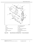
STEERING / SUSPENSION
CHAPTER 10
STEERING / SUSPENSION
GENERAL SPECIFICATIONS. . . . . . . . . . . . . . . . . . . . . . . . . . . . . . . . . . . . . . . . . . . . . 10.2
HANDLEBAR . . . . . . . . . . . . . . . . . . . . . . . . . . . . . . . . . . . . . . . . . . . . . . . . . . . . . . . . . . 10.2
REMOVAL / REPLACEMENT . . . . . . . . . . . . . . . . . . . . . . . . . . . . . . . . . . . . . . . . . . . . 10.2
INSTALLATION . . . . . . . . . . . . . . . . . . . . . . . . . . . . . . . . . . . . . . . . . . . . . . . . . . . . . . . 10.3
STEERING (NON-EPS MODELS). . . . . . . . . . . . . . . . . . . . . . . . . . . . . . . . . . . . . . . . . . 10.3
STEERING POST REMOVAL . . . . . . . . . . . . . . . . . . . . . . . . . . . . . . . . . . . . . . . . . . . . 10.3
STEERING POST INSTALLATION . . . . . . . . . . . . . . . . . . . . . . . . . . . . . . . . . . . . . . . . 10.4
STEERING EXPLODED VIEW (NON-EPS MODELS). . . . . . . . . . . . . . . . . . . . . . . . . . 10.5
STEERING (EPS MODELS) . . . . . . . . . . . . . . . . . . . . . . . . . . . . . . . . . . . . . . . . . . . . . . 10.6
UPPER STEERING POST REMOVAL / INSTALLATION . . . . . . . . . . . . . . . . . . . . . . . 10.6
EPS UNIT REMOVAL. . . . . . . . . . . . . . . . . . . . . . . . . . . . . . . . . . . . . . . . . . . . . . . . . . . 10.7
EPS UNIT INSTALLATION. . . . . . . . . . . . . . . . . . . . . . . . . . . . . . . . . . . . . . . . . . . . . . . 10.8
STEERING EXPLODED VIEW (EPS MODELS) . . . . . . . . . . . . . . . . . . . . . . . . . . . . . 10.10
STEERING TIE ROD . . . . . . . . . . . . . . . . . . . . . . . . . . . . . . . . . . . . . . . . . . . . . . . . . . . 10.11
TIE ROD / TIE ROD END REPLACEMENT . . . . . . . . . . . . . . . . . . . . . . . . . . . . . . . . . 10.11
FRONT A-ARMS . . . . . . . . . . . . . . . . . . . . . . . . . . . . . . . . . . . . . . . . . . . . . . . . . . . . . . 10.12
EXPLODED VIEW . . . . . . . . . . . . . . . . . . . . . . . . . . . . . . . . . . . . . . . . . . . . . . . . . . . . 10.12
REMOVAL / REPLACEMENT . . . . . . . . . . . . . . . . . . . . . . . . . . . . . . . . . . . . . . . . . . . 10.13
BALL JOINT SERVICE . . . . . . . . . . . . . . . . . . . . . . . . . . . . . . . . . . . . . . . . . . . . . . . . . 10.14
REMOVAL . . . . . . . . . . . . . . . . . . . . . . . . . . . . . . . . . . . . . . . . . . . . . . . . . . . . . . . . . . 10.14
INSTALLATION . . . . . . . . . . . . . . . . . . . . . . . . . . . . . . . . . . . . . . . . . . . . . . . . . . . . . . 10.15
REAR A-ARMS . . . . . . . . . . . . . . . . . . . . . . . . . . . . . . . . . . . . . . . . . . . . . . . . . . . . . . . 10.16
EXPLODED VIEW . . . . . . . . . . . . . . . . . . . . . . . . . . . . . . . . . . . . . . . . . . . . . . . . . . . . 10.16
REMOVAL / INSTALLATION . . . . . . . . . . . . . . . . . . . . . . . . . . . . . . . . . . . . . . . . . . . . 10.17
REAR STABILIZER BAR . . . . . . . . . . . . . . . . . . . . . . . . . . . . . . . . . . . . . . . . . . . . . . . . 10.18
EXPLODED VIEW . . . . . . . . . . . . . . . . . . . . . . . . . . . . . . . . . . . . . . . . . . . . . . . . . . . . 10.18
LINKAGE REMOVAL / INSTALLATION . . . . . . . . . . . . . . . . . . . . . . . . . . . . . . . . . . . . 10.19
STABILIZER BAR REMOVAL / INSTALLATION . . . . . . . . . . . . . . . . . . . . . . . . . . . . . 10.19
SHOCKS / SPRINGS. . . . . . . . . . . . . . . . . . . . . . . . . . . . . . . . . . . . . . . . . . . . . . . . . . . 10.20
EXPLODED VIEW . . . . . . . . . . . . . . . . . . . . . . . . . . . . . . . . . . . . . . . . . . . . . . . . . . . . 10.20
SHOCK REMOVAL / INSTALLATION . . . . . . . . . . . . . . . . . . . . . . . . . . . . . . . . . . . . . 10.20
SHOCK / SPRING REPLACEMENT . . . . . . . . . . . . . . . . . . . . . . . . . . . . . . . . . . . . . . 10.20
10
10.1
9923067 - 2011 Sportsman 850 Service Manual
© Copyright 2010 Polaris Sales Inc.
STEERING / SUSPENSION
GENERAL SPECIFICATIONS
HANDLEBAR
Torque Specifications
Removal / Replacement
1.
Remove the upper and lower headlight pods from the
handlebar bracket (see Chapter 9).
Item
Specification
Aluminum Wheels
75 ft. lbs. (102 Nm)
Steel Wheels
45 ft. lbs. (61 Nm)
IMPORTANT: Take note of all vent line, wire harness
and throttle cable routing for reassembly purposes.
Wheel Hub Retaining Nuts
(front and rear)
80 ft. lbs. (108 Nm)
2.
Remove the (4) fasteners retaining the handlebar bracket
and block to the steering post.
Steering Post to Bulkhead
20 ft. lbs. (27 Nm)
Steering Post to Gearcase
22 ft. lbs. (30 Nm)
Tie Rod Jam Nuts
12 ft. lbs. (16 Nm)
Tie Rod to Bearing Carrier
Tie Rod to Steering Frog
44 ft. lbs. (60 Nm)
Handlebar Block Bolts
14 ft. lbs. (19 Nm)
Shock Mounting Bolts
37 ft. lbs. (50 Nm)
Front Ball Joint Pinch Bolts
(upper and lower)
Replace fasteners if loosened
17 ft. lbs. (23 Nm)
+ 1/4 Turn or (90°)
Front A-arm to Frame Bolts
(upper and lower)
40 ft. lbs. (54 Nm)
3.
Remove the handlebar assembly from the steering post.
Rear A-arm to Frame Bolts
(upper and lower)
45 ft. lbs. (61 Nm)
Rear Upper A-Arm to
Bearing Carrier Bolts
40 ft. lbs. (54 Nm)
Rear Lower A-Arm to
Bearing Carrier Bolts
45 ft. lbs. (61 Nm)
IMPORTANT: Take care not to bend the throttle cable
or brake line while the handlebar is removed.
4.
If replacing the handlebar:
• Remove the RH and LH controls
• Remove the hand grips
CAUTION
• Pry open the upper and lower handlebar blocks and
remove them from the handlebar
Locking nuts, and bolts with pre-applied locking agent
should be replaced if removed.
The self-locking properties of the nut or bolt
are reduced or destroyed during removal
NOTE: Refer to exploded views throughout this
chapter for more torque specifications, component
identification, and location of components.
10.2
9923067 - 2011 Sportsman 850 Service Manual
© Copyright 2010 Polaris Sales Inc.
STEERING / SUSPENSION
Installation
STEERING (NON-EPS MODELS)
1.
Steering Post Removal
Locate the alignment pin on the bottom side of the upper
block. The pin should line up with the alignment hole in
the lower block and should face the front.
1.
Remove the front rack and front cover (see Chapter 9).
2.
Remove the upper and lower headlight pods from the
handlebar bracket (see Chapter 9).
IMPORTANT: Take note of all vent line, wire harness
and throttle cable routing for reassembly purposes.
2.
Position the handlebar properly and install the (4) bolts.
3.
Evenly tighten the pin side (front) bolts first. Torque the (2)
front bolts to specification.
3.
Remove the (4) fasteners retaining the handlebar bracket
and block to the steering post.
4.
Carefully remove the handlebar assembly from the steering
post and place it on the front cab.
IMPORTANT: Take care not to bend the throttle cable
or brake line while the handlebar is removed.
5.
=T
Remove the cotter pin and nut from each tie rod end at the
steering post frog.
Handlebar Bolts:
14 ft. lbs. (19 Nm)
4.
Install the rear bolts and tighten evenly. Torque the (2) rear
bolts to specification.
Cotter Pin
10
Nut
NOTE: There will be a slight gap on the backside of
the handlebar blocks after installation.
5.
If handlebar was replaced:
• Install the hand grips
• Install the RH and LH controls
6.
Rod End
Reassemble the headlight pod (see Chapter 9) .
NOTE: Make sure to route all vent lines, wire
harness and throttle cable correctly into the lower
headlight pod.
10.3
9923067 - 2011 Sportsman 850 Service Manual
© Copyright 2010 Polaris Sales Inc.
STEERING / SUSPENSION
6.
Remove the (2) bolts retaining the lower steering post
bracket to the front gearcase.
Steering Post Installation
1.
Remove
Reverse the “Steering Post Removal” procedure to
reinstall the steering post. Refer to the “Steering Exploded
View” for torque values.
NOTE: Make sure to route all vent lines, wire
harness and throttle cable correctly into the lower
headlight pod.
7.
2.
When installing the headlight into the lower pod, be sure
to install the O-rings prior to installing the headlight.
3.
Place the headlight into the lower pod mounting tabs and
press firmly until the headlight snaps into place.
4.
Lift the O-ring up and over the headlight mounting tab to
secure it.
Remove the (2) fasteners retaining the upper steering post
bushing bracket.
Adjuster
O-Ring
Remove
5.
8.
Lift the steering post assembly up from the front gearcase
and carefully remove it from the chassis.
Reinstall the adjustment screw and be sure to adjust the
upper headlight after reassembly.
NOTE: Refer to Chapter 9 when reassembling the
upper and lower headlight pods.
10.4
9923067 - 2011 Sportsman 850 Service Manual
© Copyright 2010 Polaris Sales Inc.
STEERING / SUSPENSION
Steering Exploded View (Non-EPS Models)
20 ft. lbs.
(27 Nm)
22 ft. lbs.
(30 Nm)
44 ft. lbs.
(60 Nm)
12 ft. lbs.
(16 Nm)
12 ft. lbs.
(16 Nm)
12 ft. lbs.
(16 Nm)
12 ft. lbs.
(16 Nm)
44 ft. lbs.
(60 Nm)
44 ft. lbs.
(60 Nm)
REF.
DESCRIPTION
REF.
10
DESCRIPTION
1
Tie Rod
9
Cotter Pin
2
Steering Post
10
Nut
3
Rod End, RH
11
Upper Steering Bracket
4
Jam Nut, RH
12
Upper Steering Bushing
5
Tie Rod Assembly
13
Carriage Bolt
6
Jam Nut LH
14
Nut
7
Rod End, LH
15
Bolt
8
Washer
10.5
9923067 - 2011 Sportsman 850 Service Manual
© Copyright 2010 Polaris Sales Inc.
STEERING / SUSPENSION
STEERING (EPS MODELS)
7.
Remove the (2) fasteners retaining the upper steering post
bushing bracket.
Upper Steering Post Removal
1.
Remove the front rack and front cover (see Chapter 9).
2.
Remove the upper and lower headlight pods from the
handlebar bracket (see Chapter 9).
IMPORTANT: Take note of all vent line, wire harness
and throttle cable routing for reassembly purposes.
3.
Remove the (4) fasteners retaining the handlebar bracket
and block to the steering post.
Remove
8.
Lift the upper steering post up from the power steering unit
remove it from the chassis.
Upper Steering Post Installation
4.
1.
Reverse the “Upper Steering Post Removal” procedure to
reinstall the steering post.
2.
Apply anti-seize to the shaft splines to aid assembly.
3.
Align the mark on the upper steering post (nut side) with
the skip tooth spline on the upper power steering shaft upon
installation.
4.
Carefully slide the upper steering post onto the upper power
steering shaft and install the pinch bolts.
Carefully remove the handlebar assembly from the steering
post and place it on the front cab.
IMPORTANT: Take care not to bend the throttle cable
or brake line while the handlebar is removed.
5.
Disconnect and remove the battery to access the upper
steering post pinch bolts (see Chapter 2 “Battery
Removal”).
6.
Remove the pinch bolts retaining the upper steering post to
the power steering unit.
Nut Side
Alignment
Marks
Remove
CAUTION
Striking the steering post can permanently
damage the EPS unit and cause
a Power Steering Fault.
10.6
9923067 - 2011 Sportsman 850 Service Manual
© Copyright 2010 Polaris Sales Inc.
STEERING / SUSPENSION
5.
Refer to “Steering Exploded View (EPS Models)” on page
10.12 for torque values.
EPS Unit Removal
1.
Remove the front rack or front storage box and front cover
(see Chapter 9).
2.
Remove both front mud guards, upper side panels, front cab
and right-hand footwell (see Chapter 9).
3.
Remove the fuel tank (see Chapter 3).
4.
Remove the pinch bolts retaining the upper steering post to
the power steering unit.
=T
Upper Steering Post Pinch Bolts:
15 ft. lbs. (20 Nm)
NOTE: Make sure to route all vent lines, wire
harness and throttle cable correctly into the lower
headlight pod.
6.
When installing the headlight into the lower pod, be sure
to install the O-rings prior to installing the headlight.
7.
Place the headlight into the lower pod mounting tabs and
press firmly until the headlight snaps into place.
8.
Lift the O-ring over the headlight mounting tab to secure it.
Remove
Adjuster
O-Ring
9.
5.
Disconnect the (2) electrical harnesses from the power
steering unit.
6.
Remove the (2) fasteners retaining the upper steering post
bushing bracket.
Reinstall the adjustment screw and be sure to adjust the
upper headlight after reassembly.
NOTE: Refer to Chapter 9 when reassembling the
upper and lower headlight pods.
10
Remove
7.
Lift the upper steering post up from the power steering unit.
10.7
9923067 - 2011 Sportsman 850 Service Manual
© Copyright 2010 Polaris Sales Inc.
STEERING / SUSPENSION
8.
9.
Remove the (4) mounting fasteners that retain the power
steering unit and mount plate to the frame.
EPS Unit Installation
1.
Position the vehicle so the front wheels are pointing
straight forward.
2.
Clean the lower steering post so the alignment mark is
visible. Mark the skip tooth spline on the lower power
steering shaft.
3.
Apply anti-seize to the shaft splines to aid assembly.
4.
Align the two marks and install the power steering unit.
5.
Install the (4) mount plate fasteners and torque fasteners to
specification. Refer to “Steering Exploded View (EPS
Models)”.
6.
Reconnect the (2) electrical harnesses to the power steering
unit.
Carefully lift the power steering unit up to disengage the
lower steering coupler and remove it from the chassis.
CAUTION
The 8-way connector, two rows of four pins,
does not have a channeled lock on both sides,
allowing it to be installed 180° from its intended
position. The connector will not positively
engage or snap into place while in the wrong
position, but can still be installed.
If the connector is not installed correctly, the
Power Steering Unit will not function.
10.8
9923067 - 2011 Sportsman 850 Service Manual
© Copyright 2010 Polaris Sales Inc.
STEERING / SUSPENSION
7.
Align the mark on the upper steering post (nut side) with
the skip tooth spline on the upper power steering shaft upon
installation.
9.
Install the pinch bolts and torque to specification. Refer to
“Steering Exploded View (EPS Models)”.
=T
Nut Side
Upper Steering Post Pinch Bolts:
15 ft. lbs. (20 Nm)
10. Install the fuel tank assembly, fuel line and reconnect the
fuel pump harness (see Chapter 3).
Alignment
Marks
11. Reinstall the upper steering post bushing bracket and torque
the (2) fasteners to specification.
NOTE: Apply anti-seize to the shaft splines to aid
assembly.
8.
Position the upper steering post on the shaft so the pinch
bolts are aligned with the recess in the power steering shaft.
Pinch
Bolt
20 ft. lbs. (27 Nm)
Shaft
Recess
=T
Steering Post to Bulkhead Bolts:
20 ft. lbs. (27 Nm)
12. Turn the ignition key to the “ON” position and move the
handlebar from left to right several times to ensure the
power steering doesn’t bind. If binding occurs:
Upper
Steering Post
• Loosen the (4) mounting fasteners
• Move handlebars from left to right several times to
position the power steering unit
CAUTION
Striking the steering post can permanently
damage the EPS unit and cause
a Power Steering Fault.
• Torque the (4) mounting fasteners to specification and
check the steering operation for binding again
• If no binding is present, proceed; if binding is still
present, repeat this procedure
13. Install both front mud guards, upper side panels, front cab
(if removed) and right-hand footwell (see Chapter 9).
14. Install the front cover and front rack or storage box (see
Chapter 9).
10.9
9923067 - 2011 Sportsman 850 Service Manual
© Copyright 2010 Polaris Sales Inc.
10
STEERING / SUSPENSION
Steering Exploded View (EPS Models)
20 ft. lbs.
(27 Nm)
15 ft. lbs.
(20 Nm)
22 ft. lbs.
(30 Nm)
30 ft. lbs.
(41 Nm)
44 ft. lbs.
(60 Nm)
12 ft. lbs.
(16 Nm)
22 ft. lbs.
(30 Nm)
44 ft. lbs.
(60 Nm)
12 ft. lbs.
(16 Nm)
12 ft. lbs.
(16 Nm)
12 ft. lbs.
(16 Nm)
44 ft. lbs.
(60 Nm)
44 ft. lbs.
(60 Nm)
REF.
DESCRIPTION
REF.
DESCRIPTION
1
Tie Rod Assembly
12
Upper Steering Bushing
2
Upper Steering Post
13
Carriage Bolt
3
Rod End, RH
14
Nut
4
Jam Nut, RH
15
Bolt
5
Tie Rod
16
Lower Steering Post
6
Jam Nut, LH
17
Power Steering Assembly
7
Rod End, LH
18
Power Steering Mount Plate
8
Washer
19
Front Drive Bracket, LH
9
Cotter Pin
20
Front Drive Bracket, RH
10
Nut
21
Bolt
11
Upper Steering Bracket
22
Pinch Bolt
10.10
9923067 - 2011 Sportsman 850 Service Manual
© Copyright 2010 Polaris Sales Inc.
STEERING / SUSPENSION
STEERING TIE ROD
• If replacing just the tie rod end (D), loosen the jam nut
(E) and remove the rod end
Tie Rod / Tie Rod End Replacement
• Install new rod end and torque jam nuts to specification
Use the following procedure to replace the tie rod assembly or
tie rod ends.
5.
Install the new tie rod assembly (C).
1.
6.
Install the rod ends and fasteners (B) in the proper
orientation (see illustration).
7.
Torque the tie rod end fasteners to specification and install
new cotter pins.
Elevate front of vehicle and safely support machine under
the frame area.
CAUTION
Serious injury may result if machine tips or falls.
Be sure machine is secure before beginning this
service procedure. Always wear eye protection.
2.
Remove the (4) wheel nuts and remove the front wheel(s).
3.
Remove the cotter pins (A) and tie rod end fasteners (B).
4.
Remove the tie rod assembly (C).
=T
Tie Rod End Fastener:
44 ft. lbs. (60 Nm)
8.
Install the front wheel(s) and wheel nuts. Torque wheel nuts
to specification.
=T
Wheel Nuts:
Steel Wheels: 45 ft. lbs. (61 Nm)
Aluminum Wheels: 75 ft. lbs. (102 Nm)
9.
Check wheel toe alignment and adjust as necessary (see
Chapter 2).
10
10.11
9923067 - 2011 Sportsman 850 Service Manual
© Copyright 2010 Polaris Sales Inc.
STEERING / SUSPENSION
FRONT A-ARMS
Exploded View
40 ft. lbs.
(54 Nm)
40 ft. lbs.
(54 Nm)
17 ft. lbs. (23 Nm)
+ 1/4 Turn (90°)
Always replace pinch bolt
fasteners if loosened.
REF.
REF.
DESCRIPTION
DESCRIPTION
1
Upper A-arm
8
Bushing
2
Lower A-arm
9
Pivot Shaft
3
Retaining Ring
10
Bolt
4
Ball Joint
11
Nut
5
Nut
12
CV Shield
6
Bolt (replace if loosened or removed)
13
Screw
7
Grease Fitting
14
Washer
10.12
9923067 - 2011 Sportsman 850 Service Manual
© Copyright 2010 Polaris Sales Inc.
STEERING / SUSPENSION
Removal / Replacement
WARNING
The following procedure details upper and lower A-arm
removal and replacement on one side of the vehicle.
1.
Elevate and safely support the front of the vehicle and
remove the front wheel.
2.
Remove the lower shock fastener from the upper A-arm.
The locking agent on the existing bolts was
destroyed during removal. DO NOT reuse old
hardware. Serious injury or death could result if
fasteners come loose during operation.
8.
If not replacing the A-arm, thoroughly clean the A-arm and
pivot shafts.
9.
Install new ball joint into A-arm. Refer to “Ball Joint
Replacement” section.
10. Insert new bushings and pivot shafts into the new A-arm.
11. Install new upper A-arm assembly onto vehicle frame.
Torque new bolts to 40 ft. lbs. (54 Nm).
12. Insert upper A-arm ball joint end into the bearing carrier.
Install new pinch bolt and fastener hardware. Torque new
pinch bolt to 17 ft. lbs. (23 Nm) + 1/4 Turn (90°).
13. Attach shock to A-arm with new fastener. Torque lower
shock bolt to 37 ft. lbs. (50 Nm).
3.
Remove the upper ball joint pinch bolt from the front
bearing carrier (see Figure 10-2).
14. Remove the lower ball joint pinch bolt from the front
bearing carrier (see Figure 10-2).
15. Using a soft face hammer, tap on bearing carrier to loosen
the lower A-arm ball joint end while pushing downward on
the lower A-arm. Completely remove the ball joint end
from the bearing carrier.
16. Remove the lower A-arm through-bolt fasteners and
remove the lower A-arm from the vehicle.
17. Examine A-arm bushings and pivot shafts (see “Exploded
View”). Replace if worn and discard the hardware.
18. If not replacing the A-arm, thoroughly clean the A-arm and
pivot shafts.
19. Install new ball joint into A-arm. Refer to “Ball Joint
Replacement” section.
20. Insert new bushings and pivot shafts into the new A-arm.
Figure 10-2
21. Install new lower A-arm assembly onto vehicle frame.
Torque new bolts to 40 ft. lbs. (54 Nm).
4.
Remove the brake line retainer from the upper A-arm.
5.
Using a soft face hammer, tap on bearing carrier to loosen
the upper ball joint end while lifting upward on the upper
A-arm. Completely remove the ball joint end from the
bearing carrier.
6.
Remove the upper A-arm through-bolt fasteners and
remove the A-arm from the vehicle (see “Exploded View”).
7.
Examine A-arm bushings and pivot shafts (see “Exploded
View”). Replace if worn and discard the hardware.
22. Insert lower A-arm ball joint end into the bearing carrier.
Install new pinch bolt and fastener hardware. Torque new
pinch bolt to 17 ft. lbs. (23 Nm) + 1/4 Turn (90°).
23. Grease all (4) A-arm grease fittings after reassembly.
WARNING
Upon A-arm installation completion, test vehicle
at low speeds before putting into service.
10.13
9923067 - 2011 Sportsman 850 Service Manual
© Copyright 2010 Polaris Sales Inc.
10
STEERING / SUSPENSION
BALL JOINT SERVICE
4.
Removal
IMPORTANT: Do not reuse a ball joint if it has been
removed for any reason. If removed, it must be
replaced. Use this removal procedure only when
replacing the ball joint.
1.
Use a press and correct size driver to remove the ball joint
from the A-arm.
Correct
Driver Placement
The A-arm must be removed to perform this procedure
(see “FRONT A-ARMS - Removal / Replacement”).
The driver must fit the
inside diameter of the
A-arm end.
Upper A-arm Shown
NOTE: The driver must fit the ball joint housing in
the A-arm. This will allow the ball joint to be properly
pressed out of the A-arm without damaging the Aarm.
2.
Remove the retaining ring from the ball joint.
3.
A driver must be used for the removal of the ball joint. Use
the dimensions below to fabricate or locate the correct size
driver to use in the following process.
Press out of the A-arm
in this direction
Upper A-arm Shown
Driver Dimensions
1.375 in.
(3.49 cm)
Place driver HERE
to support A-arm
3 in.
(7.62 cm)
1.75 in.
(4.45 cm)
- Outside diameter of driver cannot be any
larger than 1.75 in. (4.45 cm).
- Inside diameter cannot be any smaller than
1.375 in. (3.49 cm).
- Driver must be at least 3 in. (7.62 cm) tall.
10.14
9923067 - 2011 Sportsman 850 Service Manual
© Copyright 2010 Polaris Sales Inc.
STEERING / SUSPENSION
Installation
1.
Place the A-arm in the correct position for ball joint
installation. Face the A-arm end flat on top of the driver.
Carefully drive the ball joint into place until the ball joint
is properly seated.
Press into the A-arm
in this direction
Place driver HERE
to support A-arm
Upper A-arm Shown
2.
After the new ball joint is installed into the A-arm, install
a new retaining ring.
3.
Reinstall the A-arm (see “FRONT A-ARMS - Removal /
Replacement”).
4.
Repeat the ball joint service procedure for any additional
A-arm ball joint replacements.
10
10.15
9923067 - 2011 Sportsman 850 Service Manual
© Copyright 2010 Polaris Sales Inc.
STEERING / SUSPENSION
REAR A-ARMS
Exploded View
45 ft. lbs.
(61 Nm)
45 ft. lbs.
(61 Nm)
40 ft. lbs.
(54 Nm)
45 ft. lbs.
(61 Nm)
REF.
DESCRIPTION
REF.
DESCRIPTION
1
Bolt
9
Bolt
2
Nut
10
Pivot Shaft, Upper
3
Bushing, LCA
11
Pivot Shaft, Lower
4
Upper A-arm
12
Bushing, Lower
5
Grease Fitting
13
Pivot Tube
6
Pivot Shaft
14
Bushing, UCA
7
Bolt
15
Bolt
8
Lower A-arm
16
Bushing, Upper
10.16
9923067 - 2011 Sportsman 850 Service Manual
© Copyright 2010 Polaris Sales Inc.
STEERING / SUSPENSION
Removal
10. Remove the fastener retaining the stabilizer linkage to the
lower A-arm.
The following procedure details upper and lower A-arm
removal and replacement on one side of the vehicle.
1.
Elevate and safely support the rear of the vehicle and
remove the rear wheel.
Upper A-arm Removal
2.
Remove the through-bolt fastener attaching the upper Aarm to the bearing carrier (see “Exploded View”).
3.
Remove the through-bolt fastener attaching the upper Aarm to the frame and remove the A-arm from the vehicle.
4.
Examine A-arm and bearing carrier bushings and pivot
shafts (see “Exploded View”). Replace if worn and discard
the hardware.
WARNING
The locking agent on the existing bolts was
destroyed during removal. DO NOT reuse old
hardware. Serious injury or death could result if
fasteners come loose during operation.
11. Remove the through-bolt fasteners attaching the lower Aarm to the frame and remove the A-arm from the vehicle.
5.
If not replacing the A-arm, thoroughly clean the a-arm and
pivot shafts.
12. Examine A-arm and bearing carrier bushings and pivot
shafts (see “Exploded View”). Replace if worn and discard
the hardware.
6.
Insert new bushings and pivot shafts into the new A-arm.
Lower A-arm Removal
13. If not replacing the A-arm, thoroughly clean the a-arm and
pivot shafts. Insert new bushings and pivot shafts into the
new A-arm.
7.
Remove the through-bolt fastener attaching the lower Aarm to the bearing carrier (see “Exploded View”).
Installation
8.
Remove the lower shock fastener from the lower A-arm.
1.
Install upper and lower A-arm assemblies onto the vehicle
frame. Torque new fasteners to 45 ft. lbs. (61 Nm).
2.
Grease all (3) A-arm grease fittings after reassembly.
3.
Attach lower A-arm to bearing carrier. Torque new fastener
to 45 ft. lbs. (61 Nm).
4.
Attach upper A-arm to bearing carrier. Torque new
fasteners to 40 ft. lbs. (54 Nm). Grease both rear bearing
carrier fittings after reassembly.
5.
Route brake line on top of lower A-arm and install retainer
(if applicable).
6.
Reinstall the lower portion of the shock and lower portion
of the stabilizer linkage to the lower A-arm. Torque shock
mounting fastener (see Figure 10-19) to 37 ft. lbs. (50 Nm).
Torque linkage fastener to 17 ft. lbs. (23 Nm).
7.
Install the wheel and torque wheel nuts to specification (see
page 10.2).
WARNING
Figure 10-19
9.
Remove the brake line retainer from the lower A-arm
(if applicable).
Upon A-arm installation completion, test vehicle
at low speeds before putting into service.
10.17
9923067 - 2011 Sportsman 850 Service Manual
© Copyright 2010 Polaris Sales Inc.
10
STEERING / SUSPENSION
REAR STABILIZER BAR
Exploded View
22 ft. lbs.
(30 Nm)
17 ft. lbs.
(23 Nm)
REF.
DESCRIPTION
REF.
DESCRIPTION
1
Bolt
5
Stabilizer Bar
2
Stabilizer Bar Bracket
6
Bushing, Linkage
3
Bushing, Stabilizer Bar
7
Linkage Assembly, Stabilizer Bar
4
Nut
10.18
9923067 - 2011 Sportsman 850 Service Manual
© Copyright 2010 Polaris Sales Inc.
STEERING / SUSPENSION
Linkage Removal / Installation
1.
3.
Remove the (2) fasteners from each stabilizer bar bracket
retaining the stabilizer bar to the frame.
Remove the upper linkage bushing from each side. Using
an 5/16” open-end wrench, hold the linkage rod and
remove the lower linkage bushing.
Remove
Linkage
Remove
Hold with
5/16” wrench
XP Model Shown
4.
2.
Rotate the stabilizer bar up and remove the stabilizer
linkage from the lower A-arm. Repeat this procedure if
removing or replacing the other linkage.
3.
Reverse this procedure to reinstall the stabilizer linkage.
Refer to the “Exploded View” on the previous page for
torque values.
Remove the upper shock mounting fastener from the right
rear shock and swing the shock out from the frame.
Remove
Stabilizer Bar Removal / Installation
1.
Elevate the rear of vehicle and safely support machine
under the frame area.
CAUTION
5.
Carefully remove the stabilizer bar from the frame.
Serious injury may result if machine tips or falls.
Be sure machine is secure before beginning this
service procedure. Always wear eye protection.
2.
Remove the upper linkage bushing from each side and
rotate the stabilizer bar up.
10
Remove
XP Model Shown
6.
Inspect the stabilizer bar for straightness. Inspect the
bushings and replace if needed.. Inspect the rubber
bushings on the stabilizer linkage(s) and replace if needed.
7.
Reverse this procedure to reinstall the stabilizer bar. Refer
to the “Exploded View” on the previous page for torque
values.
10.19
9923067 - 2011 Sportsman 850 Service Manual
© Copyright 2010 Polaris Sales Inc.
STEERING / SUSPENSION
SHOCKS / SPRINGS
Exploded View
Spring
37 ft. lbs.
(50 Nm)
Spring
Retainer
Shock
Adjusting Cam
37 ft. lbs.
(50 Nm)
Shock Removal / Installation
1.
Elevate the vehicle off the ground to relieve the suspension
load.
2.
Remove the upper and lower fasteners retaining the shock
and remove the shock from the vehicle.
3.
Reverse the procedure to reinstall the shock. Torque new
fasteners to 37 ft. lbs. (50 Nm).
Shock / Spring Replacement
1.
Using a spring compressor, compress the shock spring far
enough to remove the spring retainer.
Shock Spring
Compressor Tool
2870623
2.
Remove the spring and adjusting cam from the existing
shock and install components onto the new shock.
3.
Compress the shock spring and install the spring retainer.
4.
Reinstall the shock onto the vehicle and torque new
fasteners to 37 ft. lbs. (50 Nm).
10.20
9923067 - 2011 Sportsman 850 Service Manual
© Copyright 2010 Polaris Sales Inc.