1
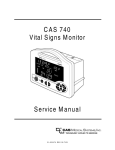
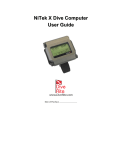
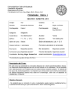
US008196581B2
(12) United States Patent
(10) Patent N0.:
(45) Date of Patent:
Bozanic et al.
(54)
MOUTHPIECE SUPPLY VALVE
(56)
(76) Inventors: Jeffrey Evan Bozanic, Fountain Valley,
OH (U S)
Notice:
Subject to any disclaimer, the term of this
patent is extended or adjusted under 35
U.S.C. 154(b) by 669 days.
12/1958
6/1981
Kline ..................... .. 128/207.16
Oswell ................... .. 128/204.26
5,127,398 A
5,746,199 A
6,681,766 B1
7/1992
5/1998
1/2004
10/2002
Stone
Bayron et a1.
Matsuoka
Chen
WO 2007/126317
11/2007
OTHER PUBLICATIONS
Author Unknown, Dive Rite 3000-2 Regulator Service Manual,
2007, 32 pages, Lamartek, Inc. D/B/A Dive Rite.
Prior Publication Data
US 2009/0320847 A1
2,865,369 A *
4,273,120 A *
FOREIGN PATENT DOCUMENTS
W0
Apr. 14, 2009
(65)
References Cited
2002/0157669 A1
(21) Appl. N0.: 12/423,7s0
(22) Filed:
Jun. 12, 2012
U.S. PATENT DOCUMENTS
CA (U S); Lars Erik Frimann, Jar
Barum (NO); Magne Tessem, Alesund
(NO); Forrest P. Gauthier, Maineville,
(*)
US 8,196,581 B2
* cited by examiner
Dec. 31, 2009
Primary Examiner * Loan Thanh
Related US. Application Data
Assistant Examiner * Peter S Vasat
(60) Provisional application No. 61/044,543, ?led on Apr.
14, 2008.
(51)
(52)
(58)
(57)
Int. Cl.
A62B 9/02
(74) Attorney, Agent, or Firm * Baker & Hostetler LLP
ABSTRACT
A mouthpiece supply valve Which may be used in connection
With a rebreather. An exemplary mouthpiece supply valve
(2006.01)
US. Cl. ....... .. 128/205.24; 128/207.16; 128/204.26;
may include a housing, an inlet mushroom valve, an outlet
128/204.27; 128/204.29; 137/81.2
mushroom valve, a supply gas regulator, an exhaust valve,
Field of Classi?cation Search ........... .. 128/205.24,
and a mode selector. An exemplary mouthpiece supply valve
may perform manual diluent valve, automatic diluent valve,
128/201.27, 201.28, 204.26, 204.27, 205.12,
128/206.15, 204.18, 205.21, 204.22, 204.29,
128/207.14, 207.16, 205.27, 205.28; 137/812,
137/384.8, 384.2; 141/293; 222/6; 251/229
See application ?le for complete search history.
102A
1025
w
overpressure relief valve, excess ?uid ejection, and bail-out
valve functions.
46 Claims, 15 Drawing Sheets
US. Patent
mNoP
Jun. 12, 2012
Sheet 1 0115
US 8,196,581 B2
US. Patent
wow
Jun. 12, 2012
Sheet 2 0115
US 8,196,581 B2
US. Patent
Jun. 12, 2012
Sheet 3 0115
US 8,196,581 B2
cor
4N/9,
US. Patent
Jun. 12, 2012
Sheet 4 0115
US 8,196,581 B2
wow
Nor
US. Patent
Jun. 12, 2012
Sheet 5 0115
US 8,196,581 B2
ow?
NE,
US. Patent
Jun. 12, 2012
Sheet 6 0115
US 8,196,581 B2
H:
NNFI.
w:
ow?m:m3m2
co?023Fw:
.vw
<Izoclmw
mm?
w:
x"@2“x4.?
US. Patent
Jun. 12, 2012
Sheet 7 0115
US 8,196,581 B2
HUZOIFMW
N:
US. Patent
Jun. 12, 2012
Sheet 8 0115
C1-C1 NOLLOEIS
NE,
QE1.625
US 8,196,581 B2
US. Patent
Jun. 12, 2012
Sheet 9 0115
US 8,196,581 B2
ow?
ow?
\- SCTIN E-E
wow wt,
US. Patent
Jun. 12, 2012
Sheet 10 0115
US 8,196,581 B2
31H NQQ
D1“
a
m
3a
US. Patent
Jun. 12, 2012
Sheet 11 0115
N?
mm?
US 8,196,581 B2
US. Patent
Jun. 12, 2012
Sheet 12 0115
US 8,196,581 B2
162
FIG12
70
158
112
US. Patent
Jun. 12, 2012
Sheet 13 0115
US 8,196,581 B2
0mm
mm?
—h
2m
09 8m50,8m
mom
wowwow
mm?
mmmN:
US. Patent
Jun. 12, 2012
Sheet 14 0115
US 8,196,581 B2
20\4_
F14IG.
200
US 8,196,581 B2
1
2
MOUTHPIECE SUPPLY VALVE
outlet tube, and the outlet valve shuts When the pres sure in the
outlet tube is greater than the pressure in the interior of the
CROSS REFERENCE TO RELATED
APPLICATION
housing, and, in the ?rst position, the overpressure valve may
be spring-biased shut. In the second position, the actuator
may be operative to maintain the inlet valve shut, the outlet
valve shut, and the overpressure valve substantially open.
This application claims the bene?t of US. Provisional
In a detailed embodiment, the inlet valve may be a mush
room valve; the outlet valve may be a mushroom valve; and
the inlet valve and the outlet valve may be mounted to an
Application No. 61/044,543, ?led Apr. 14, 2008, Which is
incorporated by reference.
axially slidable valve rod Which is operatively coupled to the
actuator, the valve rod having a ?rst position corresponding to
BACKGROUND
the ?rst position of the actuator and a second position corre
The present disclosure is direct to self-contained breathing
sponding to the second position of the actuator.
apparatus and, more particularly, to mouthpiece supply
In a detailed embodiment, the release rod may be biased
valves for use With rebreather-type self-contained breathing
from a user; store, clean, and/or re-oxygenate the gas in a
toWards its second position by a release rod spring, and the
release rod spring may be operative to prevent the release rod
from stopping in an intermediate position betWeen the ?rst
respiration loop; and then present the same respiration gas to
position and the second position.
apparatus.
Rebreather devices may collect exhaled respiration gas
the user for inhalation. Rebreather apparatus may be classi
?ed as semi-closed rebreathers (SCR) or closed circuit
rebreathers (CCR). Some rebreather devices alloW the user to
In a detailed embodiment, the valve rod may be biased
breath gasses supplied from an external source (such as a
toWards its second position corresponding With the second
position of the actuator.
In a detailed embodiment, the supply gas regulator may
compressed gas cylinder) using a bail-out valve (BOV) if the
receive pressurized gas from a compressed gas source via a
re-breather fails to perform the necessary gas renovation
functions, or When desired by the user.
The present disclosure is made in contemplation of US.
Pat. Nos. 5,127,398, 5,746,199, and 6,681,766, US. Patent
Application Publication No. 2002/0157669, and PCT WO
2007/ 126317 A1, Which are incorporated by reference into
this Background section.
20
?rst stage regulator.
25
In a detailed embodiment, the mode selector may be con
nected to the actuator by an axially slidable release rod. In a
detailed embodiment, the release rod may be axially slidable
betWeen a ?rst position corresponding to the ?rst position of
the actuator and a second position corresponding to the sec
30
SUMMARY
ond position of the actuator, and the release rod may be biased
toWards its second position corresponding With the second
position of the actuator.
In a detailed embodiment, the mode selector may be manu
Exemplary embodiments include mouthpiece supply
valves Which may be used in connection With a rebreather. An
35
exemplary mouthpiece supply valve may include a housing,
an inlet mushroom valve, an outlet mushroom valve, a supply
gas regulator, an exhaust valve, and a mode selector. An
exemplary mouthpiece supply valve may perform manual
diluent valve, automatic diluent valve, overpressure relief
valve, excess ?uid ejection, and bail-out valve functions, for
40
example.
In an aspect, a mouthpiece supply valve may include a
housing having an interior; an inlet valve arranged to selec
tively admit a respiration gas to the interior of the housing
from an inlet tube; an outlet valve arranged to selectively
45
include an automatic actuator, Which may include at least one
of a solenoid, a pneumatic actuator, a squib, a thermal reten
to an outlet tube; a mouthpiece connector ?uidicly coupled to
the interior of the housing; a supply gas regulator operative to
tion device, and a pieZo crystal actuator.
selectively admit a pressurized gas to the interior of the hous
ing When a pressure Within the interior housing is less than an
ambient pressure; an exhaust valve arranged to selectively
vent the interior of the housing When the pressure Within the
interior of the housing is greater than the ambient pres sure; an
50
overpressure valve ?uidicly interposing the interior of the
housing and the exhaust valve; a movable actuator operatively
connected to the inlet valve, the outlet valve, and the over
pressure valve; and a mode selector arranged to shift the
55
In a detailed embodiment, the inlet valve and the outlet
valve may be in ?uidic communication With a rebreather.
In a detailed embodiment, the exhaust valve may include
an exhaust valve diaphragm interposing the interior of the
housing and an ambient environment.
In a detailed embodiment, the supply gas regulator may be
operable manually via a button and automatically by a supply
gas regulator diaphragm.
actuator from a ?rst position associated With a ?rst mode to a
and the outlet valve such that the inlet valve opens When a
pressure Within the inlet tube is greater the pressure Within the
interior of the housing, the inlet valve shuts When the pres sure
in the interior of the housing is greater than the pressure
Within the inlet tube, the outlet valve opens When the pres sure
in the interior of the housing is greater than a pressure in the
tion gas, a pressure, a temperature, and a component failure.
In a detailed embodiment, a mouthpiece supply valve may
discharge the respiration gas from the interior of the housing
second position associated With a second mode. In the ?rst
position, the actuator may alloW operation of the inlet valve
ally operable by a user. In a detailed embodiment, manual
operation of the mode selector may include translation and
rotation of the mode selector. In a detailed embodiment, the
mode selector may be automatically operable in response to a
sensed condition. In a detailed embodiment, the mode selec
tor may be manually operable by the user betWeen its ?rst
position and its second position, and the mode selector may
be automatically shiftable from its ?rst position to its second
position in response to the sensed condition. In a detailed
embodiment, the sensed condition may be associated With at
least one of a partial pressure of a constituent of the respira
60
65
In a detailed embodiment, the actuator may be operatively
connected to the supply gas regulator. In a detailed embodi
ment, in the ?rst position, the actuator may be operative to
select a ?rst differential pressure setpoint for the supply gas
regulator. In a detailed embodiment, in the second position,
the actuator may be operative to select a second differential
pressure setpoint for the supply gas regulator. In a detailed
embodiment, the supply gas regulator may include a ?rst
spring arranged to bias a regulator inlet valve shut, a second
spring arranged to selectively assist the ?rst spring in biasing
US 8,196,581 B2
3
4
the regulator inlet valve shut, the ?rst differential pressure
may be associated With only the ?rst spring, and the second
differential pressure may be associated With the ?rst spring
and the second spring.
In a detailed embodiment, the release rod may be spring
biased toWards its second position and the valve rod may be
spring biased toWards its second position.
In a detailed embodiment, the release rod and the valve rod
may be arranged substantially in parallel.
In an aspect, a self-contained breathing apparatus may
include a rebreather arranged to renovate an exhaled gas
In a detailed embodiment, the exhaust valve may include
rendering it suitable for inhalation; and a mouthpiece supply
valve including a housing having an interior ?uidicly coupled
axially slidable release rod operatively coupled to the mode
an exhaust valve diaphragm arranged to alloW venting of the
interior of the housing When a pressure in the interior of the
housing is greater than an ambient pressure.
In a detailed embodiment, the second stage regulator valve
assembly may be operatively coupled to the actuator; the
selector and shiftable betWeen a ?rst position and a second
second stage regulator valve assembly may be operative to
to a mouthpiece, a mode selector mounted to the housing and
shiftable betWeen a ?rst position and a second position, an
selectively admit the pressurized gas to the interior of the
position, an actuator operatively coupled to the release rod
and shiftable betWeen a ?rst position and a second position,
the actuator including a base portion, a valve rod operatively
coupled to the actuator and shiftable betWeen a ?rst position
housing in response to a ?rst sensed pressure difference When
the actuator is in the ?rst position; and the second stage
regulator valve assembly may be operative to selectively
admit the pressurized gas to the interior of the housing in
and a second position, the valve rod having a ?rst end and a
second end, an inlet mushroom valve mounted to the ?rst end
of the valve rod, the inlet mushroom valve being arranged to
response to a second sensed pressure difference When the
20
actuator is in the second position.
In a detailed embodiment, the second stage regulator valve
assembly may include a secondary tension lever arm opera
tive to select betWeen the ?rst sensed pressure difference and
the second sensed pressure difference, and the actuator may
25
act upon the secondary tension lever arm.
alloW a respiration gas to How from the rebreather into the
interior of the housing via an inlet tube When the valve rod is
in its ?rst position and to prevent the respiration gas from
?oWing from the inlet tube into the interior of the housing
When the valve rod is in its second position, an outlet mush
room valve mounted to the second end of the valve rod, the
outlet mushroom valve being arranged to alloW a respiration
gas to How from the interior of the housing to the rebreather
via an outlet tube When the valve rod is in its ?rst position and
to prevent the respiration gas from ?oWing from the interior of
the housing into the outlet tube When the valve rod is in its
second position, an exhaust valve mounted to the housing and
arranged to vent the interior of the housing to an ambient
environment, an overpressure valve mounted to the housing
and ?uidicly interposing the interior of the housing and the
exhaust valve, the overpressure valve being spring-biased
shut When the actuator is in its ?rst position and the overpres
sure valve ?uidicly connecting the exhaust valve to the inte
rior of the housing When the actuator is in its second position,
and a second stage regulator valve assembly operatively con
nected to a source of pressurized gas and arranged to selec
30
secondary tension lever arm may selectively engage the sec
ond spring to bias the regulator inlet valve shut.
35
40
tively admit the pressurized gas to the interior of the housing,
the second stage regulator valve assembly being operative to
admit the pressurized gas to the interior of the housing in
45
response to manual actuation of a purge button and in
response to a sensed pressure difference betWeen the ambient
toWards its second position by a release rod spring, and the
release rod spring may be operative to prevent the release rod
from stopping in an intermediate position betWeen the ?rst
50
an overpressure valve selectively ?uidicly interposing the
interior of the housing and the exhaust valve; a pressurized
gas supply regulator mounted to the housing and arranged to
selectively supply a pressurized gas to the interior of the
housing; an inlet-outlet valve assembly mounted Within the
housing, the inlet-outlet valve assembly including a valve rod
valve mounted to the second end of the valve rod, and a spring
arranged to bias the valve rod toWards the second end; and an
actuator operatively coupled to the valve rod and including a
base portion, the base portion being arranged to selectively
55
position and the second position.
In a detailed embodiment, the mode selector may be auto
matically operable in response to a sensed condition. In a
detailed embodiment, the sensed condition may be associated
In a detailed embodiment, the rebreather may be a closed
circuit rebreather.
In an aspect, a mouthpiece supply valve may include a
housing including a mouthpiece and having an interior; a
one-Way exhaust valve mounted to the housing and arranged
to vent the interior of the housing to an ambient environment;
having a ?rst end and a second end, a one-Way inlet valve
mounted to the ?rst end of the valve rod, a one-Way outlet
environment and the interior of the housing.
In a detailed embodiment, the mode selector is manually
operable by a user. In a detailed embodiment, manual opera
tion of the mode selector may include translation and rotation
of the mode selector.
In a detailed embodiment, the release rod may be biased
In a detailed embodiment, the second stage regulator valve
assembly may include a regulator inlet valve ?uidicly inter
posing the source of pressurized gas and the interior of the
housing, a ?rst spring arranged to bias the regulator inlet
valve shut, and a second spring arranged to selectively bias
the regulator inlet valve shut. In a detailed embodiment, the
60
restrict and alloW gas ?oW betWeen the interior of the housing
and the exhaust valve using the overpressure valve. In a
detailed embodiment, the inlet-outlet valve assembly may be
axially slidable Within the housing betWeen a ?rst position
and a second position, the ?rst position being toWards the ?rst
end and the second position being toWards the second end. In
a detailed embodiment, the housing may include at least one
of a ring and a shoulder associated With each of the inlet valve
With at least one of a partial pressure of a constituent of the
respiration gas, a pressure, a temperature, and a component
and the outlet valve, the ring or shoulder being arranged to
hold the respective valve shut When the inlet-outlet valve
failure.
In a detailed embodiment, a mouthpiece supply valve may
assembly is in the second position.
include an automatic actuator, Which may include at least one
of a solenoid, a pneumatic actuator, a squib, a thermal reten
tion device, and a piezo crystal actuator.
65
In a detailed embodiment, a mouthpiece supply valve may
include a mode selector arranged to shift the inlet-outlet valve
assembly betWeen the ?rst position and the second position.
In a detailed embodiment, the mode selector may be arranged
US 8,196,581 B2
5
6
to simultaneously actuate the overpressure valve to restrict
and alloW gas ?oW betWeen the interior of the housing and the
exhaust valve.
In a detailed embodiment, a mouthpiece supply valve may
include a spring-biased release rod, the mode selector may be
tor to open the regulator valve When the secondary tension
piston is engaged With the regulator valve.
In a detailed embodiment, the ?rst valve actuator may
include a ?rst pivotable lever arm.
In a detailed embodiment, the second valve actuator may
include a second pivotable lever arm.
coupled to the release rod, the actuator may be coupled to the
release rod, and the valve rod may be coupled to the actuator.
In a detailed embodiment, the release rod and the valve rod
In a detailed embodiment, a regulator valve assembly may
include a diaphragm arranged to sense a differential pressure,
the diaphragm being operatively connected to the ?rst valve
may be arranged substantially in parallel.
actuator.
In a detailed embodiment, the release rod may be biased
In a detailed embodiment, the inlet ori?ce, the regulator
toWards its second position by a release rod spring, and the
release rod spring may be operative to prevent the release rod
from stopping in an intermediate position betWeen the ?rst
valve, and the secondary tension piston may be linearly
arranged.
In a detailed embodiment, a regulator valve assembly may
position and the second position.
include a valve spring adjustment boot mechanically inter
posing the second valve actuator and the secondary tension
piston. In a detailed embodiment, movement valve spring
In a detailed embodiment, the overpressure valve may be
spring-biased shut When the actuator is in the ?rst position,
and the actuator may maintain the overpressure valve open
When the actuator is in the second position.
In a detailed embodiment, the mode selector may be manu
adjustment boot in response to movement of the second valve
20
actuator is operative to engage and disengage the secondary
valve piston from the regulator valve.
ally operable to shift the inlet-outlet valve assembly betWeen
In a detailed embodiment, the ?rst valve spring may
the ?rst and second positions, and the mode selector may be
mechanically interpose the valve spring adjustment boot and
the regulator valve, and movement of the valve spring adjust
automatically operable to shift the inlet-outlet valve assembly
from the ?rst position to the second position in response to a
sensed condition. In a detailed embodiment, the sensed con
dition may be associated With at least one of a partial pressure
ment boot toWards the ori?ce may press the ?rst valve spring
25
In a detailed embodiment, a regulator valve assembly may
of a constituent of the respiration gas, a pressure, a tempera
ture, and a component failure.
In a detailed embodiment, a mouthpiece supply valve may
include an automatic actuator, Which may include at least one
of a solenoid, a pneumatic actuator, a squib, a thermal reten
include an adjustment knob threadedly engaged With the
valve spring adjustment boot, the adjustment knob being
30
operative to compress the secondary tension spring.
In an aspect, a mouthpiece supply valve control system
tion device, and a pieZo crystal actuator.
may include at least one sensor operative to produce a sensor
signal associated With a sensed condition; at least one com
puter operatively connected to the at least one sensor for
In a detailed embodiment, at least one of the inlet valve and
the outlet valve may include a mushroom-type check valve.
In a detailed embodiment, the pressurized gas supply regu
toWards the regulator valve and permits engagement of the
secondary tension piston With the regulator valve.
35
producing a computer signal associated With the sensor sig
lator may be manually actuatable via a button and automati
nal; a logic device operatively connected to the at least one
cally actuatable by a diaphragm.
computer for receiving the computer signal; and an automatic
actuator operatively connected to the logic device. The auto
matic actuator may be operatively coupled to a mouthpiece
In a detailed embodiment, the diaphragm may ?uidicly
interpose the interior of the housing and the ambient environ
ment, the diaphragm may be operatively connected to a regu
lator inlet valve, and the diaphragm may be operative to open
the regulator inlet valve When a differential pressure betWeen
the interior of the housing and the ambient environment
exceeds a ?rst setpoint When the actuator is in the ?rst posi
tion. In a detailed embodiment, the diaphragm may be opera
tive to open the regulator inlet valve When the differential
pressure betWeen the interior of the housing and the ambient
environment exceeds a second setpoint When the actuator is in
40
matic actuator may be operative to shift the mouthpiece sup
ply valve from the second mode to the ?rst mode upon receipt
of a logic device signal from the logic device.
45
an regulator valve arranged to selectively seal against the inlet
ori?ce; a valve spring arranged to bias the regulator valve into
In a detailed embodiment, the automatic actuator may
include at least one of a solenoid, a pneumatic actuator, a
squib, a thermal retention device, and a pieZo crystal actuator.
In a detailed embodiment, the sensed condition may be
the second position.
In a detailed embodiment, the inlet valve and the outlet
valve may be ?uidicly connected to a rebreather.
In an aspect, a regulator valve assembly may include an
inlet ori?ce ?uidicly connected to a source of pressurized gas;
supply valve, the mouthpiece supply valve being selectable
betWeen at least a ?rst mode and a second mode. The auto
50
associated With at least one of a partial pressure of a constitu
ent of the respiration gas, a pressure, a temperature, and a
component failure.
In a detailed embodiment, the logic device may include a
Watchdog timer, and the computer signal may include a reset
55
sealing contact With the inlet ori?ce; a ?rst valve actuator
signal When the sensor signal is associated With a normal
condition.
In a detailed embodiment, the at least one computer may
include at least tWo computers, and the at least one sensor may
include at least one sensor associated With each of the at least
operatively coupled to the regulator valve for selectively
opening the regulator valve; a secondary tension piston selec
tively engagable With the regulator valve; a secondary tension
spring arranged to bias the secondary tension piston toWard
tWo computers.
In a detailed embodiment, the at least one sensor may
the regulator valve; a second valve actuator operatively
include a plurality of sensors, the plurality of sensors being
coupled to the secondary tension piston for selectively engag
ing the secondary tension piston With the regulator valve. In a
rality of computers being operative to provide respective
associated With a respective plurality of computers, the plu
tension piston is disengaged from the regulator valve is less
computer signals to the logic device, and the logic device may
produce the logic device signal based at least partially upon
the computer signals received from the plurality of comput
than a second actuating force applied to the ?rst valve actua
ers.
detailed embodiment, a ?rst actuating force applied to the ?rst
valve actuator to open the regulator valve When the secondary
65
US 8,196,581 B2
8
7
extending out opposite sides of the main housing 100 and
coaxially aligned With each other.
In a detailed embodiment, the logic device may be pro
grammed to disregard computer signals associated With com
puters that are determined to be inoperative.
As shoWn in FIG. 14 With reference to an exemplary self
contained breathing apparatus 200, inlet tubing 104 and/or
outlet tubing 106, respectively coupled to inlet port 103 and
BRIEF DESCRIPTION OF THE DRAWINGS
outlet port 105, may connect a mouthpiece supply valve 20 to
a rebreather 202 (via inlet hose connector 104A and outlet
hose connector 106A), Which may include various gas reno
vation components operative to render an exhaled gas suitable
for inhalation.
The detailed description refers to the following ?gures in
Which:
FIG. 1 is an exploded vieW of an exemplary mouthpiece
supply valve;
FIG. 2 is a front elevation vieW of an exemplary mouth
Referring to FIGS. 1 and 14, in an exemplary embodiment,
piece supply valve;
inlet hose connector 104A and/ or outlet hose connector
FIG. 3 is a plan vieW of an exemplary mouthpiece supply
106A, respectively provided on inlet port 103 and outlet port
valve;
105, may be sealed to other components, such as inlet tubing
FIG. 4 is a left elevation vieW of an exemplary mouthpiece
104 and/or outlet tubing 106, using one or more hose connec
tor clamps 416 and/or one or more o-rings 412, 414. As
supply valve;
FIG.
FIG.
FIG.
FIG.
FIG.
FIG.
5 is cross-sectional vieW along line 5-5 in FIG. 2;
6 is a cross-sectional vieW along line 6-6 in FIG. 2;
7 is a cross-sectional vieW along line 7-7 in FIG. 4;
8 is a cross-sectional vieW along line 8-8 in FIG. 4;
9 is a cross-sectional vieW along line 9-9 in FIG. 7;
10 is a cross-sectional vieW along line 10-10 in FIG.
discussed beloW, in rebreather mode, inlet tubing 104 may
provide respiration gas to the mouthpiece for inhalation by
20
9;
FIG. 11 is a perspective vieW of an exemplary second stage
regulator valve assembly;
25
FIG. 12 is an elevation vieW of an exemplary second stage
regulator valve assembly;
inlet hose connector 104A and outlet hose connector 106A
FIG. 13 is a cross-sectional vieW along line 13-13 in FIG.
12;
FIG. 14 is a schematic diagram of an exemplary mouth
30
piece supply valve installed in an exemplary rebreather sys
tem; and
35
DETAILED DESCRIPTION
ment, a mode selector 108 (also referred to as a “BOV but
The present disclosure is direct to self-contained breathing
40
gas mixing and cleaning apparatus to a user in a rebreather
mode (also referred to as BOV mode) in Which the user is
provided With respiration gas from an external source (such as
a compressed gas cylinder) via a BOV. Exemplary embodi
ments may be useful in applications such as ?re ?ghting,
45
50
medical oxygen delivery, personnel isolation suits for haZard
ous environments, mine safety emergency gas supply sys
tems, aviation gas supply systems, underWater breathing
devices, and other applications.
Referring to FIG. 1, an exemplary mouthpiece supply
may require pulling mode selector 108 to the left (out of slot
110) and rotating it doWnWard. Similarly, a user may shift
from rebreather mode to bail out mode by rotating mode
selector 108 upWardly toWards slot 110. As discussed beloW,
a spring associated With mode selector 108 may be arranged
mode selector 108 is substantially aligned by rotation With
55
valve 20 may include a main housing 100, Which may struc
100 may include a mouthpiece connector 102, Which may
slot 110. In some exemplary embodiments, mode selector 108
may be mounted on the other side of mouthpiece supply valve
20 for operation by a user’s right hand.
In an exemplary embodiment, an external connection 112
(provided on a regulator valve assembly 158 mounted to and
extending through the valve housing 136) may be utiliZed to
60
connect mouthpiece supply valve 20 to an external source of
respiration gas, such a compressed gas cylinder 204 (see FIG.
clamping device), for example. The mouthpiece may be held
14). As Will be described in detail beloW, a purge button 118
provided on valve housing 136 and mechanically linked to
in a user’s mouth.
lever arm 160 on the regulator valve assembly 158 may be
The main housing 100 further may include a forWard open
ing port 101 for seating the valve housing 136 and its associ
mode. In bail out mode (the mode illustrated in FIGS. 2 and
3), a portion of mode selector 108 may engage slot 110
provided on the valve housing 136. A user may shift from bail
out mode to rebreather mode by extending the mode selector
out of the slot 110 and then rotating mode selector 108 doWn
Wardly. From the perspective of a user Who may be holding a
mouthpiece attached to mouthpiece connector 102 in his or
her mouth, shifting from bail out mode to rebreather mode
to pull mode selector 108 into engagement With slot 110 once
turally support various other components. The main housing
receive a compliant mouthpiece 102A (Which may be made of
silicone, rubber, or another soft material, for example) Which
may be retained by a polymer tension band 102B (or other
couple With different rebreather devices.
Referring primarily to FIGS. 1-3, in an exemplary embodi
ton”), provided on valve housing 136, may sWitch the mouth
piece supply valve 20 betWeen rebreather mode and bail out
apparatus and, more particularly, to mouthpiece supply
mode (also referred to as SCR/CCR mode). An exemplary
mouthpiece supply valve may also be operable in a bail out
may include mounting surfaces siZed to receive inlet tubing
and/or outlet tubing provided With a variety of different
rebreather devices, such as those provided by different manu
facturers. For example, inlet hose connector 104A and outlet
hose connector 106A may include mounting surfaces having
appropriate siZes, shapes, thread con?gurations, etc. to
FIG. 15 is a block diagram of an exemplary automatic
actuation system.
valves for use With rebreather-type self-contained breathing
apparatus. Exemplary embodiments may include a multi
function mouthpiece supply valve (also referred to as a dive/
surface valve (DSV)) Which provides respiration gas from a
the user, and outlet tubing 106 may receive exhaled respira
tion gas from the user via the mouthpiece. An exemplary
self-contained breathing apparatus 200 may further include a
compressed gas cylinder 204 (or other source of compressed
gas), Which may be connected to an exemplary mouthpiece
supply valve 20.
Referring back to FIG. 1, in an exemplary embodiment,
65
used to actuate the lever arm 160 on the regulator valve
ated assemblies as described beloW, and may further include
assembly 158, thus manually causing ?oW from the external
opposed, cylindrical inlet and outlet ports, 103 and 105,
source of respiration gas into the mouthpiece supply valve 20.