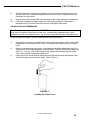
1
www.ardusmedical.com
CAS 740
Vital Signs Monitor
User’s Manual
21-02-0171 REV. 00 03/03
21-02-0171 REV. 00 03/03
THE CAS 740
VITAL SIGNS MONITOR
FEATURES
CAS 740 - 1
Non-Invasive Blood Pressure and Pulse Rate.
CAS 740 - 2
Non-Invasive Blood Pressure, Pulse Rate and Pulse Oximeter.
or
Non-Invasive Blood Pressure, Pulse Rate and Temperature.
CAS 740 - 3
Vital Signs Monitor with Non-Invasive Blood Pressure, Pulse
Rate, Pulse Oximeter and Predictive Temperature.
IMPORTANT:
This manual addresses all parameters of the CAS 740 Vital
Signs Monitor. You may have purchased a model that does
not have all the parameters referred to in the manual.
THIS MANUAL REMAINS SUITABLE FOR USE!
Please refer to sections of the manual and the Quick
Reference Guide that are applicable for the model purchased.
21-02-0171 REV. 00 03/03
In the U.S. the following Caution applies:
CAUTION:
Federal law restricts this device to sale by or on
the order of a physician or properly licensed
practitioner.
21-02-0171 REV. 00 03/03
Manufacturers Declaration of Conformity
Electronic Emissions and Immunity
The CAS 740 Monitor is intended for use in the electromagnetic environment specified below. The customer
or the user of the CAS 740 Monitor should assure it is used in such an environment.
Emissions Test
Compliance
Electromagnetic Environment
RF emissions – CISPR 11
Group 1
The CAS 740 uses RF energy only for its internal function.
Therefore, its RF emissions are very low and are not likely to
cause any interference in nearby electronic equipment.
RF emissions – CISPR 11
Class B
The CAS 740 is suitable for use in all establishments,
Harmonic emissions
including domestic establishments and those directly
Class B
IEC 61000-3-2
connected to the public low-voltage power supply network
Voltage fluctuations / flicker Complies
that supplies buildings used for domestic purposes.
emissions
Immunity Test
Electrostatic
discharge (ESD)
IEC 61000-4-2
Electrical fast
transient/burst
IEC 61000-4-4
Surge
IEC 61000-4-5
Voltage Dips, short
interruptions and
voltage variations on
power supply input
lines
IEC 61000-4-11
IEC 60601 Test
Level
+/-6 kV contact
+/-8 kV air
Compliance
Level
+/-6 kV contact
+/-8 kV air
+/-2 kV for power
supply lines
+/-1 kV for
input/output lines
+/-1 kV differential
mode
+/-2 kV common
mode
< 5% UT (>95%
dip in UT) for 0.5
cycle.
40% UT (60% dip
in UT) for 5 cycles.
70% UT (30% dip
in UT) for 25
cycles.
< 5% UT (> 95%
dip in UT) for 5
seconds.
3 A/m
+/-2 kV for power
supply lines
+/-1 kV for
input/output lines
+/-1 kV differential
mode
+/-2 kV common
mode
< 5% UT (>95% dip
in UT) for 0.5 cycle.
40% UT (60% dip
in UT) for 5 cycles.
70% UT (30% dip
in UT) for 25
cycles.
< 5% UT (> 95%
dip in UT) for 5
seconds.
Electromagnetic Environment
Guidance
Floors should be wood concrete or
ceramic tile. If floors are covered with
synthetic material, the relative humidity
should be at least 30%.
Mains power quality should be that of a
typical commercial or hospital
environment.
Mains power quality should be that of a
typical commercial or hospital
environment.
Mains power quality should be that of a
typical commercial or hospital
environment. If user of the model 740
requires continued operation during power
mains interruptions, it is recommended
that the model 740 be powered from an
uninterruptible power supply or a battery.
Power frequency
3 A/m
Power frequency magnetic fields should
(50/60 Hz)
be at levels characteristic of a typical
magnetic field
location in a typical commercial or
IEC 61000-4-8
hospital environment.
NOTE: UT is the A.C. mains voltage prior to application of the test level.
21-02-0171 REV. 00 03/03
WARRANTY POLICY
MONITORS (CAS 740)
CAS Medical Systems, Inc. warrants the monitor, when new, to be free from defects in material and
workmanship and to perform in accordance with manufacturer’s specifications for a period of two (2) years
from the date of original purchase from CAS or its authorized distributors or agents except as noted below.
The same warranty conditions are made for a period of one (1) year with respect to printers and battery and
ninety (90) days on non-disposable accessories and certain components consisting of reusable SpO2
sensors, reusable temperature probes and other accessories provided by CAS as part of the original
purchase. CAS warrants blood pressure cuffs and disposable or single-patient-use products for out-of-box
failure only. Where the accessory is not a CAS manufactured product, the manufacturers own warranty
conditions apply.
CAS reserves the right to perform warranty service operations in its own factory, at an authorized repair
facility, or at the customers’ site.
Our obligation under this warranty is limited to repairing or, at our option, replacing any defective parts or our
equipment, without charge, if such defects occur in normal service and with prompt notification.
Damage to any part through misuse, neglect, or accident, or by affixing any accessories or attachments
®
®
®
®
other than CAS, Masimo , Nellcor , Nonin , and Welch Allyn manufactured accessories or attachments,
is not covered by this warranty.
ACCESSORIES, BATTERIES, CUFFS, AND CERTAIN COMPONENTS
In all cases, policy applies from date of purchase from CAS or its authorized distributors or agents.
Accessories:
Batteries:
Cuffs (all):
External Printer:
Other Accessories:
Ninety (90) Days - Masimo, Nellcor and Nonin Sensors, Welch Allyn Temperature
Probes.
One (1) Year
Out-of-box failure only.
One (1) Year
Out-of-box failure only.
THERE ARE NO WARRANTIES, WHICH EXTEND BEYOND THOSE EXPRESSLY DESCRIBED IN THIS
AGREEMENT AND THE COMPANY MAKES NO WARRANTIES OF MERCHANTABILITY OR FITNESS
FOR A PARTICULAR PURPOSE.
21-02-0171 REV. 00 03/03
HOW TO CONTACT US
CAS Medical Systems, Inc
44 East Industrial Road
Branford, CT 06405
U.S.A.
Representative in European Union:
Mossa Consulting GmbH
Bollbrügg 22
23570 Lübeck,
Germany
Phone:
(800) 227-4414
(203) 488-6056
Phone:
+49-4502-880-557
Fax:
(203) 488-9438
Fax:
+49-4502-880-559
E-Mail:
[email protected]
[email protected]
[email protected]
E-Mail:
[email protected]
Should service be required, contact the
dealer in the country of purchase.
Web:
www.casmed.com
Copyright 2003 CAS Medical Systems, Inc.
All rights reserved. No part of this manual may be reproduced without the written permission of
CAS Medical Systems, Inc. CAS reserves the right to make changes to this manual and
improvements to the product it describes at any time without notice or obligation.
21-02-0171 REV. 00 03/03
CAS 740 Monitors
TABLE OF CONTENTS
1
INTRODUCTION AND INTENDED USE ................................................................ 1
INTRODUCTION ............................................................................................ 3
INDICATIONS FOR USE ................................................................................ 3
CONTRAINDICATIONS .................................................................................. 3
BRIEF DEVICE DESCRIPTION ...................................................................... 3
PATIENT ENVIRONMENT ............................................................................. 4
2
UNPACKING THE MONITOR .............................................................................. 7
INITIAL INSPECTION ..................................................................................... 9
MONITOR CHECKLIST .................................................................................. 9
OPTIONAL ACCESSORIES ........................................................................... 9
3
SYMBOLS ......................................................................................................... 11
4
SAFETY MEASURES, WARNINGS AND PRECAUTIONS ...................................... 17
AUTOMATIC SAFETY FEATURES ................................................................. 22
5
BLOOD PRESSURE MONITORING ..................................................................... 23
CUFF SELECTION AND APPLICATION .......................................................... 25
NIBP HOSES ............................................................................................... 27
6
PULSE OXIMETRY MONITORING ....................................................................... 29
TAKING AN SpO2 MEASUREMENT ............................................................... 31
FINGER CLIP SENSORS ........................................................................ 31
DISPOSABLE FLEX-TYPE SENSORS ..................................................... 32
MASIMO OXIMETRY ..................................................................................... 33
ATTACHING THE CABLES ...................................................................... 33
REMOVING THE INTERFACE CABLE ...................................................... 34
MASIMO MESSAGES ............................................................................ 34
NELLCOR OXIMETRY ................................................................................... 35
ATTACHMENT PROCEDURE .................................................................. 35
REMOVING THE INTERFACE CABLE ...................................................... 35
21-02-0171 REV. 00 03/03
i
CAS 740 Monitors
NONIN OXIMETRY ........................................................................................ 36
ATTACHING THE SENSOR CABLE ......................................................... 36
REMOVING THE SENSOR CABLE .......................................................... 36
7
TEMPERATURE MONITORING ........................................................................... 37
WELCH ALLYN TEMPERATURE ................................................................... 39
TAKING AN ORAL TEMPERATURE ......................................................... 39
TAKING A RECTAL TEMPERATURE ....................................................... 41
TAKING AN AXILLARY TEMPERATURE ................................................... 43
8
MONITOR OPERATION ...................................................................................... 45
FRONT PANEL ............................................................................................. 47
DIGITAL DISPLAY AND INDICATORS ...................................................... 47
FRONT PANEL CONTROLS .................................................................... 49
INFRARED DATA PORT .......................................................................... 51
REAR PANEL .............................................................................................. 52
AC/DC CONNECTOR .............................................................................. 52
FUSE COMPARTMENT .......................................................................... 52
BATTERY COMPARTMENT .................................................................... 52
LEFT SIDE PANEL ....................................................................................... 53
MAX NIBP CUFF HOSE CONNECTION .................................................... 53
SpO2 SENSOR CONNECTION ................................................................. 53
RIGHT SIDE PANEL ..................................................................................... 54
TEMPERATURE PROBE ELECTRICAL CONNECTION .............................. 54
TEMPERATURE HOLDER ....................................................................... 54
EXTERNAL DEVICE INTERFACING ......................................................... 54
MONITOR OPERATING INSTRUCTIONS ........................................................ 55
ADULT/ NEONATE OPERATING MODE ................................................... 55
TURNING THE CAS 740 MONITOR “ON” .................................................. 55
FRONT PANEL INTESITY CONTROL ....................................................... 56
DISPLAYING THE TIME .......................................................................... 56
MANUAL MODE FOR BLOOD PRESSURE DETERMINATION ................... 56
AUTOMATIC CYCLE FOR BLOOD PRESSURE DETERMINATION ............. 58
STAT MODE .......................................................................................... 58
HISTORY MODES .................................................................................. 59
EVENT HISTORY ............................................................................. 60
TREND HISTORY ............................................................................. 60
PRINT HISTORY ............................................................................... 61
CLEARING HISTORY ........................................................................ 61
REAL TIME CLOCK .......................................................................... 61
21-02-0171 REV. 00 03/03
ii
CAS 740 Monitors
PATIENT ALARM MODE ............................................................................... 62
CHANGING ALARM LIMITS ..................................................................... 62
SAVING ALARM LIMITS .......................................................................... 62
RESTORE FACTORY DEFAULTS ............................................................ 63
ALARM LIMIT VALUES ........................................................................... 63
AUDIBLE AND VISUAL INDICATORS ....................................................... 64
CLEARING ALARMS .............................................................................. 65
NIBP PATIENT ALARMS ................................................................... 65
HIGH / LOW %SpO2 ALARMS ........................................................... 65
SpO2 PULSE RATE ALARM .............................................................. 65
EQUIPMENT ALARMS ...................................................................... 65
ADJUSTING THE AUDIO ALARM VOLUME .............................................. 66
ADJUSTING THE SpO2 “BEEP” VOLUME ................................................ 66
2-MINUTE AUDIO SILENCE ..................................................................... 66
PERMANENT AUDIO ALARM SILENCE ................................................... 67
ALARM LIMITS OFF ............................................................................... 67
MONITOR CONFIGURATION ......................................................................... 68
ENTERING THE MONITOR CONFIGURATION MENU ................................ 68
SAVING YOUR CHANGES ...................................................................... 68
SOFTWARE REVISIONS ........................................................................ 69
SETTING THE LANGUAGE ..................................................................... 69
SELECTING THE PATIENT MODE ........................................................... 69
SELECTING THE TEMPERATURE SCALE ............................................... 70
AUDIO ALARMS (SILENCE/RESET PUSHBUTTON) ................................. 70
2-MINUTE AUDIO ALARM OFF .......................................................... 70
PERMANENT AUDIO ALARM OFF .................................................... 71
ALARM LIMIT OFF ............................................................................ 71
MAP VALUE ENABLE / DISABLE ........................................................... 71
SETTING THE DATE ............................................................................... 72
SETTING THE TIME ................................................................................ 72
DAYLIGHT SAVING TIME OPTION ........................................................... 72
BATTERY POWER ....................................................................................... 73
CHECKING BATTERY STATUS ............................................................... 74
AUTO OFF FEATURE ................................................................................... 74
POWER FAIL ............................................................................................... 75
USER MESSAGES ...................................................................................... 75
SpO2 USER MESSAGES ........................................................................ 75
TEMPERATURE FUNCTION USER MESSAGES ...................................... 77
ERROR MESSAGES ON THE MESSAGE WINDOW ................................ 78
9
EXTERNAL PRINTER ......................................................................................... 81
PRINTER OVERVIEW ................................................................................... 83
PRINTER CONTROLS AND INDICATORS ....................................................... 84
PRINTER OPERATIONS ............................................................................... 85
CHARGING THE PRINTER BATTERY ............................................................ 87
INSTALLING PAPER ..................................................................................... 87
REPLACING THE BATTERY PACK ................................................................ 88
INSTALLING A NEW BATTERY PACK ........................................................... 89
21-02-0171 REV. 00 03/03
iii
CAS 740 Monitors
10
EMS SWIVEL MOUNT ........................................................................................ 91
ASSEMBLING THE SWIVEL MOUNT ............................................................. 93
POLARITY OF THE POWER CABLE ............................................................. 93
11
CLEANING ......................................................................................................... 95
CLEANING OVERVIEW ................................................................................ 97
THE MONITOR ............................................................................................. 97
THE DISPLAY .............................................................................................. 98
CUFFS AND SENSORS ................................................................................ 98
PNEUMATIC TUBING .................................................................................... 98
PRINTER ..................................................................................................... 98
12
MAINTENANCE .................................................................................................. 99
MAINTENANCE INTERVALS ......................................................................... 101
TEST MODE ................................................................................................ 101
EXIT THE TEST MODE .................................................................................. 101
LED CHECK ................................................................................................. 102
CALIBRATION CHECK .................................................................................. 102
SYSTEM PRESSURE ............................................................................. 102
OVERPRESSURE .................................................................................. 103
PNEUMATIC PRESSURE CHECK ........................................................... 103
PLUG TUBE ..................................................................................... 103
500 ML PRESSURE CHECK ............................................................. 104
TEMPERATURE CALIBRATION CHECK ......................................................... 104
OXIMETRY CALIBRATION CHECK ................................................................. 105
REPLACING THE MONITOR BATTERY .......................................................... 105
REMOVING THE BATTERY ..................................................................... 106
INSTALLING THE BATTERY .................................................................... 106
CHANGING THE FUSES ............................................................................... 107
STORAGE ................................................................................................... 107
13
EXTERNAL DEVICE INTERFACING ..................................................................... 109
OVERVIEW ................................................................................................. 111
RS232 ......................................................................................................... 111
NURSE CALL INTERFACE ............................................................................ 111
21-02-0171 REV. 00 03/03
iv
CAS 740 Monitors
14
ACCESSORIES .................................................................................................. 113
BLOOD PRESSURE CUFFS ......................................................................... 115
INFLATION HOSES ...................................................................................... 115
OXIMETRY ................................................................................................... 116
MASIMO ................................................................................................ 116
NELLCOR .............................................................................................. 116
NONIN ................................................................................................... 116
TEMPERATURE ........................................................................................... 117
WELCH ALLYN ...................................................................................... 117
OTHER ACCESSORIES ................................................................................ 117
15
GLOSSARY ....................................................................................................... 119
16
SPECIFICATIONS .............................................................................................. 123
CAS 740 MONITOR PURCHASING RECORD ......................................................................... 130
21-02-0171 REV. 00 03/03
v
CAS 740 Monitors
FIGURES
Figure 1 ...................................................................................................................................... 4
Patient Environment
Figure 2 ...................................................................................................................................... 25
Cuff Application
Figure 3 ...................................................................................................................................... 26
Cuff Positioning
Figure 4 ...................................................................................................................................... 31
SpO2 Finger Clip Sensor Application
Figure 5 ...................................................................................................................................... 32
Flex – Type Adult Application
Figure 6 ...................................................................................................................................... 32
Flex – Type Infant Application
Figure 7 ...................................................................................................................................... 32
Flex – Type Neonatal Application
Figure 8 ...................................................................................................................................... 39
Loading the Probe Cover
Figure 9 ...................................................................................................................................... 40
Location of Sublingual Pockets
Figure 10..................................................................................................................................... 42
Loading the Probe Cover
Figure 11..................................................................................................................................... 43
Loading the Probe Cover
Figure 12..................................................................................................................................... 47
Front Panel View
Figure 13..................................................................................................................................... 49
Front Panel Controls
Figure 14..................................................................................................................................... 52
Rear Panel View
Figure 15..................................................................................................................................... 53
Left Side Panel View
Figure 16..................................................................................................................................... 54
Right Side Panel View
21-02-0171 REV. 00 03/03
vi
CAS 740 Monitors
Figure 17..................................................................................................................................... 84
Printer Controls and Indicators
Figure 18..................................................................................................................................... 86
Sample Printouts
Figure 19..................................................................................................................................... 87
Paper Installation
Figure 20..................................................................................................................................... 88
Opening the Battery Door
Figure 21..................................................................................................................................... 89
Installing the New Battery
Figure 22..................................................................................................................................... 106
Removing the Monitor Battery Pack
Figure 23..................................................................................................................................... 112
DB9 Male Connector Pin Layout
21-02-0171 REV. 00 03/03
vii
CAS 740 Monitors
TABLES
Table 1........................................................................................................................................ 5
Parts of the System
Table 2........................................................................................................................................ 27
Neonatal Cuff Size Selection
Table 3........................................................................................................................................ 27
Adult – Infant Cuff Size Selection
Table 4........................................................................................................................................ 57
Selectable Initial Inflation Pressures
Table 5........................................................................................................................................ 63
Default Alarm Values
Table 6........................................................................................................................................ 64
Audible and Visual Indicators
Table 7........................................................................................................................................ 69
Software Revisions
Table 8........................................................................................................................................ 77
Temperature Error Codes
Table 9........................................................................................................................................ 78
Error Messages on the Message Window
Table 10...................................................................................................................................... 112
DB9 Pin Out
Table 11...................................................................................................................................... 118
Monitor Configurations
21-02-0171 REV. 00 03/03
viii
CAS 740 Monitors
Section
1
Introduction and Intended Use
21-02-0171 REV. 00 03/03
1
CAS 740 Monitors
21-02-0171 REV. 00 03/03
2
CAS 740 Monitors
INTRODUCTION AND INTENDED USE
INTRODUCTION
The CAS 740 Monitor is multi parameter monitor measuring blood pressure, oxygen saturation and
temperature. Non-invasive blood pressure is measured using the oscillometric technique determining
systolic, diastolic, mean arterial pressure and pulse rate. The pulse oximeter function continuously
monitors and displays values for functional arterial hemoglobin saturation and a pulse rate. Temperature is
obtained in the normal (predictive) mode in as little as four (4) seconds. A monitoring mode is available for
taking axillary temperatures.
INDICATIONS FOR USE
The CAS 740 Monitor is a portable device intended to be used by trained clinicians for multi-parameter vital
signs monitoring of neonatal, pediatric and adult patients in health care bedside applications as well as for
intra-facility or inter-facility and EMS transport. Parameters displayed are the non-invasive blood pressure
(systolic, diastolic and mean arterial pressure), pulse rate, functional oxygen saturation of arterial
hemoglobin (%SpO2) and temperature.
CONTRAINDICATIONS
•
•
•
•
Oral and Rectal Temperature measurements are not intended for neonatal use.
Reusable SpO2 sensor is contraindicated for use for prolonged periods of use. It is not intended for
long term monitoring. It must be removed and repositioned every four (4) hours and if indicated by
circulatory condition or skin integrity, reapplied to a different monitoring site.
Disposable SpO2 sensors are contraindicated for patients that exhibit allergic reactions to adhesive
tape. The sensors must be removed and repositioned every eight (8) hours and if indicated by
circulatory condition or skin integrity, reapplied to a different monitoring site.
No other contraindications are known at this time.
BRIEF DEVICE DESCRIPTION
The CAS 740 Monitor is compact, lightweight and portable, allowing it to be easily carried and used in a
variety of clinical settings. The monitor is powered by AC Line Power, +12 VDC or by a Nickel Metal
Hydride (NiMH) rechargeable battery pack. The internal battery pack charges when the monitor is plugged
into a power source (AC Line Power or +12 VDC). The CAS 740 Monitor can be set to operate in one of
eight (8) different languages: English, German, French, Italian, Spanish, Dutch, Swedish or Portuguese.
The message window can display various system alarm messages. These messages direct the user to
check conditions such as the battery state, air leaks and measurement problems. The message window
also displays the operational mode of the monitor (automatic or manual).
The non-invasive blood pressure (NIBP) parameter automatically inflates an occluding cuff and, using the
oscillometric measurement technique, determines systolic, diastolic and mean arterial pressure and pulse
rate. Measurement results along with operator prompts and error messages are displayed on the front
panel. The frequency of NIBP determination can be selected by the operator in varied times between one
and ninety minutes. The auto and manual operating modes cover a variety of clinical uses.
21-02-0171 REV. 00 03/03
3
CAS 740 Monitors
The pulse oximeter parameter (%SpO2) determines arterial oxyhemoglobin saturation by measuring the
absorption of red and infrared light passing through the tissue. Changes in absorption caused by pulsations
of blood in the vascular bed are used to determine arterial saturation and pulse rate. The oximeter requires
no routine calibration or maintenance.
Oxygen saturation and heart rate are displayed on light emitting diode (LED) digital displays. On each
detected pulse, the perfusion LED does indicate patient perfusion signals. This bar graph gives the user a
pulse-by-pulse visual indication of waveform signal quality. An audio “beep” can be enabled that is
generated each time the SpO2 sensor detects a pulse.
NOTE:
The bar graph is not proportional to the pulse volume.
The temperature parameter has the capability of taking temperature in either normal (predictive) or monitor
mode. In the normal mode, the thermometer’s microprocessor “predicts” body temperature in about four (4)
seconds for oral temperatures, about ten (10) seconds for axillary temperatures and in about fifteen (15)
seconds for rectal temperatures.
Monitor mode is normally used for longer term monitoring and when difficult situations prevent accurate
temperature from being taken in the predictive mode. In monitoring mode, the probe must be in contact with
tissue for at least three (3) minutes for accurate oral / rectal temperature measurement and five (5) minutes
for accurate axillary temperature measurement.
The default setting used by the CAS 740 Monitor for temperature determinations is the normal (predictive)
mode.
NOTE:
Axillary temperature readings may only be taken in the Neonate monitoring mode.
PATIENT ENVIRONMENT
The CAS 740 Monitor has been tested with specific parts of the “system” used within the Patient
Environment. Figure 1, defines the Patient Environment.
FIGURE 1
Patient Environment
21-02-0171 REV. 00 03/03
4
CAS 740 Monitors
The parts of the CAS 740 Monitor “system” that can be used in the Patient Environment are defined as;
The CAS 740 Monitor
Appropriate Accessories, listed in the ACCESSORIES section of this User’s Manual
Line Cord
Optional RS232 / Nurse Call Option
Citizen CMP-10 Mobile Printer
RS232 Interconnect Cable (supplied with printer)
AC Adapter / Charger, Model TRC-09-1100-M from Group West (supplied with printer)
TABLE 1
Parts of the System
21-02-0171 REV. 00 03/03
5
CAS 740 Monitors
21-02-0171 REV. 00 03/03
6
CAS 740 Monitors
Section
2
Unpacking the Monitor
21-02-0171 REV. 00 03/03
7
CAS 740 Monitors
21-02-0171 REV. 00 03/03
8
CAS 740 Monitors
UNPACKING THE MONITOR
INITIAL INSPECTION
Before unpacking the monitor, inspect the packaging for damage. If there are any signs of damage to the
package, a claim should be filed immediately with the shipping agent. It is the receiver's responsibility to
notify the carrier's local office to arrange for the pickup of the damaged items. Save the damaged shipping
carton as evidence.
Contact your distributor, CAS sales representative, or call CAS Medical Systems, Inc. to report external
damage and to arrange for repair or replacement of damaged equipment.
The shipping carton should contain the items listed below. Unpack the monitor and account for each item.
Inspect each item for signs of external damage, dents, cracks, scratches, etc. If an item is missing or
damaged, contact your distributor, CAS sales representative, or CAS Medical Systems, Inc.
Record the monitor model, serial number and date of purchase at the back of this manual.
MONITOR CHECKLIST
Qty
Description
1
1
1
1
1
1
1
1
CAS 740 Monitor
AC Power Cord or DC Power Cord – depending on model ordered
Ten (10) Foot Coiled Inflation Hose
Tuff-Cuff® Blood Pressure Cuffs, Adult
Tuff-Cuff® Blood Pressure Cuffs, Child
SpO2 Interconnect Cable - For models with SpO2 installed.(*)
SpO2 Finger Sensor - For models with SpO2 installed.(*)
SureTemp® Oral Probe and a box of Probe Covers - For models with Temperature installed.
1
1
P9 Calibration Kit (includes T - connector with tubing and male luer plug)
CAS 740 Monitor User’s Manual
(*) CAS 740 Monitors configured with Nonin SpO2, ship with a 2-meter sensor/cable assembly.
Read this Manual completely before using this equipment.
OPTIONAL ACCESSORIES
The CAS 740 Monitor is available with several mounting configurations to fit your needs. They consist of:
Swiveled Hard Mount
Carrying Case
GCX Roll Stand and Basket
Universal Mount
Refer to Section 14, ACCESSORIES for part number information. Contact CAS Medical Systems’
Customer Service Department or your local distributor for more information.
21-02-0171 REV. 00 03/03
9
CAS 740 Monitors
21-02-0171 REV. 00 03/03
10
CAS 740 Monitors
Section
3
Symbols
21-02-0171 REV. 00 03/03
11
CAS 740 Monitors
21-02-0171 REV. 00 03/03
12
CAS 740 Monitors
SYMBOLS
Units may display the following symbols:
Alternating Current
CAUTION: Before using, read instructions included.
Signifies the device has meet all essential requirements of
European Medical Device Directive 93/42/EEC.
Class II equipment (if applicable)
The CAS 740 Monitor is normally a Class I device.
The CAS 740 Monitor becomes a Class II device when it is mounted in an
ambulance and connected to a DC power source (740M).
Symbol used on the rear panel of the CAS 740M, to indicate the
polarity of the DC power input.
Direct Current
Indicates protection against the effects of the discharge of a cardiac
defibrillator. Patient connections are Type BF and protected against
defibrillation.
NIBP Hose and Cuff Connector
SpO2
Pulse Oximeter Probe Connector
21-02-0171 REV. 00 03/03
13
CAS 740 Monitors
SYMBOLS
(CONT.)
Two way Communication Port
RS232 and Nurse Call Interface Connector
Temperature Probe Connector
These symbols appear on the front panel in the place of text.
ON/OFF (STANDBY) – Turns “ON” the Monitor’s display.
NOTE: At a later date symbol will become
SILENCE/RESET
START/STAT
CANCEL
CYCLE TIME
HISTORY
21-02-0171 REV. 00 03/03
14
CAS 740 Monitors
SYMBOLS
(CONT.)
VOLUME
ALARM LIMITS
ARROW UP
ARROW DOWN
Bar graph display of SpO2 signal strength.
Ì
BPM
Pulse Rate Display
ADULT
A lighted LED used to indicate NIBP operating in Adult Mode.
NEO
A lighted LED used to indicate NIBP operating in Neonatal Mode.
TEMP
A lighted LED used to indicate the Temperature Option is installed.
A tri-colored LED used to indicate the status of the monitors power
source.
21-02-0171 REV. 00 03/03
15
CAS 740 Monitors
SYMBOLS
(CONT.)
These symbols appear on the battery pack in place of text.
Recycling suggested (see General Notes).
Located on the Smart Pack batteries, a set of four
(4) LEDs used to indicate the approximate amount of
charge remaining in the battery pack. See Page 74,
CHECKING BATTERY STATUS for more
information.
These symbols appear on the packaging in place of text.
Symbol used to indicate where Relative Humidity information
concerning storage and transport can be located.
Symbol used to indicate the minimum and maximum storage
and transport Temperatures.
This symbol appears on the printer in place of text.
WARNING: Before removing, read instructions in Section 9.
21-02-0171 REV. 00 03/03
16
CAS 740 Monitors
Section
4
Safety Measures, Warnings
and Precautions
21-02-0171 REV. 00 03/03
17
CAS 740 Monitors
21-02-0171 REV. 00 03/03
18
CAS 740 Monitors
SAFETY MEASURES AND WARNINGS
WARNING:
DO NOT use this instrument for any purpose other than specified in this manual. Doing so will invalidate the
monitor’s warranty.
DO NOT connect more than one (1) patient to the monitor.
The position of subject, physiological condition, and other factors affect the readings. Blood pressure and
pulse can fluctuate greatly between measurements; the monitor cannot alert the user to changes in vital
signs occurring between measurement cycles.
The power supply, located inside the CAS 740 Monitor, must be protectively grounded. If the integrity of the
protective earth conductor (ground) in the AC Line cord is in doubt, the CAS 740 Monitor must be operated
from its internal electrical power source (battery) only.
DO NOT, under any circumstances, perform any testing or maintenance on the monitor or power cord while
the unit is being used to monitor a patient. Unplug the power cord before cleaning or servicing the monitor.
The operator should not perform any servicing except as specifically stated in this manual.
DO NOT touch part of non-medical electrical equipment in the patient environment after removal of covers,
connectors etc… without the use of a tool which operate at voltages not exceeding 25 VAC or 60 VDC and
the patient at the same time.
DO NOT use any accessory if you notice any sign of damage. Contact CAS Medical Systems for
assistance.
Equipment not suitable for use in the presence of a FLAMMABLE ANESTHETIC MIXTURE with AIR or with
OXYGEN or NITROUS OXIDE.
Equipment is not intended to be used in Oxygen Enriched Atmospheres.
DO NOT gas sterilize or autoclave the monitor.
DO NOT apply the blood pressure cuff on an extremity being used for an intravenous infusion.
DO NOT place liquids on top of the monitor. Do not immerse the monitor or power cord in water or any
liquid. If unit is accidentally wetted it should be thoroughly dried. The rear cover can be removed by a
qualified service technician to verify absence of water.
During use and testing, single-use disposable temperature probe covers will limit patient crosscontamination and ensure the safety of the patient, user and device. The use of any other probe covers or
failure to use a probe cover may produce temperature errors and will invalidate the monitor’s warranty.
A pulse oximeter should be considered an early warning device. As a trend toward patient deoxygenation is
indicated, blood samples should be analyzed by a laboratory co-oximeter to completely understand the
patient’s condition.
21-02-0171 REV. 00 03/03
19
CAS 740 Monitors
WARNING:
Accurate oxygen saturation measurements cannot be obtained when the oximeter is not measuring the
pulse properly. If the perfusion LED is erratic or the PULSE RATE display is erratic or inaccurate, first
examine the patient for any sign of distress and only then re-examine sensor placement.
CAUTION:
As with any non-invasive oscillometric blood pressure monitor, the accuracy of the measurements obtained
may be adversely affected by the presence of agents, which alter the patient’s cardiovascular system.
DO NOT operate the monitor unless it has been properly calibrated. Inaccurate blood pressure readings
may result. A calibration check is recommended once every year. A pneumatic check is recommended
once every six (6) months.
DO NOT alter the monitor's air hose. CAS Medical Systems cannot ensure proper monitor performance if
the tubing is altered. Modification of the air hose will void the warranty. Avoid compression or restriction of
pressure tubes.
DO NOT use the monitor during an MRI scan. The monitor may affect the MRI image, and the MRI unit may
affect the accuracy of blood pressure measurements.
The monitor does not operate effectively if a patient is having seizure activity or is connected to a heart/lung
machine.
In shock conditions, the low amplitude of the blood pressure waveform may make it difficult for the monitor
to accurately determine the systolic and diastolic pressures.
When a patient is experiencing arrhythmias during a measurement, the accuracy of the pulse determination
may be affected or the time needed to complete a measurement may be extended. The monitor will not
make a determination beyond 120 seconds.
If the cuff is applied on a limb being used for oxygen saturation monitoring %SpO2 results will be altered
during each blood pressure measurement due to the occlusion of blood flow.
Inspect the monitor, air hose and sensors for any damage prior to operation. If any damage is noted, the
monitor should not be used until it has been serviced. The monitor should be repaired only by personnel
authorized to do so by CAS Medical Systems, Inc.
Use only CAS Medical Systems approved accessories and sensors to preserve the integrity, accuracy and
the electromagnetic compatibility of the monitor.
Consult a physician for interpretation of blood pressure measurements.
The oximeter is factory calibrated to determine the percentage of arterial oxygen saturation of functional
hemoglobin. Significant levels of dysfunctional hemoglobins such as carboxyhemoglobin or methemoglobin
may affect the accuracy of the measurement.
Cardiogreen and other intravascular dyes, depending on the concentration, may affect the accuracy of the
oximeter measurement.
21-02-0171 REV. 00 03/03
20
CAS 740 Monitors
CAUTION:
Some sensors may not be appropriate for a particular patient. If at least ten seconds of one bar pulses
cannot be observed for a given sensor, change sensor location or sensor type until this condition is
achieved.
If the monitor fails to respond, DO NOT use it until the situation has been corrected by qualified personnel.
ACCIDENTAL SPILLS - In the event that fluids are accidentally spilled on the monitor, take the monitor out
of operation and inspect for damage.
ELECTRICAL SHOCK - To reduce the risk of electrical shock, do not remove the back cover. Refer all
servicing to qualified personnel.
ELECTROMAGNETIC COMPATIBILITY (EMC) - The equipment needs special precautions regarding EMC.
Be aware that strong electromagnetic fields may interfere with monitor operation. Interference prevents the
clear reception of signals by the monitor. If the hospital is close to a strong transmitter such as TV, AM, or
FM radio, police or fire stations, a HAM radio operator, an airport, or cellular phone, their signals could be
picked up as signals by the monitor. If you feel interference is affecting the monitor, contact your CAS
Medical Systems representative to check the monitor in your environment.
ELECTROSURGERY - Measurements may be affected in the presence of strong electromagnetic sources
such as electro surgery equipment.
GROUNDING - Do not defeat the three-wire grounding feature of the power cord by means of adaptors, plug
modifications, or other methods. Do not use extension cords of any type. Do not connect the monitor to an
electrical outlet controlled by a wall switch or dimmer.
INTERFACING OTHER EQUIPMENT - Monitoring equipment must be interfaced with other types of medical
equipment by qualified biomedical engineering personnel. Be certain to consult manufacturers’
specifications to maintain safe operation.
LEAKAGE CURRENT TEST - The interconnection of auxiliary equipment with this device may increase the
total leakage current. When interfacing with other equipment, a test for leakage current must be performed
by a qualified biomedical engineering personnel before using with patients. Serious injury or death could
result if the leakage current exceeds applicable standards. The use of accessory equipment not complying
with the equivalent safety requirements of this equipment may lead to a reduced level of safety of the
resulting system. Consideration relating to the choice shall include: use of the accessory in the patient
vicinity; and evidence that the safety certification of the accessory has been performed in accordance with
the appropriate IEC 601.1 and/or IEC 601.1.1 harmonized national standard.
STACKING - Where monitor is used adjacent to or stacked with other equipment, the monitor should be
observed to verify normal operation in the configuration in which it will be used.
Read this manual carefully before patient use of the monitor.
21-02-0171 REV. 00 03/03
21
CAS 740 Monitors
GENERAL NOTES:
If the accuracy of any measurement does not seem reasonable, first check the patient’s vital signs by
alternate means and then check the CAS 740 Monitor for proper functioning.
The monitor is suitable for use in the presence of electro surgery.
The monitor is suitable to be connected to public AC mains power.
There are no known risks with common disposal of equipment or accessories; however, the disposing of
accessories should follow in accordance with local hospital policies. The user should ensure these policies
do not conflict with any local, state or federal guidelines.
The CAS 740 Monitor is not “Category AP or APG Equipment”.
The CAS 740 Monitor is for “Continuous Operation”.
The CAS 740 Monitor applied parts are “Type BF Defibrillation Proof”.
The CAS 740 Monitor provides only “ordinary protection from ingress to moisture”.
To completely remove AC Mains power from the CAS 740 Monitor, the power cord must be disconnected
from the monitor.
AUTOMATIC SAFETY FEATURES
The monitor has been designed to promote patient safety. The maximum amount of time allowed to
complete a blood pressure measurement is 120 seconds in adult mode and 90 seconds in neonate mode. If
the measurement has not been completed within that time, the cuff is deflated automatically and a message
is displayed indicating the problem.
To prevent exposure of the extremity to an inordinately high pressure, the cuff is deflated automatically when
the pressure in the system is greater than 290 mmHg in the adult mode or 145 mmHg in the neonatal mode.
In the event of a microprocessor failure, the cuff will be deflated automatically within ten (10) seconds.
All equipment parts are protected against the effects of the discharge of a defibrillator. No separate actions
are required when using this equipment with a defibrillator.
Should the AC or DC power be interrupted coming into the monitor, the monitor automatically runs off
battery power. An indication of this would be a change in color of the Battery Power Visual Indicator LED
from Green to either Orange or Red.
Whenever the power is disconnected from the monitor and the monitor is not allowed to shut down in an
orderly fashion, the monitor, when re-powered alerts the user. Refer to Page 75, POWER FAIL for more
information.
CAUTION:
Regardless of these safety features, always be sure to check that there are no signs of prolonged
impairment of circulation and that the monitor is functioning properly.
21-02-0171 REV. 00 03/03
22
CAS 740 Monitors
Section
5
Blood Pressure Monitoring
21-02-0171 REV. 00 03/03
23
CAS 740 Monitors
21-02-0171 REV. 00 03/03
24
CAS 740 Monitors
BLOOD PRESSURE MONITORING
CUFF SELECTION AND APPLICATION
The use of properly designed and sized cuffs is essential for the accurate measurement of blood pressure.
Safe-CuffTM adult single patient use cuffs or Tuff-Cuff® reusable cuffs or Pedisphyg® are recommended for
use with the CAS 740 Monitor.
The widest cuff that can be placed around the upper arm or thigh should be used. A cuff that is too small for
the arm will not supply sufficient pressure to the artery. This can cause an erroneously high blood pressure
reading. Substitution of a cuff different from that supplied might result in a measurement error.
NOTE:
Overlapping the cuff will not affect the measurement results.
FIGURE 2
Cuff Application
As an example, the end of the Tuff-Cuff is marked with a white arrow. To insure that the proper cuff size has
been selected, wrap the cuff around the patient’s extremity, the arrow should point between the white
markings on the cuff.
Verify the hook and loop sections of the cuff are fully engaged when it is wrapped around the limb.
Measurements made above the level of the heart will give reduced blood pressure readings while
measurements made below the heart level will give increased readings. These errors are mainly due to the
weight of the blood.
The CAS cuff is very easy to use because it does not require exact placement over the brachial artery. The
fully encircling bladder ensures that the artery is properly compressed every time.
21-02-0171 REV. 00 03/03
25
CAS 740 Monitors
Do not compress the cuff or the cuff hose. The hose must not be kinked or pinched. It can be placed in
any position.
For best results, a cuff should be wrapped for a snug fit and the limb should be positioned to be at heart
level.
Do not wrap a cuff over the patient’s clothing; inaccuracies could be introduced into the measurement.
FIGURE 3
Cuff Positioning
NOTE:
Remember that there may be a marked difference between readings taken from the left and the right arms.
Be consistent with each patient.
WARNING:
The cuff should NOT be applied on a limb being used for an intravenous infusion. Do not place the cuff on
any extremity being used for SpO2 monitoring.
WARNING:
When monitoring over an extended period of time, or at frequent intervals, periodically observe the patient’s
limb to make sure that the circulation is not impaired for a prolonged period of time.
21-02-0171 REV. 00 03/03
26
CAS 740 Monitors
Use the following tables as a guide to select the correct size cuff.
Pedisphyg Neonatal Cuffs
Cuff Model Number
Bladder Size
(Width)
Limb Circumference
Range
C26
2.5 cm (1.0 in.)
5.0 - 9.0 cm (2.0 - 3.5 in.)
C39
3.0 cm (1.2 in.)
6.5 - 11.5 cm (2.5 - 4.5 in.)
C412
4.0 cm (1.6 in.)
9.0 - 14.5 cm (3.5 - 5.7 in.)
C515
5.0 cm (2.0 in.)
11.0 - 17.75 cm (4.3 - 7.0 in.)
TABLE 2
Neonatal Cuff Size Selection
Adult and Infant Cuffs
Patient Application
Bladder Size
(Width)
Limb Circumference
Range
Infant
6 cm (2.4 in.)
11 - 19 cm (4.3 - 7.5 in.)
Small Child
7 cm (2.8 in.)
15 - 24 cm (6.0 - 9.4 in.)
Child
9 cm (3.5 in.)
18 - 28 cm (7.1 - 11.0 in.)
Small Adult
12 cm (4.7 in.)
18 - 28 cm (7.1 - 11.0 in.)
Adult
14 cm (5.5 in.)
24 - 37 cm (9.4 - 14.6 in.)
Large Adult
16 cm (6.3 in.)
26 - 42 cm (10.2 - 16.5 in.)
TABLE 3
Adult - Infant Cuff Size Selection
NIBP HOSES
CAS Medical offers two (2) NIBP Inflation Hoses.
For Adult and Pediatric patient monitoring using the ADULT NIBP mode and Cuffs, the coiled ten (10) foot
NIBP hose (CAS p/n 01-02-0131) is recommended.
For Neonatal and Infant patient monitoring using the NEO NIBP mode and Neonatal cuffs, the Neonatal six
(6) foot NIBP hose (CAS p/n 01-02-0185) is recommended.
See Section 14, ACCESSORIES for CAS Medical Systems cuff size and part number information.
NOTE:
Avoid compression or restriction of NIBP hoses.
21-02-0171 REV. 00 03/03
27
CAS 740 Monitors
21-02-0171 REV. 00 03/03
28
CAS 740 Monitors
Section
6
Pulse Oximetry Monitoring
21-02-0171 REV. 00 03/03
29
CAS 740 Monitors
21-02-0171 REV. 00 03/03
30
CAS 740 Monitors
PULSE OXIMETRY MONITORING
The CAS 740 Monitor features a wide variety of SpO2 technology that is ideal for every
application.
TAKING A SpO2 MEASUREMENT
IMPORTANT:
Prior to patient monitoring, ensure the monitor is configured to the appropriate patient mode – Neonate or
Adult.
The following is a general procedure for taking a SpO2 measurement:
1)
Select a sensor based on the patient size and monitoring conditions and properly attach the sensor
to the patient.
FINGER CLIP SENSORS
The finger clip sensor is designed for spot check monitoring of pediatric and adult patients or continuous
monitoring of less than 30 minutes, where patient movement is not expected, and the patient’s finger is
large enough for the sensor to be attached securely.
NOTE:
If patient movement is occurring or the finger size is inappropriate, select a different sensor that is
appropriate for the patient and the monitoring environment.
FIGURE 4
SpO2 Finger Clip Sensor Application
Insert the finger (preferably left or right index finger) completely into the sensor. Place the sensor with the
LEDs positioned on the nail side. The thumb is specifically not recommended for use with the finger clip
sensor.
21-02-0171 REV. 00 03/03
31
CAS 740 Monitors
DISPOSABLE FLEX - TYPE SENSORS
These types of sensors are designed for patients as a single patient use sensor and is intended for use
where moderate patient movement is expected or cross contamination is possible.
FIGURE 5
Flex - Type Adult Application
Adult and Pediatric: The preferred application site is the index finger, however, other fingers or toes may be
used where the tissue thickness is between 5 and 17 millimeters.
FIGURE 6
Flex - Type Infant Application
Infant: The preferred application site is the large toe of infants greater than 2 kilograms in weight.
FIGURE 7
Flex – Type Neonatal Application
Neonatal: The preferred application site is on the foot close to the toes for infants less than 2 kilograms in
weight.
21-02-0171 REV. 00 03/03
32
CAS 740 Monitors
NOTE:
For best results, secure the sensor cable independently from the sensor, preferably around the base of the
finger. Tape may be used to secure the cable to the patient. Make sure that the tape being used does not
restrict the blood flow.
2)
Once the sensor has been attached to the patient and to the monitor, the SpO2 signal bar graph will
illuminate and indicate the relative signal strength and signal quality at the sensor site. Wait for the
monitor to determine the initial %SpO2 and Pulse Rate values. When the values have been
determined, they will be displayed in their respective %SpO2 and ÌBPM front panel LED display
windows.
NOTE:
Inspect the pulse oximeter site every 2 to 4 hours or per hospital protocol. If there is any skin irritation
caused by the sensor, remove the sensor and apply it to a different location.
3)
When SpO2 monitoring is completed, remove the sensor from the patient.
When the probe is removed from the patient, the message “Prb OFF” appears in the Message Window and
an audible alarm sounds, indicating a connection has been lost.
Press the SILENCE/RESET pushbutton. The monitor silences the audible alarm tone, but the message
remains.
NOTE:
If either the 2-Minute Audio Off or Permanent Audio Off is enabled, no audio will be heard but a visual
message will appear in the Message Window.
MASIMO OXIMETER (if so equipped)
The CAS 740 Monitor can be equipped to use SpO2 sensors manufactured by Masimo. No other
manufacturer’s sensors should be used.
NOTE:
CAS 740 Monitors equipped with Masimo oximetry will have the Masimo SET logo next to the SpO2
connector.
ATTACHING THE CABLES
1)
Select and apply a sensor that is the appropriate size for the patient’s digit or extremity, according
to the instructions provided by Masimo.
2)
Orient the connecting tab of the sensor so that the shiny contacts are pointed up. Mate the logo on
the sensor to the logo on the patient cable.
3)
Insert the tab of the sensor into the patient cable connector until there is a tactile or audible “click”
connection. Verify a secure connection and gently tug on the patient cable connector.
4)
Plug the Interface Cable into the SpO2 connector on the side panel of the monitor. The connector is
shaped like a “D”. Line up the “D” on the Interface Cable with the “D” on the receptacle. Push the
cable in until you hear an audible “click”.
21-02-0171 REV. 00 03/03
33
CAS 740 Monitors
5)
Press the POWER pushbutton to turn “ON” the monitor.
6)
Check the Alarm Limits and configure them appropriately for the patient. Refer to Page 62,
PATIENT ALARM MODE for more information.
REMOVING THE INTERFACE CABLE
When SpO2 monitoring is not required, disconnect the Interface Cable by squeezing the grey tabs with your
thumb and index finger while pulling the connector away from the monitor.
NOTE:
To avoid damage to the Interface Cable, always hold it by the connector rather than the cable when
connecting or disconnecting either end.
When the probe is disconnected from the monitor, the message “No Probe” appears in the Message
Window and an audible alarm sounds indicating a connection has been broken. Press the
SILENCE/RESET pushbutton to silence the visual and audible alarm.
NOTE:
If either the 2-Minute Audio Off or Permanent Audio Off is enabled, no audio will be heard but a visual
message will appear in the Message Window.
See Section 14, ACCESSORIES for Masimo oximeter probe types and part number information. Consult
instructions enclosed with each sensor for proper application.
MASIMO MESSAGES
When the message “Low Perf” or “Low Sig” appear in the Message Window, and the monitor is displaying
valid %SpO2 numerics, no audible alarm will be heard.
When the message “Low Perf” or “Low Sig” appear in the Message Window, and the monitor is not
displaying valid %SpO2 numerics, an audible alarm will be heard. Press the SILENCE/RESET pushbutton.
The monitor silences the audio alarm tone, but the message remains.
21-02-0171 REV. 00 03/03
34
CAS 740 Monitors
NELLCOR OXIMETER (if so equipped)
The CAS 740 Monitor can be equipped to use Nellcor OxiMax™sensors. No other manufacturer’s sensors
should be used.
NOTE:
CAS 740 Monitors equipped with Nellcor oximetry will have the Nellcor OxiMax logo next to the SpO2
connector.
ATTACHMENT PROCEDURE
1) Select and apply a sensor that is the appropriate size for the patient’s digit or extremity, according to
the instructions provided by Nellcor.
2) Connect the sensor assembly to the Interface Cable:
a) Place the plastic hinged cover in the unlocked position (perpendicular to the connector).
b) Connect the sensor assembly to the Interface Cable.
c) Lock the plastic hinged cover to prevent accidental cable disconnection.
3) Plug the Interface Cable into the SpO2 connector on the side panel of the monitor. The connector is
shaped like a “D”. Line up the “D” on the Interface Cable with the “D” on the receptacle. Push the
cable in until you hear an audible “click”.
4) Press the POWER pushbutton to turn “ON” the monitor.
5) Check the Alarm Limits and configure them appropriately for the patient. Refer to Page 62, PATIENT
ALARM MODE for more information.
REMOVING THE INTERFACE CABLE
When SpO2 monitoring is not required, disconnect the Interface Cable by squeezing the grey tabs with your
thumb and index finger while pulling the connector away from the monitor.
NOTE:
To avoid damage to the Interface Cable, always hold it by the connector rather than the cable when
connecting or disconnecting either end.
When the probe is disconnected from the monitor, the message “No Probe” appears in the Message
Window and an audible alarm sounds indicating a connection has been broken. Press the
SILENCE/RESET pushbutton to silence the visual and audible alarm.
NOTE:
If either the 2-Minute Audio Off or Permanent Audio Off is enabled, no audio will be heard but a visual
message will appear in the Message Window.
See Section 14, ACCESSORIES for Nellcor oximeter probe types and part number information. Consult
instructions enclosed with each sensor for proper application.
21-02-0171 REV. 00 03/03
35
CAS 740 Monitors
NONIN OXIMETER (if so equipped)
The CAS 740 Monitor can be equipped to use SpO2 sensors manufactured by Nonin. No other
manufacturer’s sensors should be used.
NOTE:
CAS 740 Monitors equipped with Nonin oximetry will have the Nonin logo next to the SpO2 connector.
ATTACHING THE SENSOR CABLE
1)
Select and apply a sensor that is the appropriate size for the patient’s digit or extremity, according
to the instructions provided by Nonin.
2)
Plug the sensor assembly into the SpO2 connector on the side panel of the monitor. The connector
is shaped like a “D”. Line up the “D” on the sensor cable with the “D” on the receptacle. Push the
connector in completely.
3)
Press the POWER pushbutton to turn “ON” the monitor.
4)
Check the Alarm Limits and configure them appropriately for the patient. Refer to Page 62,
PATIENT ALARM MODE for more information.
REMOVING THE SENSOR CABLE
When SpO2 monitoring is not required, disconnect the Sensor Cable by carefully removing the connector
from the SpO2 input receptacle.
NOTE:
To avoid damage to the Sensor Cable, always hold it by the connector rather than the cable when
connecting or disconnecting either end.
When the probe is disconnected from the monitor, the message “No Probe” appears in the Message
Window and an audible alarm sounds indicating a connection has been broken. Press the
SILENCE/RESET pushbutton to silence the visual and audible alarm.
NOTE:
If either the 2-Minute Audio Off or Permanent Audio Off is enabled, no audio will be heard but a visual
message will appear in the Message Window.
Refer to Section 14, ACCESSORIES for Nonin oximeter probe types and part number information. Consult
instructions enclosed with each sensor for proper application.
21-02-0171 REV. 00 03/03
36
CAS 740 Monitors
Section
7
Temperature Monitoring
21-02-0171 REV. 00 03/03
37
CAS 740 Monitors
21-02-0171 REV. 00 03/03
38
CAS 740 Monitors
TEMPERATURE MONITORING
WELCH ALLYN TEMPERATURE (if so equipped)
WARNING:
During use, single-use disposable temperature probe covers supplied by CAS Medical Systems or Welch
Allyn will limit patient cross-contamination. The use of any other probe cover or the failure to use a probe
cover may produce temperature errors and will invalidate the monitor’s warranty. Temperature probe covers
are required to ensure the safety of the patient and user.
TAKING AN ORAL TEMPERATURE
CAUTION:
Never use the Temperature Probe without a probe cover. Accurate oral temperatures can only be obtained
by using the blue temperature probe. The use of the wrong probe will produce temperature errors.
To take an oral temperature (in either Predictive or Monitor mode) follow this procedure:
1)
Insure that the oral probe is connected to the monitor. The oral probe has a BLUE probe cover
ejection button.
2)
Remove the probe from the probe holder. A short self-test mode will be initiated where every LED
segment in the TEMP display window are illuminated briefly. Following this self-test the display will
show “OrL”. The “OrL” in the TEMP display window indicates that the oral algorithm will be used to
take a predictive temperature measurement.
3)
Load a probe cover onto the probe by holding the probe collar with the thumb and forefinger, being
careful not to hold or press the ejection button. Refer to Figure 8.
FIGURE 8
Loading the Probe Cover.
21-02-0171 REV. 00 03/03
39
CAS 740 Monitors
4)
When a double dash “– –“ appears in the TEMP display window, the temperature sensor is ready
to take a measurement. To take a normal predictive temperature, simply insert the probe tip gently
into the patient’s slightly opened mouth. Carefully slide the probe under the tongue on either side of
the mouth to reach the sublingual pocket. Refer to Figure 9.
To take a direct read temperature (monitor mode) wait 1 minute until a temperature value appears in
the TEMP display. The decimal point associated with the temperature value will flash at a rate of
one (1) second “ON” and one (1) second “OFF” as a reminder that you are in monitor mode. Insert
the probe tip into the patient’s mouth as described above.
NOTE:
Accurate temperatures can only be obtained in this location. Temperatures in other mouth locations can vary by
as much as 2°F or 1°C.
Sublingual Pockets
FIGURE 9
Location of Sublingual Pockets
5)
The probe should be held by the clinician during the entire temperature measurement process to
insure the probe tip maintains tissue contact.
6)
During the predictive temperature measurement cycle, “walking” segments will appear in the TEMP
display window indicating that a predictive measurement is in process.
7)
When the final temperature has been reached, the temperature value will be displayed in the TEMP
display window and an audible tone will be generated. The time of the measurement and the
measured temperature will be stored in the monitor’s history memory.
21-02-0171 REV. 00 03/03
40
CAS 740 Monitors
NOTE:
If the probe tip did not maintain tissue contact during the entire predictive measurement, the final
temperature displayed in the TEMP display window will flash. If this occurs it is recommended that a new
temperature be taken. Depress the SILENCE/RESET pushbutton or after waiting for two (2) minutes the
monitor will automatically blank the display.
8)
After the temperature measurement is complete, remove the probe from the patient’s mouth and
eject the probe cover by firmly pressing the ejection button on the probe. Properly dispose of the
used probe cover per protocol.
9)
Insert the probe into the probe holder before attempting to take another temperature measurement.
10)
Following a completed temperature measurement, the current temperature measurement is
displayed for thirty (30) seconds after which time the TEMP display will go blank.
TAKING A RECTAL TEMPERATURE
CAUTION:
Never use the Temperature Probe without a probe cover. Accurate rectal temperatures can only be obtained
by using the red temperature probe. The use of the wrong probe will produce temperature errors.
To take a rectal temperature, follow this procedure:
1)
Insure that the rectal probe is connected to the monitor. The rectal probe has a RED probe cover
ejection button.
2)
Remove the probe from the probe holder. A short self-test mode will be initiated where every LED
segment in the TEMP display window are illuminated briefly. Following this self-test the display will
show “rEC”. The “rEC” in the TEMP display window indicates that the rectal algorithm will be used
to take a predictive temperature measurement.
3)
Load a probe cover onto the probe by holding the probe collar with the thumb and forefinger, being
careful not to hold or press the ejection button. Refer to Figure 10.
21-02-0171 REV. 00 03/03
41
CAS 740 Monitors
FIGURE 10
Loading the Probe Cover
4)
When a double dash “– –“ appears in the TEMP display window, the temperature sensor is ready
to take a measurement. To take a normal predictive temperature, separate the buttocks with one
hand. Apply a thin coat of water-based lubricant when necessary. Using the other hand, gently
insert the probe ONLY 1cm (3/8 inch ONLY) inside the rectal sphincter.
To take a direct read temperature (monitor mode) wait 1 minute until a temperature value appears in
the TEMP display. The decimal point associated with the temperature value will flash at a rate of
one (1) second “ON” and one (1) second “OFF” as a reminder that you are in monitor mode. Insert
the probe tip into the patient’s rectal sphincter as described above.
WARNING:
Extreme caution should be used to avoid risk of bowel perforation in children.
5)
Tilt the probe to insure good tissue contact and continue to keep the buttocks separated while the
measurement is in process.
6)
During the predictive temperature measurement cycle, “walking” segments will appear in the TEMP
display window indicating that a predictive measurement is in process.
7)
When the final temperature has been reached, the temperature value will be displayed in the TEMP
display window and an audible tone will be generated. The time of the measurement and the
measured temperature will be stored in the monitor’s history memory.
NOTE:
If the probe tip did not maintain tissue contact during the entire predictive measurement, the final
temperature displayed in the TEMP display window will flash. If this occurs it is recommended that a new
temperature be taken. Depress the SILENCE/RESET pushbutton or after waiting for two (2) minutes the
monitor will automatically blank the display.
21-02-0171 REV. 00 03/03
42
CAS 740 Monitors
8)
After the temperature measurement is complete, remove the probe from the patient’s rectum and
eject the probe cover by firmly pressing the ejection button on the probe. Properly dispose of the
used probe cover per protocol.
9)
Insert the probe into the probe holder before attempting to take another temperature measurement.
10)
Following a completed temperature measurement, the current temperature measurement is
displayed for thirty (30) seconds after which time the TEMP display will go blank.
TAKING AN AXILLARY TEMPERATURE
CAUTION:
Never use the Temperature Probe without a probe cover. Accurate axillary temperatures can only be
obtained by using the blue temperature probe. The use of the wrong probe will produce temperature errors.
To take an axillary temperature in Normal (Predictive) mode follow this procedure:
1)
Insure that the oral probe is connected to the monitor and that the monitor is in NEO mode (Axillary
temperatures can only be taken in NEO mode). The oral probe has a BLUE probe cover ejection
button.
2)
Remove the probe from the probe holder. A short self-test mode will be initiated where every LED
segment in the TEMP display window are illuminated briefly. Following this self-test the display will
show “ALy”. The “ALy” in the TEMP display window indicates that the axillary algorithm will be
used to take a predictive temperature measurement.
3)
Load a probe cover onto the probe by holding the probe collar with the thumb and forefinger, being
careful not to hold or press the ejection button. Refer to Figure 11.
FIGURE 11
Loading the Probe Cover
21-02-0171 REV. 00 03/03
43
CAS 740 Monitors
When a double dash “– –“ appears in the TEMP display window the temperature sensor is ready to take a
measurement. To take a normal predictive temperature, simply place the probe as high as possible in the
axilla. Do not allow the probe tip to come into contact with the patient until it is deliberately placed in the
measurement site.
4)
Be sure that the probe tip is completely surrounded by axillary tissue. Clothing or any other
material touching the probe tip may cause inaccurate readings.
5)
Place the arm close to the patient’s side. Hold the arm in this position without movement of the
arm or probe during the measurement cycle.
6)
During the predictive temperature measurement cycle, “walking” segments will appear in the TEMP
display window, indicating that a predictive measurement is in process.
7)
When the final temperature has been reached, the temperature value will be displayed in TEMP
display window and an audible tone will be generated. The time of the measurement and the
measured temperature will be stored in the monitor’s history memory.
NOTE:
If the probe tip did not maintain tissue contact during the entire predictive measurement, the final
temperature displayed in the TEMP display window will flash. If this occurs it is recommended that a new
temperature be taken. Depress the SILENCE/RESET pushbutton or after waiting for two (2) minutes the
monitor will automatically blank the display.
8)
After the temperature measurement is complete, remove the probe from the patient’s axilla and
eject the probe cover by firmly pressing the ejection button on the probe. Properly dispose of the
used probe cover per protocol.
9)
Insert the probe into the probe holder before attempting to take another temperature measurement.
10)
Following a completed temperature measurement, the current temperature measurement is
displayed for thirty (30) seconds after which time the TEMP display will go blank.
See Section 14, ACCESSORIES for Welch Allyn temperature probe types and part number information.
Consult instructions enclosed with each probe for proper application.
21-02-0171 REV. 00 03/03
44
CAS 740 Monitors
Section
8
Monitor Operation
21-02-0171 REV. 00 03/03
45
CAS 740 Monitors
21-02-0171 REV. 00 03/03
46
CAS 740 Monitors
MONITOR OPERATION
FRONT PANEL
FIGURE 12
Front Panel View
DIGITAL DISPLAY AND INDICATORS
SYSTOLIC mmHg
Red colored LEDs indicate the Systolic pressure measurement in mmHg.
DIASTOLIC mmHg
Red colored LEDs indicate the Diastolic pressure measurement in mmHg.
MAP mmHg
Red colored LEDs indicate the Mean Arterial Pressure in mmHg (if
enabled).
TEMP
A Yellow LED indicator with Red colored LEDs indicates temperature value
(if installed).
21-02-0171 REV. 00 03/03
47
CAS 740 Monitors
% SpO2
Green colored LEDs indicates the %SpO2 value (if installed).
Ì BPM
Red colored LEDs indicate the Pulse Rate in BPM (beats per minute).
Green colored LEDs provide a visual indication of the SpO2 signal strength
in a bar graph form (if installed).
ADULT
A yellow LED indicator used to inform the user that the NIBP is operating
in the Adult Mode.
NEO
A yellow LED indicator used to inform the user that the NIBP is operating
in the Neonatal Mode.
TEMP
A yellow LED indicator used to inform the user that the Temperature Option is
installed.
Message Window area used to display various messages that aid the user
in monitor operation.
A tri-colored visual indicator used to display the status of the power source
and battery condition.
•
•
•
GREEN = Charging
ORANGE = In Use on Battery
RED = Battery Low or Dead Battery
A visual indicator used along with the SILENCE/RESET pushbutton to display
the status of the Audio Alarms.
21-02-0171 REV. 00 03/03
48
CAS 740 Monitors
FRONT PANEL CONTROLS
FIGURE 13
Front Panel Controls
ON/OFF (STANDBY):
Turns “ON” the Monitor’s display.
NOTE: At a later date symbol will become
SILENCE/RESET:
Used to enable and disable the two (2) Minute Audio Off or Permanent
Audio Off feature. Refer to Page 62, PATIENT ALARM MODE for more
information.
Allows the user to clear NIBP, SpO2 and Temperature messages from the
front panel display.
21-02-0171 REV. 00 03/03
49
CAS 740 Monitors
START/STAT:
START:
Initiates a blood pressure measurement in the Manual Mode or begins the
selected Automatic Cycle.
STAT:
Starts a series of NIBP measurements (depress and hold for two (2)
seconds). Continues for five minutes.
CANCEL:
Cancels any active blood pressure function and immediately deflates the cuff.
Also used to cancel out of a menu and return to “Ready”.
CYCLE
TIME:
Allows the user to select a time interval for Automatic blood
pressure measurement.
Automatic measurement cycles of 1, 2, 3, 4, 5, 10, 15, 30, 60, or 90
minutes may be chosen.
Also used to read the monitor’s current time (depress and hold for two (2)
seconds).
HISTORY:
Allows the user to review stored patient readings. Refer to Page 59,
HISTORY MODES for more information.
AUDIO:
Used to set the volume level of the Alarms and the SpO2 Beep (if SpO2
installed). Use the Up and Down Arrows to change.
Also used to adjust the brightness of the front panel displays (depress and
hold for two (2) seconds).
ALARM
LIMITS:
Allows the user to enter and set the monitor’s Alarm Limits.
21-02-0171 REV. 00 03/03
50
CAS 740 Monitors
ARROW
UP:
Allows forward Adjustment (Auto Cycle, History, Inflation Pressure,
Limits and Monitor Configuration).
Depress to cycle through menu selections or depress and hold for quicker
advance.
ARROW
DOWN:
Allows backwards Adjustment (Auto Cycle, History, Inflation
Pressure, Limits and Monitor Configuration).
Depress to cycle through menu selections or depress and hold for quicker
advance.
NEXT
The HISTORY and AUDIO pushbutton keys have been programmed to
allow the user to advance forward to the next selection in the Monitor
Configuration menu.
PREVIOUS
The CYCLE TIME and ALARM LIMITS pushbutton keys have been
programmed to allow the user to advance backwards to the previous
selection in the Monitor Configuration menu.
INFRARED (IrDA) DATA PORT
An Infrared (IrDA) output port, located on the bottom panel of the monitor’s front cover, is available to print
the NIBP, %SpO2 and Temperature History data to the optional external printer or other data collection
device(s).
21-02-0171 REV. 00 03/03
51
CAS 740 Monitors
REAR PANEL
FIGURE 14
Rear Panel View
CAS 740 Monitor without Temperature Module
AC / DC CONNECTION
Receptacle for the AC power cord when the CAS 740 Monitor is purchased with an AC Line Power option
and built–in battery.
When the CAS 740 Monitor is purchased as an EMS monitor equipped with a Swivel Mount, the ambulance
DC power cord is attached here.
FUSE COMPARTMENT
When the CAS 740 Monitor is purchased for AC Line power, the power input receptacle incorporates dual
fuses located in the hot and neutral lines.
BATTERY COMPARTMENT
The CAS 740 Monitor is equipped with a 7.2 Volt, 3700 mAhr battery pack that, when fully charged, is
capable of taking 100 NIBP readings when the monitor is set in the 5-minute Automatic Mode.
NOTE:
The serial number label is located on the bottom of the monitor.
21-02-0171 REV. 00 03/03
52
CAS 740 Monitors
LEFT SIDE VIEW
FIGURE 15
Left Side Panel View
CUFF HOSE CONNECTION
The inflation hose is connected to the monitor where the MAXNIBP logo is located as shown in Figure 15.
The hose must be connected to the cuff prior to use.
NOTE:
An optional six (6) foot inflation hose is available when monitoring in the NEO mode. Refer to Section 14,
ACCESSORIES for part number information.
SpO2 SENSOR CONNECTION (if equipped)
Connect the sensor cable in this receptacle for SpO2 monitoring.
21-02-0171 REV. 00 03/03
53
CAS 740 Monitors
RIGHT SIDE VIEW
FIGURE 16
Right Side Panel View
CAS 740 Monitor with Temperature and RS232 Module Installed
TEMPERATURE PROBE ELECTRICAL CONNECTION (if equipped)
Connect the Temperature cable in this receptacle for Temperature monitoring. Leave the probe connection
in place. The Temperature function is OFF until the probe is removed from the holder. Refer to Section 7,
TEMPERATURE MONITORING for more information.
TEMPERATURE HOLDER (if equipped)
Store the Temperature Probe and Temperature Probe Covers in their holder locations when it is not in use.
EXTERNAL DEVICE INTERFACING
The CAS 740 Monitor is available with a combined optional DB9 RS232 output and Nurse Call Interface.
The RS232 output maybe used to interface to the Citizen CMP-10 Mobile Printer or another serial printing
device.
Refer to Section 13, EXTERNAL DEVICE INTERFACING for more information.
21-02-0171 REV. 00 03/03
54
CAS 740 Monitors
MONITOR OPERATING INSTRUCTIONS
ADULT/ NEONATE OPERATING MODE
NIBP and Temperature functions are affected by changing between ADULT and NEONATE operating modes.
IMPORTANT:
Prior to patient monitoring, ensure the monitor is configured to the appropriate patient mode – Neonate or
Adult. Refer to Page 69, SELECTING THE PATIENT MODE for more information.
Once power has been applied, a visual indicator, located on the front panel of the monitor, indicates the
current operating mode.
TURNING THE CAS 740 MONITOR “ON”
Press the ON/OFF (STANDBY) pushbutton on the front panel to turn the monitor “ON”.
Upon applying power to the monitor, the CAS 740 Monitor displays a one (1) second Configuration Setup
Test and conducts a four (4) second electronic Power On Self-Test (POST) to ensure that its internal
circuits are functioning properly.
NOTE:
The user should use the Power On Self Test as a verification tool that all front panel visual indicators and the
audio are functioning properly.
The one (1) second Configuration Setup Test is a visual indication of the CAS 740 Monitor’s current
configuration. It consists of the monitor’s Model number and a description of its power source (740 or
740M), an Installed Parameter Code (1, 2, 3) and a one (1) or two (2) character module configuration code.
As an example, upon power-up the CAS 740 Monitor displays: 740-2MS.
•
•
•
The first set of characters indicates the Model number and the source of its power supply (740 =
Internal/AC Line Power or 740M = DC connection).
The second character (2) describes how many parameters are installed in the monitor. The monitor
in our example is configured for NIBP and SpO2. Installed Parameter Codes include;
Ø (1) = NIBP; (2) = NIBP and SpO2 or Temperature; (3) = NIBP, SpO2 and Temperature
The third set of characters (MS) describes the type of module installed. The monitor in our example
is configured for Masimo oximeter. Configuration Codes are;
Ø MS = Masimo; NL = Nellcor; NN = Nonin; T = Temperature
21-02-0171 REV. 00 03/03
55
CAS 740 Monitors
The four (4) second Power On Self-Test consists of:
•
•
•
•
All equipped parameter segments are lit for one (1) second.
All High Alarm Values are displayed for one (1) second in their corresponding numeric display
window and an audible tone is emitted from the monitor’s internal speaker. The Message Window
indicates “HI LIMS”.
All Low Alarm Values are displayed for one (1) second in their corresponding numeric display
window and an audible tone is emitted from the monitor’s internal speaker. The Message Window
indicates “LO LIMS”.
The monitor’s current time is displayed for 1 second.
Once the test is completed, the monitor indicates that it is “Ready” for use.
FRONT PANEL INTENSITY CONTROL
The CAS 740 Monitor utilizes Super Bright LED displays in its front panel for better viewing in a variety of
environments. If the displays are too bright or should the need come to operate the monitor in a dimly lit
environment, the monitor incorporates a user selectable Intensity Control.
Depress and Hold the front panel AUDIO pushbutton for two (2) seconds. The monitor’s front panel LED
displays will toggle from their bright to their dim intensity level.
Continue to depress the AUDIO pushbutton and every two (2) seconds the monitor’s front panel LED
displays will toggle; dim to bright, bright to dim etc. Release the AUDIO pushbutton and select the intensity
level required. The CAS 740 Monitor remembers this setting and will power-up the next time to the intensity
level selected.
DISPLAYING THE TIME
The CAS 740 Monitor can be used to display the current Time of day (as set by the user) at any time.
Depress and Hold the CYCLE TIME pushbutton for two (2) seconds.
The monitor displays the Time, in 24 Hr. format in the Message Window for as long as the pushbutton is
depressed.
MANUAL MODE FOR BLOOD PRESSURE DETERMINATION
Select and apply the appropriate sized cuff for the patient being monitored to the extremity. Refer to
Section 5, BLOOD PRESSURE MONITORING for more information.
Connect the cuff to the end of the monitor tubing. Connect the monitor tubing to the NIBP connector,
located on the left side of the monitor.
To select one of the Initial Inflation Pressures shown in TABLE 4, press either the ARROW UP or the
ARROW DOWN pushbutton or accept the default Initial Inflation Pressure of 150 mmHg (Adult) or 85 mmHg
(Neonate).
21-02-0171 REV. 00 03/03
56
CAS 740 Monitors
CAUTION:
When measuring blood pressure on a Pediatric patient, using the ADULT mode, it is recommended that the
Initial Inflation Pressure be set to a lower value of 120 mmHg.
ADULT MODE
NEONATE MODE
200 mmHg
180 mmHg
160 mmHg
150 mmHg
140 mmHg
120 mmHg
100 mmHg
120 mmHg
100 mmHg
85 mmHg
80 mmHg
60 mmHg
TABLE 4
Selectable Initial Inflation Pressures
IMPORTANT:
It is important that the patient be kept still during a measurement. Make every attempt to alleviate fear,
anxiety and pain.
Press the START pushbutton to begin a measurement. For the first measurement the monitor will inflate to
the default setting or the Initial Inflation Pressure selected.
The monitor’s front panel NIBP displays will indicate all dashes “ “ while the measurement is in progress
and the Message Window displays the Inflation Pressure in the format “Meas XXX”, where “XXX” is the
pressure value. For subsequent measurements, the monitor will inflate approximately 30 mmHg higher than
the previously determined Systolic pressure.
The measurement typically takes less than 30 seconds to complete. In no case will the cuff remain
pressurized for more than 120 seconds for Adult/Pediatric patients and no more than 90 seconds for
Neonates.
When the measurement is completed, the cuff will automatically deflate and the monitor will display the
Systolic, Diastolic, MAP (if enabled), and Pulse Rate values on the front panel displays. The Message
Window displays a time stamp of the NIBP measurement in the format “BP HH:MM”. Where “HH” is the
hour and “MM” is the minute of the measurement taken.
NOTE:
If SpO2 is active, the Pulse Rate value will be determined from the SpO2 measurement.
Press the CANCEL pushbutton, at any time, to stop a measurement and deflate the cuff during the
measurement process. The monitor’s front panel NIBP displays will indicate all dashes “ “ and the
Message Window returns to “Ready”.
The CANCEL pushbutton can be depressed after a measurement is taken to clear the current reading from
the displays. The monitor’s front panel NIBP displays will indicate all dashes “ “ and the Message Window
returns to “Ready”.
NOTE:
If any displayed NIBP measurement were to be left on the display for up to twenty-four (24) hours, the
monitor will automatically blank the displays to all dashes “ “ and the Message Window returns to
“Ready”.
21-02-0171 REV. 00 03/03
57
CAS 740 Monitors
AUTOMATIC CYCLE FOR BLOOD PRESSURE DETERMINATION
The CAS 740 Monitor can automatically take blood pressure measurements at pre-selected time intervals.
To choose a time interval, press the CYCLE TIME pushbutton. The Message Window displays the format
“AUTO XX”. Where “XX” is the time interval in minutes.
Choose the time interval using one of the following methods:
1)
Depress the CYCLE TIME pushbutton to advance through the available time intervals.
2)
Depress the ARROW UP or ARROW DOWN pushbutton keys to advance forward or backwards
through the available time intervals.
Once a time interval has been selected, press the START pushbutton to begin the first measurement.
Between each measurement, the Message Window will display the time remaining until the next
measurement, as well as the cycle time chosen in the format "MM:SS CC" where “MM” is the minutes and
“SS” is the seconds until the next measurement and “CC” is the cycle time selected.
The measurement results are displayed on the front panel until the start of the next measurement cycle.
NOTE:
If a measurement is desired between measurement cycles, press the START pushbutton. After this
measurement, the monitor will re-enter the Automatic Cycle mode and countdown to the next measurement
based on the Cycle time selected.
In the Automatic Mode, while during a measurement or in the idle time between measurements, pressing
the CANCEL pushbutton will cause the monitor to exit the Automatic mode and return to the Manual mode.
The monitor’s front panel NIBP numeric displays will indicate the reading of the previous measurement
taken and the Message Window will display the time stamp of that reading.
STAT MODE
CAUTION:
Readings obtained during STAT mode may not meet the stated accuracy of this monitor.
The CAS 740 Monitor can automatically take a series of blood pressure measurements for a five (5) minute
interval with a brief (approx. ten (10) second) pause between determinations to allow venous blood return.
Press and Hold the START/STAT pushbutton for two (2) seconds to activate this feature. The Message
Window will display "STAT XXX", where “XXX” is the real time cuff pressure. Between readings the Message
Window will display "0:XX S" where “XX” is the 10-second count down until the next measurement.
After five (5) minutes of determinations the monitor will stop taking measurements and exit the STAT mode.
The monitor will return to the Manual mode and the Message Window will return to the "Ready" message.
21-02-0171 REV. 00 03/03
58
CAS 740 Monitors
In the STAT Mode, while during a measurement or in the idle time between measurements, pressing the
CANCEL pushbutton will cause the monitor to exit the STAT mode and return to the Manual mode. The
monitor’s front panel NIBP numeric displays will indicate the reading of the previous measurement taken and
the Message Window will display the time stamp of that reading.
NOTE:
Pressing the CYCLE pushbutton during the Manual, Automatic or STAT Modes will terminate the current
NIBP measurement (if active) and place the monitor in the Automatic Cycle mode. The user will then be
allowed to alter the Cycle time, if necessary, and begin a new NIBP measurement.
WARNING:
When monitoring over an extended period of time, or at frequent intervals, periodically observe the patient’s
limb to make sure that the circulation is not impaired for a prolonged period of time.
HISTORY MODES
The History Modes allow the user to recall previously taken measurements. The measurement results and
the time the measurement was taken are also displayed.
Patient History is organized in two visually displayed lists.
Event History: Pressing the HISTORY pushbutton the first time reveals the first viewable list that contains
up to 480 entries of Event driven data (NIBP and Predictive Temperature (if installed)) along with the
corresponding %SpO2 results (if installed).
Trend History: Pressing the HISTORY pushbutton again reveals the second viewable list that contains up to
480 entries of Trend History at one (1) minute intervals. The Trend History contains all the events from the
Event History log combined with readings that are saved every minute consisting of: a one (1) minute
average of the %SpO2 values (if installed) and Monitor Mode Temperature values (if installed).
NOTE:
Both Event and Trend History data are only available for twenty-four (24) hours. Data older than twenty-four
(24) hours is automatically removed from the History lists.
Once the HISTORY pushbutton has been depressed, use the HISTORY pushbutton to toggle between the
two History menus.
When completed, press the CANCEL pushbutton to return to "Ready" or after thirty (30) seconds of button
inactivity the monitor will automatically return to "Ready".
NOTE:
History data values for NIBP and Predictive Temperature are saved as they occur. History data values for
%SpO2 (one (1) minute averages) and Monitor Temperature are saved once a minute.
21-02-0171 REV. 00 03/03
59
CAS 740 Monitors
NOTE:
Turning the power “OFF” does not clear the History memory. Measurements will remain in memory for up
to twenty-four (24) hours. Any measurement older than twenty-four hours is deleted. It is suggested to
manually clear History between patients (See CLEARING HISTORY on Page 61).
EVENT HISTORY (EVENT-Ev)
To review History based on Event readings, press the HISTORY pushbutton. The most current
measurement (NIBP or Predictive Temperature) and the time of measurement (HH:MM-Ev) are displayed on
the front panel along with their corresponding %SpO2 values. If there are no readings in the History, the
message "NO EVNTS" is displayed in the Message Window.
Press the ARROW DOWN pushbutton to review preceding measurements. The word "Oldest" will be
displayed briefly on the Message Window when there are no more readings left in the memory. The oldest
measurement will then be redisplayed.
Press the ARROW UP pushbutton to advance the measurements towards the most current measurement
taken. The word "Newest" will be displayed briefly on the Message Window when there are no more current
readings. The most recent measurement will then be redisplayed.
To exit the History Mode and return to "Ready" press the CANCEL pushbutton. If a measurement is desired
immediately while in the History Mode, simply press START. This will exit the History Mode and begin a
measurement.
TREND HISTORY (TREND-Tr)
NOTE:
If the CAS 740 Monitor is not equipped for SpO2 or Temperature monitoring, no Trend History menu will be
available.
To review Trend History, press the HISTORY pushbutton twice. The most current measurement (NIBP,
Predictive or Monitor Temperature or a one (1) minute averaged %SpO2) values and the time of
measurement (HH:MM-Tr) are displayed on the front panel. If there are no readings in the History, the
message "NO TREND" is displayed in the Message Window.
Press the ARROW DOWN pushbutton to review preceding measurements. The word "Oldest" will be
displayed briefly on the Message Window when there are no more readings left in the memory. The oldest
measurement will then be redisplayed.
Press the ARROW UP pushbutton to advance the measurements towards the most current measurement
taken. The word "Newest" will be displayed briefly on the Message Window when there are no more current
readings. The most recent measurement will then be redisplayed.
To exit the History Mode and return to "Ready" press the CANCEL pushbutton. If a measurement is desired
immediately while in the History Mode, simply press START. This will exit the History Mode and begin a
measurement.
21-02-0171 REV. 00 03/03
60
CAS 740 Monitors
NOTE:
Turning the power “OFF” does not clear the History memory. Measurements will remain in memory for up
to twenty-four (24) hours. Any measurement older than twenty-four hours is deleted. It is suggested to
manually clear History between patients (See CLEARING HISTORY on Page 61).
PRINT HISTORY
The stored Event History and Trend History data are printed individually. Press and Hold the HISTORY
pushbutton for two (2) seconds while in either the Event or Trend History screens.
The message “PRINT? N” appears in the Message Window.
Use either the ARROW UP or ARROW DOWN pushbutton until the message “PRINT? Y” appears in the
Message Window.
Depress the HISTORY pushbutton again to start printing the History data. The message “PRINTING”
appears in the Message Window as a status indicator.
NOTE:
Prior to accessing the Print History mode, the printer should have paper installed and the power turned
“ON”. Refer to Section 9, EXTERNAL PRINTER for more information about the printer and sample printouts
of both History screens.
CLEARING HISTORY
The History data can be manually cleared by pressing and holding for two (2) seconds the HISTORY
pushbutton while in either of the History modes. The message “PRINT? N” appears in the Message
Window.
Depress the HISTORY pushbutton again and the message “ERASE? N” appears in the Message Window.
Use either the ARROW UP or ARROW DOWN pushbutton until the message “ERASE? Y” appears in the
Message Window.
Depressing the HISTORY pushbutton a final time and the message “ERASING” appears in the Message
Window. The monitor erases the memory, exits the History mode and returns to the “Ready” state.
REAL TIME CLOCK (RTC)
The CAS 740 Monitor uses an internal Real Time Clock to time stamp all entries that are stored in History.
Changes made to either the time or date settings, should be performed in-between patients being monitored.
Refer to Page 56, for displaying the monitors time and Page 72, for setting the time.
21-02-0171 REV. 00 03/03
61
CAS 740 Monitors
PATIENT ALARM MODE
WARNING:
Configuring the CAS 740 Monitor’s alarm settings to “OFF” will disable all audible and visual alarms. This
mode should only be selected for spot check applications where the patient is receiving bedside surveillance
by a trained clinician. Refer to Page 70, AUDIO ALARMS for more information.
The CAS 740 Monitor is equipped with patient alarms to warn the user if any measurement parameter is
outside the range of a user set value. This feature will allow the user to set values for:
Systolic High and Low
Diastolic High and Low
MAP High and Low
Pulse High and Low
%SpO2 High and Low
CHANGING ALARM LIMITS
The CAS 740 Monitor incorporates a two (2) step process for reviewing and changing Alarm Limit values.
Press the ALARM LIMITS pushbutton once and the monitor’s front panel displays indicate the current values
of all High Alarm Limit values, for two (2) seconds then toggles to indicate all Low Alarm Limit values for two
(2) seconds. This reviewing of all High and Low Alarm Limit values continues for thirty (30) seconds if no
other pushbutton is depressed.
To change the value of an Alarm Limit, press the ALARM LIMITS pushbutton again. The Alarm Limit value
is displayed in its corresponding display window and the Message Window will display the limit’s name.
Use the ARROW UP or ARROW DOWN pushbuttons to change the limit value. Use the ALARM LIMITS
pushbutton key to advance onto the next parameter value.
Press the CANCEL pushbutton to return to "Ready" or after thirty (30) seconds of button inactivity the
monitor will automatically return to "Ready". The alarm value(s) set will now be used until power is turned
“OFF”.
SAVING ALARM LIMITS
To save the Alarm Limit values to non-volatile memory, press and hold the ALARM LIMITS pushbutton for
two (2) seconds while in the Alarm Limits set value mode. The Message Window will display "SAVE? N".
Press either the ARROW UP or ARROW DOWN pushbuttons will display “SAVE? Y” in the Message
Window. Depress the ALARM LIMIT pushbutton a final time.
The Message Window will display “Saving” and the current value(s) will be saved in memory. When
finished, press the CANCEL pushbutton to return to the “Ready” state. These values will be retained in
memory even after the monitor is turned “OFF”.
21-02-0171 REV. 00 03/03
62
CAS 740 Monitors
RESTORE FACTORY DEFAULTS
To restore the factory default settings, press the ALARM LIMITS pushbutton to enter the Alarm Limits
mode.
Press and hold the ALARM LIMITS pushbutton for 2 seconds until the message “Saving? N” appears in the
Message Window.
Press the ALARM LIMITS pushbutton to bring up the Recall menu. The message “RECALL? N” appears in
the Message Window. Pressing either the ARROW UP or ARROR DOWN pushbutton will display the
message “RECALL? Y” in the Message Window.
Press the ALARM LIMITS pushbutton. The Message Window will display "RESTORE" and return to the
Alarm Limit menu. When finished, press the CANCEL pushbutton to return to the “Ready” state.
ALARM LIMIT VALUES
There are two sets of alarm limit parameters, one for Adult/Pediatric and one for Neonatal. The Alarm Limits
pushbutton will operate on the parameters for the mode the monitor is currently in (ADULT / NEO). Table 5,
lists the Alarm Limit Default Values used by the CAS 740 Monitor.
ADULT
High
Low
Systolic
240
OFF
Diastolic
130
OFF
MAP
180
OFF
Pulse
220
OFF
%SpO2
OFF
88
NEONATAL
High
Low
Systolic
120
OFF
Diastolic
80
OFF
MAP
100
OFF
Pulse
220
OFF
%SpO2
96
88
TABLE 5
Default Alarm Values
NOTE:
Patient alarms for Systolic, Diastolic and MAP values are produced at the time the measurement is taken.
Alarms for %SpO2 have a ten (10) second delay. Alarm for Pulse Rate will be immediate if taken from the
NIBP or have a ten (10) second delay if taken from the SpO2 signal.
21-02-0171 REV. 00 03/03
63
CAS 740 Monitors
AUDIBLE AND VISUAL INDICATORS
The CAS 740 Monitor is capable of producing both an audible and a visual indicator for a variety of monitor
conditions. The following table provides a cross reference for audible and visual indications.
Alarm Condition
Priority
Level
Audible Indication
Dead Battery
High
3 Beeps followed by 2 Beeps
every 10 seconds
Patient Alarm Limit
Violations
High
3 Beeps followed by 2 Beeps
every 10 seconds
1 Beep when blood pressure is
completed
1 Beep coincides with each
received SpO2 pulse rate
The message is displayed
continuously in the Message
Window. The Battery Power Visual
Indicator is Red.
The associated 7-segment LED
flashes for one second on / one
second off for the parameter limit in
violation.
The message is displayed for one
second every two to six seconds in
the Message Window *.
The message is displayed for one
second every two to four seconds
in the Message Window *.
The message is displayed for one
second every two to six seconds in
the Message Window *. The
Battery Power Visual Indicator is
Red.
The message is displayed for one
second every two to six seconds in
the Message Window *.
The message is displayed for one
second every two to six seconds in
the Message Window *.
Numerics are updated with each
blood pressure taken.
Numerics are updated with each
received SpO2 pulse rate value.
High
3 Beeps followed by 2 Beeps
every 10 seconds
Low
1 Beep when final temperature
is completed
Numerics are updated when a final
temperature is completed.
Low
1 Beep associated with each
button action
None
SpO2% Alarm Limit
Violations
Power Fail
Visual Indication
Low Battery Alarm
Medium
3 Beeps every 25 seconds
NIBP Application
Error
Medium
3 Beeps every 25 seconds
SpO2 Probe Alarms
Medium
3 Beeps every 25 seconds
NIBP Complete
Low
SpO2 Pulse
Low
Temperature
Complete
Key Click
TABLE 6
Audible and Visual Indicators
* - The message interval time will vary based on what monitor conditions are present.
NOTE:
Refer to Table 9, on Pages 78 - 80 for a listing of messages that may be displayed in the Message Window.
21-02-0171 REV. 00 03/03
64
CAS 740 Monitors
CLEARING ALARMS
The CAS 740 Monitor provides to the user an audible and visual indication for both patient and equipment
alarm conditions.
NIBP PATIENT ALARMS
During a NIBP Patient Alarm Limit Violation, the monitor flashes the LED display of the parameter in alarm
and provides a Patient Alarm Limit Violation audible tone. To silence the alarm, depress the
SILENCE/RESET pushbutton. The monitor silences the audible tone and the parameter in alarm continues
to flash.
To clear the flashing parameter, perform one of the following:
•
If the CAS 740 Monitor was in the Automatic NIBP Mode, pressing the CANCEL pushbutton will
cause the monitor to exit the Automatic mode and return to the Manual mode. The monitor’s front
panel NIBP numeric displays will indicate the reading of the measurement taken, the parameter in
alarm will continue to flash, and the Message Window will display the time stamp of that reading.
•
If the CAS 740 Monitor was in the Manual mode, pressing the CANCEL pushbutton will clear the
flashing parameter from the display. The monitor’s front panel NIBP displays will indicate all dashes
“ “ and the Message Window returns to “Ready”.
•
Depress the START or STAT pushbutton to begin a new measurement.
HIGH / LOW %SpO2 ALARMS
During either a High or Low %SpO2 Alarm Limit Violation, the monitor flashes the %SpO2 LED display,
provides a Patient Alarm Limit Violation audible tone and displays the appropriate message (SpO2 Hi or
SpO2 Lo) in the Message Window. To silence the alarm, depress the SILENCE/RESET pushbutton. The
monitor silences the audible tone, the parameter in alarm continues to flash on the front panel and the
appropriate message will be displayed in the Message Window. This will continue until the alarm condition
no longer exists.
SpO2 PULSE RATE ALARM
During a SpO2 Pulse Rate Alarm Limit Violation, the monitor flashes the Ì BPM LED display and provides
a Patient Alarm Limit Violation audible tone. To silence the alarm, depress the SILENCE/RESET
pushbutton. The monitor silences the audible tone and the parameter in alarm continues to flash. This will
continue until the alarm condition no longer exists.
EQUIPMENT ALARMS
During an Equipment Alarm, the monitor displays the alarm parameter in either the Message Window or
flashes the LED display of the alarmed parameter and provides an audible Alarm Tone. To clear the alarm,
depress the SILENCE/RESET pushbutton. The monitor silences the audible tone and clears the parameter.
NOTE:
The Low Battery and Dead Battery alarms cannot be silenced.
ADJUSTING THE AUDIO ALARM VOLUME
The Alarm Volume can be adjusted to one (1) of five (5) volume levels. Depress the AUDIO pushbutton. The
Message Window displays the current value of the Audio Alarm Volume “ALARM ”.
21-02-0171 REV. 00 03/03
65
CAS 740 Monitors
Use the ARROW UP and ARROW DOWN pushbuttons to adjust the volume level desired. Altering the
Alarm Volume will produce a single tone at the selected volume level.
Press the CANCEL pushbutton when completed.
NOTE:
The Volume Level cannot be set to “OFF”.
NOTE:
No “Key Click” will be heard when the Audio Volume is set to a MINIMUM setting.
ADJUSTING THE SpO2 “BEEP” VOLUME (available if SpO2 is installed)
The Volume for the SpO2 “Beep” can be adjusted to one (1) of five (5) levels and “OFF”. This setup menu
follows directly after the Audio Alarm Volume. Depress the AUDIO pushbutton until the Message Window
displays the SpO2 Volume message “SpO2 ”.
Use the ARROW UP and ARROW DOWN pushbuttons to adjust the volume level desired. Altering the
SpO2 Volume will produce a single tone at a selected “non-off” volume level.
Press the CANCEL pushbutton when completed.
2-MINUTE AUDIO SILENCE
NOTE:
Enabling the 2-Minute Audio Alarm Off mode can only be accomplished after all active alarm conditions have
been addressed. To clear an alarm, refer to section CLEARING ALARMS.
If the 2-Minute Audio Off mode is selected in the Monitor Configuration menu, pressing the
SILENCE/RESET pushbutton will temporarily deactivate the audio alarms for two (2) minutes. The visual
indicator next to the SILENCE/RESET pushbutton will illuminate continuously and the message “2Min Aud”
will be displayed in the Message Window as a reminder.
NOTE:
If the Message Window is currently displaying a time stamp from a previously taken NIBP measurement,
the “2Min Aud” message will alternately be displayed with the time stamp message.
When the 2-Minute Audio Off is enabled, the monitor will not alarm for patient related High and Low alarms,
NIBP Application Error and SpO2 Probe Alarm. The monitor will alarm for Low Battery and Dead Battery.
To re-activate the audio alarm, press the SILENCE/RESET pushbutton again. The visual indicators will go
out. If the button is not pressed, audible alarms will be re-armed automatically after two (2) minutes. Refer
to Page 70, AUDIO ALARMS for more information.
21-02-0171 REV. 00 03/03
66
CAS 740 Monitors
PERMANENT AUDIO ALARM SILENCE
NOTE:
Enabling the Permanent Audio Alarm Off mode can only be accomplished after all active alarm conditions
have been addressed. To clear an alarm, refer to section CLEARING ALARMS.
If the Permanent Audio Off mode is selected in the Monitor Configuration menu, pressing the
SILENCE/RESET pushbutton will deactivate the audio alarms. The visual indicator next to the
SILENCE/RESET pushbutton will flash at a rate of one (1) second “ON” and one (1) second “OFF” and the
message “Perm Aud” will be displayed in the Message Window as a reminder.
NOTE:
If the Message Window is currently displaying a time stamp from a previously taken NIBP measurement,
the “Perm Aud” message will alternately be displayed with the time stamp message.
When enabled, the monitor will not alarm for patient related High and Low alarms, NIBP Application Error
and SpO2 Probe Alarm. The monitor will alarm for Low Battery and Dead Battery.
To re-activate the audio alarm, press the SILENCE/RESET pushbutton again. The visual indicators will go
out. Refer to Page 70, AUDIO ALARMS for more information.
ALARM LIMITS OFF
If the Alarm Limits Off mode is selected in the Monitor Configuration menu, all alarms associated with
patient alarms are “OFF” except for Low Battery and Dead Battery. The visual indicator next to the
SILENCE/RESET pushbutton will flash at a rate of two (2) second “ON” and two (2) seconds “OFF” and the
message “Alrm Off” will be displayed in the Message Window as a reminder.
NOTE:
If the Message Window is currently displaying a time stamp from a previously taken NIBP measurement,
the “Alrm Off” message will alternately be displayed with the time stamp message.
To re-activate the audio alarms, refer to Page 70, AUDIO ALARMS for more information.
21-02-0171 REV. 00 03/03
67
CAS 740 Monitors
MONITOR CONFIGURATION
The Monitor Configuration section allows the user to configure the CAS 740 Monitor to your individual needs.
Once entered, the user can:
•
•
•
•
•
•
•
•
•
•
Review the monitor’s internal Software Revisions
Set the Operating Language
Select the Patient Mode
Select the Temperature Scale
Make selections for Audio Alarms
Choose to display the MAP value
Set the Date
Set the Time
Set Daylight Saving Time Option
Perform System Checks (Refer to Page 102, CALIBRATION CHECK)
Ø
Manometer Mode
Ø
Leak Check
ENTERING THE MONITOR CONFIGURATION MENU
To enter the monitor’s Configuration Menu, depress and hold the AUDIO and ALARM LIMITS pushbutton
keys while the monitor is being turned “ON”.
Once in the menu, use one of the NEXT (HISTORY / AUDIO) or PREVIOUS (CYCLE TIME / ALARM
LIMITS) programmed pushbutton keys to advance onto the next or go back to the previous parameter in the
Configuration Menu.
NOTE:
While in the Configuration Menu, if no pushbutton is depressed within 60 seconds, the monitor will
automatically save all changes made and exit the Monitor Configuration menu. The Message Window will
briefly display “Saving” and return to the “Ready” mode.
SAVING YOUR CHANGES
When you have completed configuring the monitor, press the CANCEL pushbutton to exit and lock in your
selection(s). The Message Window will briefly display “Saving” and return to the “Ready” mode.
21-02-0171 REV. 00 03/03
68
CAS 740 Monitors
SOFTWARE REVISIONS
The CAS 740 Monitor displays the current software revision of its operating system and that of the internal
modules being used inside. The software versions are displayed in the following order:
Software Module
CAS 740 Control Board
Boot Loader
Power Supply PIC Processor
CAS NIBP Module
Nellcor SpO2 Module (1)
Masimo SpO2 Module (1)
Nonin SpO2 Module (1)
Welch Allyn Temperature Module (2)
Message Window
VER X.X
Boot X.X
PIC X.X
CAS X.X
NEL X.X
MAS X.X
NON XX
WA X.X
TABLE 7
Software Revisions
1 The SpO2 module is optional, in the case when it is not installed the Version text advances to the next Module.
2 The Temperature module is optional, in the case when it is not installed the Version text advances to the next Module.
Use the ARROW UP or ARROW DOWN pushbuttons to view the messages.
Press one of the NEXT programmed pushbutton keys to advance onto the next menu or use the CANCEL
pushbutton to Save your changes and exit to the “Ready” mode.
SETTING THE LANGUAGE
The CAS 740 Monitor can operate in one (1) of eight (8) languages: English, German, French, Italian,
Spanish, Dutch, Swedish or Portuguese.
To configure the monitor’s operating language, first enter the Monitor Configuration menu. Once in the
menu, use one of the NEXT programmed pushbutton keys until the Message Window displays the current
language being used.
Use the ARROW UP or ARROW DOWN pushbuttons to make your selection.
Press one of the NEXT programmed pushbutton keys to advance onto the next menu or use the CANCEL
pushbutton to Save your changes and exit to the “Ready” mode.
SELECTING THE PATIENT MODE
The CAS 740 Monitor can be used on patients from Neonates to Adults. To configure the monitor’s
operating mode, first enter the Configuration Menu.
Once in the menu, use one of the NEXT programmed pushbutton keys until the Message Window displays
“PATIENT”.
21-02-0171 REV. 00 03/03
69
CAS 740 Monitors
Use the ARROW UP or ARROW DOWN pushbuttons to select the patient mode. The front panel display
will illuminate with the patient mode selected (ADULT = Adult / Pediatric; NEO = Neonate).
NOTE:
Altering the patient mode automatically sets the parameter High and Low Limits to the appropriate patient
default limits and affects the NIBP mode. Refer to Table 5, Default Alarm Values for more information.
Press one of the NEXT programmed pushbutton keys to advance onto the next menu or use the CANCEL
pushbutton to Save your changes and exit to the “Ready” mode.
SELECTING THE TEMPERATURE SCALE (available if Temperature is installed)
The CAS 740 Monitor can display Temperature readings in either the Celsius or Fahrenheit scales. To
select the operating Temperature scale used by the CAS 740 Monitor, enter the Monitor Configuration
menu.
Once in the menu, use one of the NEXT programmed pushbutton keys until the Message Window displays
the Temperature setup menu “°F” or “°C”.
Use the ARROW UP or ARROW DOWN pushbuttons to make your selection.
Press one of the NEXT programmed pushbutton keys to advance onto the next menu or use the CANCEL
pushbutton to Save your changes and exit to the “Ready” mode.
AUDIO ALARMS (SILENCE/RESET Pushbutton)
The CAS 740 Monitor’s SILENCE/RESET pushbutton can be configured to have the audio associated with
patient alarms set to one of three selections. The selections are:
•
•
•
2-Minute Audio Alarm Off (Default)
Permanent Audio Alarm Off
Alarm Limits Off
To configure the alarms, first enter the Monitor Configuration menu. Once in the menu, use one of the
NEXT programmed pushbutton keys until the Message Window displays the current value of the Audio
Alarms menus.
Use the ARROW UP or ARROW DOWN pushbuttons to make your selection.
Press one of the NEXT programmed pushbutton keys to advance onto the next menu or use the CANCEL
pushbutton to save your changes and exit to the “Ready” mode.
2-MINUTE AUDIO ALARM OFF
When the monitor is configured for the 2-Minute Audio Alarm Off setting, use the SILENCE/RESET
pushbutton to “enable or disable” audio alarms for a two (2) minute period. The SILENCE visual indicator,
located on the front panel of the monitor will be illuminated constantly and the message “2Min Aud” will be
displayed on the Message Window as a reminder when enabled. At the end of two (2) minutes, the monitor
will automatically exit the 2-Minute Audio Alarm Off setting and return to normal operation.
21-02-0171 REV. 00 03/03
70
CAS 740 Monitors
During a two-minute silence period, if an alarm (patient or equipment) occurs, except for Low Battery and
Dead Battery, the audio alarm remains silenced for the remainder of the two-minutes and only a visual
indicator is provided.
PERMANENT AUDIO ALARM OFF
When the monitor is configured to the Permanent Audio Alarm Off setting, use the SILENCE/RESET
pushbutton to “enable or disable” audio alarms. The SILENCE visual indicator, located on the front panel of
the monitor will flash at a rate of one (1) second “ON” and one (1) second “OFF” and the message “Perm
Aud” is displayed on the Message Window as a reminder when enabled.
During a permanent audio alarm off period, if an alarm (patient or equipment) occurs, except for Low Battery
and Dead Battery, the audio alarm remains silenced and only a visual indicator is provided.
ALARM LIMITS OFF
When the monitor is configured to the Alarm Limit Off setting, all alarms associated with patient alarms are
“OFF”. This mode is useful for spot check applications or if the monitor is being moved from patient to
patient and the user may not want to be disturbed by any audible alarms.
The SILENCE visual indicator, located on the front panel of the monitor will flash at a rate of two (2) seconds
“ON” and two (2) seconds “OFF” and the message “Alrm Off” will be displayed on the Message Window as
a reminder when enabled.
During an alarm limit off period, if an equipment alarm occurs, except for Low Battery and Dead Battery, the
audio alarm remains silenced and only a visual indicator is provided.
MAP VALUE ENABLE / DISABLE
During a blood pressure reading, the user can elect to display or not to display the MAP value. Enter the
Monitor Configuration menu and use one of the NEXT programmed pushbutton keys until the Message
Window displays the current setting for the MAP value “MAP On” or “MAP Off”.
Use the ARROW UP or ARROW DOWN pushbuttons to make your selection.
NOTE:
When “MAP Off” is selected, MAP values are omitted from History Display and Printing as well. All alarms
associated with MAP values are also disabled.
Press one of the NEXT programmed pushbutton keys to advance onto the next menu or use the CANCEL
pushbutton to Save your changes and exit to the “Ready” mode.
21-02-0171 REV. 00 03/03
71
CAS 740 Monitors
SETTING THE DATE
The CAS 740 Monitor’s Date value is set at the factory. Should it need to be changed, enter the Monitor
Configuration menu and use one of the NEXT programmed pushbutton keys until the Message Window
displays the monitor’s date using the following format: “DDMMMYY”. Where DD = Day of the Month, MMM
= Month of the Year (Jan, Feb, etc.) and YY = Last 2 digits of the year (2002 is displayed as 02). The
flashing parameter indicates the parameter that can be changed.
Use the ARROW UP or ARROW DOWN pushbuttons to make your selection. Press one of the NEXT
programmed pushbutton keys to advance to the next parameter to set within the Date menu.
Press one of the NEXT programmed pushbutton keys to advance onto the next menu or use the CANCEL
pushbutton to save your changes and exit to the “Ready” mode.
SETTING THE TIME
The CAS 740 Monitor’s Time value is set for Eastern Time and is set at the factory. Should it need to be
changed, enter the Monitor Configuration menu and use one of the NEXT programmed pushbutton keys until
the Message Window displays the monitor’s time using the following format: “HH:MM”. Where HH = Hour
of the Day (0 – 23) and MM = Minute of the Hour (0 – 59). The flashing parameter indicated the parameter
that can be changed.
Use the ARROW UP or ARROW DOWN pushbuttons to make your selection. Press one of the NEXT
programmed pushbutton keys to advance to the next parameter to set within the Time menu.
NOTE:
Altering the Date and Time will affect the History readings, but not erase them.
Press one of the NEXT programmed pushbutton keys to advance onto the next menu or use the CANCEL
pushbutton to save your changes and exit to the “Ready” mode.
DAYLIGHT SAVING TIME OPTION
The CAS 740 Monitor can be configured to automatically respond to time changes associated with Daylight
Saving Time. The monitor can be configured to one of five Daylight Saving Time Option settings. They are:
•
DST OFF
Daylight Saving Time is “OFF”. The user is responsible for changing the time if
needed. This is the default setting for the CAS 740 Monitor.
•
DST N AM
Daylight Saving Time “North America”. Use this setting and the monitor will
automatically add one (1) hour the first Sunday in April at 2 a.m. and subtract
(1) hour the last Sunday in October at 2 a.m.
•
DST EU 1, 2, 3
Daylight Saving Time “European Union”.
In the European Union, Daylight Saving Time begins and ends at 1 a.m. Universal Time (Greenwich Mean
Time). It starts the last Sunday in March, and ends the last Sunday in October. In the EU, all time zones
change at the same moment.
21-02-0171 REV. 00 03/03
72
CAS 740 Monitors
Select EU 1 if the monitor will be located in Ireland, Portugal or the United Kingdom. Select EU 3 for
Finland. EU 2 can be used for all remaining countries within the European Union.
NOTE:
Enabling Daylight Saving Time will affect the History readings, but not erase them.
Press one of the NEXT programmed pushbutton keys to advance onto the next menu or use the CANCEL
pushbutton to save your changes and exit to the “Ready” mode.
BATTERY POWER
The CAS 740 Monitor is equipped with an internal rechargeable battery. The battery is charging whenever
the monitor is plugged into a power source (AC Line Power or +12 VDC). A Battery Power Visual Indicator,
located on the front panel, indicates the status condition of the monitor’s battery.
Batteries will self-discharge when they are not used. It is recommended that the battery be maintained at
full charge by leaving the monitor connected to a power source whenever possible.
The standard 7.2 Volt 3700 mAhr battery pack, when fully charged, is capable of taking 100 NIBP readings
when the monitor is set in the 5-minute Automatic Mode.
When the message "Low Batt" appears in the Message Window, at least thirty (30) minutes of battery
operation remain. The "Low Batt" message will alternate continuously with the “Ready” message to
indicate that the battery should be charged as soon as possible. Also, the monitor’s front panel Battery
Power Visual Indicator will change from Orange to Red and three (3) audio “beeps” are heard every twentyfive (25) seconds.
WARNING:
Upon the detection of a Low Battery condition and if the battery is not charged by the user, the monitor may
no longer function as intended. The monitor should be plugged into a power source as soon as possible and
the battery allowed to charge for four (4) hours.
When the "Dead Bat" message appears, the battery is no longer able to power a measurement. The
message "Dead Bat" is displayed continuously in the Message Window, the Battery Power Visual Indicator
is colored Red and three (3) audio “beeps” followed by two (2) audio “beeps” once every ten (10) seconds
are heard until the power is turned off.
WARNING:
Upon the detection of a Dead Battery condition and if the monitor is not turned off by the user, the monitor
shuts down and turns “OFF” after three (3) minutes of operations.
When either of these messages appears, it is necessary to recharge the battery. A depleted battery may
be fully recharged in four (4) hours. The monitor can be used to obtain measurements while the battery is
charging.
NOTE:
Using the monitor while charging may lengthen the time to restore battery charge.
NOTE:
During charging of the battery, the case may feel warm to the touch.
21-02-0171 REV. 00 03/03
73
CAS 740 Monitors
CHECKING BATTERY STATUS
NOTE:
If your CAS 740 Monitor is not equipped with a Smart Pack battery, the monitor, when connected to a power
source (AC Line Power or +12 VDC) and is powered “OFF”, will display “CHARGING” in the Message
Window until the battery reaches a full charge condition. Once the battery reaches full charge, the monitor
is capable of supplying battery charge information as described in items 1 and 2 below.
If your CAS 740 Monitor is equipped with a Smart Pack battery, the following applies:
The monitor’s Main Board receives information from electronics enclosed within the battery pack. The
status of the battery pack can be verified using one of the following methods:
1)
When the monitor is connected to a power source (AC Line Power or +12 VDC) and is powered
“ON”, depress and hold the SILENCE/RESET pushbutton for two (2) seconds. The monitor will
display in the Message Window, for as long as the button is depressed, “XXX % CHG”, where “XXX”
represents the percent (0 to 100) of the full charge condition of the battery.
2)
When the monitor is connected to a power source (AC Line Power or +12 VDC) and is powered
“OFF”, the Message Window will display “XXX % CHG”, where “XXX” represents the percent (0 to
100) of the full charge condition of the battery.
3)
When the monitor is running on battery power and is powered “ON”, depress and hold the
SILENCE/RESET pushbutton for two (2) seconds. The Message Window will display the
“Estimated Battery Run Time” remaining for as long as the button is depressed.
a. If less than one-half hour is available, the Message Window will display “<.5 hrs”.
b. If greater than one-half hour is available, the Message Window will display time in hours (.5, 1,
1.5, 2, 2.5 etc).
c. If more than ten (10) hours is available, the Message Window will display “>10 hrs”.
4)
The CAS 740 Monitor’s Battery Pack may contain on-board electronics, which can be used to
check the status of battery charge remaining when not connected to the monitor. If available,
depress the pushbutton located on the inside panel of the battery pack. Once depressed, four (4)
LED indicators will illuminate to display the status of battery charge remaining (each LED lit is
equivalent to approximately 25%).
CAUTION:
This product contains a rechargeable battery that is recyclable. Under various state and local laws, it may
be illegal to dispose of this battery into the municipal waste stream. Check with your local authorities for
instructions on recycling options in your area.
AUTO OFF FEATURE
The CAS 740 Monitor incorporates an Auto “OFF” feature to preserve battery life. The Auto Off feature is
enabled automatically when the user selects the “Alarm Limits Off” option in the Configuration Menu.
When the monitor is in this mode and if accidentally left powered “ON” for ten (10) minutes without any key
presses or any parameters active, the monitor will beep for five (5) seconds prior to automatically shutting
itself down to preserve battery life.
21-02-0171 REV. 00 03/03
74
CAS 740 Monitors
For the Auto “OFF” feature to work properly, the following conditions must apply;
• Alarms Off is selected in the Configuration Menu.
• The CAS 740 Monitor is operating on battery power.
• No NIBP, SpO2 or Temperature readings were taken in the past ten (10) minutes.
• No key presses were made in the past ten (10) minutes.
• The monitor cannot be in the Automatic NIBP cycle mode.
POWER FAIL
The CAS 740 Monitor incorporates a Power Fail feature. Whenever the power is disconnected from the
monitor and the monitor is not allowed to shut down in an orderly fashion, the monitor, when re-powered
alerts the user. The message “Pwr Fail” is displayed in the Message Window and three (3) audio “beeps”
followed by two (2) audio “beeps” are heard every ten (10) seconds.
During this condition, all other pushbuttons are inactive except for the POWER and SILENCE/RESET.
To clear the Power Fail condition, and return to “Ready”, depress the SILENCE/RESET pushbutton or
recycle the monitor’s power.
USER MESSAGES
The CAS 740 Monitor displays a variety of messages to aid the user in monitor operation. If a
troubleshooting message is displayed during a measurement, follow the actions listed to correct the
situation.
If the monitor does not turn on, or exhibits a flashing display and failure to operate, the battery is most likely
below the Dead Battery point. Connect the monitor to a power source (AC Line Power or +12 VDC) and
allow it to charge for four (4) hours.
Refer to TABLE 9, ERROR MESSAGES ON THE MESSAGE WINDOW, for more information.
If the monitor is in need of repair, it must be referred to the appropriate service personnel. Service performed
by unauthorized personnel could be detrimental to the monitor and will void the warranty. For service,
contact your dealer or CAS Medical Systems, Inc.
SpO2 USER MESSAGES (available if SpO2 is installed)
If the accuracy of any measurement does not seem reasonable, first check the patient’s vital signs by an
alternate method.
NOTE:
The SpO2 probe must be kept as motionless as possible to make a proper determination. Use the SpO2
strength bar graph to determine if a strong rhythmic pulse signal is present.
When no oximeter probe is attached to the monitor, the %SpO2 window and signal strength window will be
blank. When no SpO2 pulse data is available, the monitor will display the last NIBP pulse.
When the probe is connected to the monitor, but is off of the patient, the message “–“ is displayed in the
%SpO2 and Pulse Rate windows. The Message Window flashes the message “Prb OFF” and three (3)
audio “beeps“ are heard every twenty-five (25) seconds.
21-02-0171 REV. 00 03/03
75
CAS 740 Monitors
Depress the SILENCE/RESET pushbutton. The monitor silences the audible alarm tone, but the message
remains.
If the message “Prb” should appear in the %SpO2 window, verify that the probe being used is the correct
one for the monitor’s SpO2 configuration (Masimo, Nellcor, Nonin) or that the probe is not defective.
Depress the SILENCE/RESET pushbutton. The monitor silences the audio alarm tone, but the message
remains. Remove the defective probe and replace it with a working probe.
Each sensor is designed for a specific clinical application.
NOTE:
Inaccurate measurements may be caused by:
• anemia or low hemoglobin concentrations
• electrosurgical interference
• excessive ambient light
• excessive patient movement
• incorrect sensor application or use
• intravascular dyes such as indocyanine green or methylene blue
• moisture in the sensor
• placement of a sensor on an extremity with a blood pressure cuff, arterial catheter, or intravascular
line
• venous pulsations
NOTE:
The loss of a pulse signal can occur in any of the following situations:
• a blood pressure cuff is inflated on the same extremity as the one with the SpO2 sensor attached
• excessive ambient light such as from a surgical lamp, a bilirubin lamp, or sunlight
• the patient has hypotension, severe vasoconstriction, severe anemia, or hypothermia
• the patient is in cardiac arrest or is in shock
• the sensor is too tight
• there is arterial occlusion proximal to the sensor
If the SpO2 Module located inside the CAS 740 Monitor should fail, the message “Err” will appear in the
%SpO2 display window. Depress the SILENCE/RESET pushbutton. The monitor silences the audio alarm
tone, but the message remains.
Should any of the above problems persist, contact your dealer or CAS Medical Systems, Inc.
21-02-0171 REV. 00 03/03
76
CAS 740 Monitors
TEMPERATURE FUNCTION USER MESSAGES
If the probe becomes unattached to the CAS 740 Monitor’s rear panel connector, the message “Prb” is
shown in the TEMP display window.
NOTE:
Depress the SILENCE/RESET pushbutton to clear the TEMP display.
When an attached probe is removed from the probe holder, the message OrL, ALy or rEC is shown briefly in
the TEMP display window indicating the predictive algorithm is being used by the Temperature function.
When the message “Err XX”, where “XX” is an Error Number, is displayed in the TEMP display window an
error condition has occurred and a reliable temperature reading could not be obtained.
NOTE:
Depress the SILENCE/RESET pushbutton to clear the TEMP display.
Refer to TABLE 8, Temperature Error Codes for more information.
Verify the monitor’s operating environment are within its limits and start the procedure from the beginning.
ERROR
NUMBER
00
01
02
03
11
12
21
31
32
33
40
41
42
50
51
52
60
99
ERROR DESCRIPTION
Transmit buffer overflow.
Probe heater energy accumulation too high.
Probe a/d pulse width out of range.
Adaptive probe gain too high or too low.
Ambient temperature above 104 °F.
Ambient temperature below 60.8 °F.
Battery voltage below error threshold of 3.0 volts.
RAM read/write error.
ROM checksum error.
CPU instruction error.
PTB resistor a/d pulse width out of range.
RatioCal resistor a/d pulse width out of range.
External ambient thermistor a/d pulse width out of range.
Heater circuit failure.
Probe heated above 112 °F.
Heater watchdog timeout failure.
PTB resistor “temperature” out of range.
Temperature option no longer recognized.
TABLE 8
Temperature Error Codes
Should any of these problems persist, contact your dealer or CAS Medical Systems, Inc.
21-02-0171 REV. 00 03/03
77
CAS 740 Monitors
ERROR MESSAGES ON THE MESSAGE WINDOW
ERROR
MESSAGE
"Air Leak"
POSSIBLE CAUSE
Air leak in cuff/hose/monitor
pneumatic system.
POSSIBLE SOLUTION
Check that the cuff/hose/monitor connection is
secure.
Check cuff for leaks. DO NOT use a known
leaky cuff.
“Appl Err“
Neonate cuff is detected in Adult
Mode.
Check cuff. Replace cuff or change operating
mode
“Chk Prb”
(Masimo)
The monitor is questioning the
quality of the signal being received
by the SpO2 sensor.
Verify that the sensor is being used according to
the manufacturer’s recommendations.
The sensor is receiving too much
ambient light.
Verify that the sensor emitter and detector are
parallel to and directly opposing each other.
“ChksumEr”
An electronic failure has occurred
within the monitors’ Main Control
Board.
Contact CAS Medical Systems to have the
monitor serviced.
"Dead Bat"
The battery is fully discharged.
Recharge the battery for at least 4 hours.
"Flow Err"
Stable cuff pressure cannot be
maintained by the pneumatic
system.
Check the external tube for kinks.
Perform a Pneumatic Check as detailed in the
Maintenance section of this manual.
Replace cuff.
"LooseCuf"
Cuff applied too loosely.
Check cuff for proper fit on patient.
"Low Batt"
The battery is almost discharged.
At least 30 minutes of operation is available from
when the message first appears.
Recharge the battery as soon as possible.
"Low Perf"
(Masimo)
The perfusion level being received
by the SpO2 sensor is low.
Determine if an extreme change in the patient’s
physiology and blood flow at the monitoring site
occurred (e.g. an inflated blood pressure cuff, a
squeezing motion).
Try to warm the patient or sensor site.
Move sensor to a site with better perfusion.
TABLE 9
Error Messages on the Message Window
21-02-0171 REV. 00 03/03
78
CAS 740 Monitors
ERROR MESSAGES ON THE MESSAGE WINDOW (cont.)
ERROR
MESSAGE
"Motion"
POSSIBLE CAUSE
POSSIBLE SOLUTION
There was too much extremity
motion for the monitor to accurately
complete the NIBP measurement in
120 seconds.
Measurements can be obtained when there is
limited extremity movement, but the measurement
time may be extended.
Measurement time is limited to 120 seconds.
Restrain patient extremity motion.
"NBP Cal"
Pressure calibration data corrupted
within NIBP module.
Pressure module needs recalibration.
Contact CAS Medical Systems to have the
monitor serviced.
"NIBP Err"
An electronic failure has occurred
within the NIBP module.
Contact CAS Medical Systems to have the
monitor serviced.
“No Probe”
The monitor is not detecting the
SpO2 probe.
The probe was disconnected from either the
Interface Cable or from the monitor.
"OverPres"
Cuff pressure exceeded 290 mmHg
in the Adult mode or 145 mmHg in
the Neonatal mode.
Very rapid squeezing of the cuff can cause this
error.
Repeat the measurement.
If this message repeatedly occurs during normal
use, the monitor must be serviced.
“P Search”
The monitor is searching for a Pulse
signal.
Normal at power-up as the monitor searches for a
pulse.
The probe position may have changed.
Check the probe site.
“Prb OFF”
The monitor is no longer receiving a
patient signal from the SpO2 probe.
The probe is no longer in contact with the patient.
Check the probe site.
"Pwr Fail"
Power was disconnected from the
monitor.
"RangeErr"
The systolic reading exceeds the
measurement range of 255 mmHg
in the Adult mode or 135 mmHg in
the Neonatal mode.
Depress the SILENCE/RESET pushbutton to clear
the message.
Re-cycle the monitor’s power.
Repeat measurement.
If the message is displayed again, use another
method to measure the patient’s blood pressure.
TABLE 9
Error Messages on the Message Window
21-02-0171 REV. 00 03/03
79
CAS 740 Monitors
ERROR MESSAGES ON THE MESSAGE WINDOW (cont.)
ERROR
MESSAGE
“SetClock”
POSSIBLE CAUSE
The monitor’s clock needs to be
set.
POSSIBLE SOLUTION
The monitor’s time and date values are incorrect.
Refer to Page 72, for information to set the Time
and Date.
The monitor’s internal clock battery needs to be
replaced. Contact CAS Medical Systems.
“Signal ?”
(Masimo)
The quality of the signal level being
received by the SpO2 sensor is in
question.
Ensure proper sensor type and application.
Verify that the sensor emitter and detector are
parallel to and directly opposing each other.
Clean or replace the sensor.
“Sig Sat”
Motion pulses too strong.
Limit patient activity; the arm must be still and/or
relaxed.
Repeat measurement.
"Time Out"
The monitor was unable to
complete a measurement within
120 seconds in the Adult mode or
90 seconds in the Neonatal mode.
An extremely long measurement can be due to a
loose cuff, high blood pressure, or monitor repumps.
Try measurement again. Try higher initial
pressure.
If message consistently reappears try using
another means to obtain patient's blood pressure.
"Weak Sig"
The monitor did not detect any
pulses during a NIBP
measurement.
Check the fit of the cuff.
Repeat measurement.
TABLE 9
Error Messages on the Message Window
21-02-0171 REV. 00 03/03
80
CAS 740 Monitors
Section
9
External Printer
21-02-0171 REV. 00 03/03
81
CAS 740 Monitors
21-02-0171 REV. 00 03/03
82
CAS 740 Monitors
EXTERNAL PRINTER
The following section is provided as an overview of the Citizen CMP-10 Mobile Printer as it is used with the
CAS 740 Monitor.
NOTE:
For more detailed information on the Citizen Model CMP-10 Mobile Printer, refer to the User’s Manual that
was supplied with the printer.
WARNING:
The CAS 740 Monitor has been tested with the Citizen CMP-10 Mobile printer to comply with IEC 60601-1-1
and is the only printer that is recommended to be used with the monitor. If another printer is to be used, the
user must read the Caution on Page 21 under LEAKAGE CURRENT TEST and follow the guidance given.
PRINTER OVERVIEW
The Citizen CMP-10 Mobile Printer interfaces to the CAS 740 Monitor via an infrared IrDA port or by using
the direct connect RS232 cable (supplied with printer). The IrDA ports are located on the top of the printer
and on the bottom front panel of the CAS 740 Monitor.
When using the IrDA port, it is important to keep the two devices close together and in-line to maintain
proper communications.
CAUTION:
For safe and proper usage of the external printer, please observe the following:
When using the printer:
•
Avoid placing monitor in areas where fluid may enter the printer opening accidentally.
•
Do not drop or bump the monitor.
•
Avoid places subject to high or low temperature extremes.
•
Avoid direct sunlight.
•
Avoid dusty places and where corrosive gasses are generated.
•
Never attempt to dismantle or repair the printer mechanism.
When handling the thermal paper:
•
Store in a dark, cool and dry place.
•
Do not place near organic solvents.
•
Avoid contact with vinyl chloride films erasers or adhesive tapes for extended periods.
•
Avoid exposure to high temperature, humidity, liquid, or sunlight.
•
Always use specified thermal paper (CAS P/N 28-02-0077).
21-02-0171 REV. 00 03/03
83
CAS 740 Monitors
PRINTER CONTROLS AND INDICATORS
FIGURE 17
Printer Controls and Indicators
•
LED Indicators (Bicolor – Red and Green)
1.
Battery Status
Red on – Charging Battery
Green on – Battery is fully charged
2.
Device Status
Green on – Device is switched “ON” or self-testing is in progress
Red/Green blinking fast - End of paper
Red/Green blinking slow - Print Head Overheated
•
Controls
3.
4.
5.
6.
Infrared (IrDA) port
RS 232 Serial Port
Power ON/OFF switch
Line Feed button
press once for one (1) line paper feed
press down and hold for continuous paper feed to any length
Paper Cover Release Button - Press down to open cover
Paper Cutting Edge
Paper Cover
7.
8.
9.
21-02-0171 REV. 00 03/03
84
CAS 740 Monitors
PRINTER OPERATION
Position the printer’s IrDA port window in-line with the IrDA window of the CAS 740 Monitor OR connect the
RS232 direct cable from the printer to the 9-pin RS 232 connector, located on the rear panel of the CAS 740
Monitor. Turn the printer “ON”.
To turn the printer “ON”, press and hold the POWER ON/OFF pushbutton for one (1) second.
To turn the printer “OFF”, press and hold the POWER ON/OFF pushbutton. The Status LED will illuminate
Red and change back to Green. When the LED illuminates Green, remove your finger from the POWER
ON/OFF pushbutton.
The CMP-10 Mobile Printer contains an Auto Power Off feature. If the monitor and printer become separated
and after ten (10) minutes during which no data has been sent to the printer and the Line Feed (LF)
pushbutton has not been depressed, the printer will automatically shutoff.
The CAS 740 Monitor will periodically send to the printer a “wake-up” message that will disable the Auto
Power Off feature.
21-02-0171 REV. 00 03/03
85
CAS 740 Monitors
Sample printouts of both History Modes are shown below.
Header
740X Series Monitor
04-Oct-02 13:56
740X Series Monitor
04-Oct-02 13:56
Patient: _______________________
Patient: _______________________
Notes: _________________________
Notes: _________________________
________________________________
________________________________
Events:
Hr:Mn Sys Dia Map Pls
13:57 112 78 89 72
13:59 115 77 88 60
14:01 117 78 90 70
14:01 120 80 100 65
14:03 118 78 91 77
14:04 *** *** *** ***
Trends:
Hr:Mn Sys Dia Map Pls %O2 Temp
13:57 112 78 89 72 *** ****
%O2
***
98
***
***
98
***
Temp
****
****
****
****
****
37.0°C
13:59
14:00
14:01
14:01
115 77 88
*** *** ***
117 78 90
120 80 100
60 98 ****
64 99 ****
70 *** ****
65 *** ****
14:03 118 78 91 77 98 ****
14:04 *** *** *** *** *** 37.0°C
740X Series Monitor
04-Oct-02 15:02
Patient: _______________________
740X Series Monitor
04-Oct-02 15:02
Notes: _________________________
Patient: _______________________
________________________________
Notes: _________________________
Events:
Hr:Mn Sys Dia Map Pls %O2 Temp
15:04 112 78 89 72 *** ****
15:09 115 77 88 60 98 ****
________________________________
Trends:
Hr:Mn Sys Dia Map Pls %O2 Temp
15:04 112 78 89 72 *** ****
15:09 115
77
88
60
98 ****
FIGURE 18
Sample Printouts
NOTE:
When no patient information is stored in the Trend History, for consecutive minute storage, a break appears
in the Trends printout. If the %O2 reading is “***”, then the Pulse value (Pls) shown is associated with
the NIBP reading.
21-02-0171 REV. 00 03/03
86
CAS 740 Monitors
CHARGING THE PRINTER BATTERY
The CMP-10 Mobile Printer is equipped with a rechargeable Lithium Ion (LiION) battery pack.
When the printer detects a Low Battery condition within itself, the message “Low Battery” is printed and an
audio indicator, located inside the printer sounds three (3) times.
WARNING:
Charge the printer battery using the AC Adapter, Model TRC-09-1100-M from GROUP WEST, included with
the printer.
Plug the battery charger’s cord into the printer battery charger jack, located on the rear panel. Plug the
charger into an AC wall outlet of the appropriate voltage. Verify the BATTERY LED indicator is lit Red.
Battery charge time is approximately three (3) hours. Once the battery is fully charged, the BATTERY LED
indicator switches to Green.
INSTALLING PAPER
NOTE:
A red line appears when the remaining supply of thermal paper becomes low.
1)
Turn the printer “ON” and press the Cover Open button to access the paper compartment. Remove
any remaining paper before installing the new roll.
2)
Place the new paper roll as shown on the illustration and pull out enough paper to reach out over the
control panel of the printer.
3)
Close the paper door.
FIGURE 19
Paper Installation
21-02-0171 REV. 00 03/03
87
CAS 740 Monitors
NOTE:
Make sure that the paper is correctly placed. If it is tilted in one or another direction and does not come out
straight from under the cover, open the door and reposition the roll again.
WARNING:
DO NOT touch the print head or paper cutter while replacing the printer paper.
REPLACING THE BATTERY PACK
WARNING:
DO NOT operate the printer or connect the printer to the CAS 740 Monitor with the battery pack removed.
WARNING:
Never change the battery pack while the battery charger is plugged in and/or the CAS 740 Monitor is being
operated.
1)
Switch the printer “OFF”.
2)
Disconnect the printer from the CAS 740 Monitor and unplug the wall charger cord.
3)
Open the battery door by pressing in on the battery cover and pushing upward.
FIGURE 20
Opening the Battery Door
4) Remove the battery cover.
5) Remove the battery pack from the compartment and disconnect its connecting cable.
21-02-0171 REV. 00 03/03
88
CAS 740 Monitors
INSTALLING A NEW BATTERY PACK
1) Connect the battery cable into the battery connector.
2) Insert the battery and its connecting cable into the battery compartment.
FIGURE 21
Installing the New Battery
3) Replace the battery cover by sliding it in from the back of the printer and pushing down to lock it in place.
CAUTION:
Be sure to place the battery cover firmly in its position after installing the new battery pack.
WARNING:
DO NOT disassemble the battery pack or batteries. The batteries contain electrolytes, which can cause
injury to eyes, skin and clothing.
NOTE:
This product contains a rechargeable battery that is recyclable. Under various state and local laws, it may
be illegal to dispose of this battery into the municipal waste stream. Check with your local authorities for
instructions on recycling options in your area.
21-02-0171 REV. 00 03/03
89
CAS 740 Monitors
21-02-0171 REV. 00 03/03
90
CAS 740 Monitors
Section
10
EMS Swivel Mount
21-02-0171 REV. 00 03/03
91
CAS 740 Monitors
21-02-0171 REV. 00 03/03
92
CAS 740 Monitors
EMS SWIVEL MOUNT
The CAS 740 Monitor can be configured to utilize the R-A-M mounting system for attachment to the inside
of an ambulance. The system allows several configurable mounting possibilities.
ASSEMBLING THE SWIVEL MOUNT
1)
Disassemble the swivel mount by turning the thumbscrew.
2)
Position the rubber gasket on the monitor’s case back. Place the mounting plate over the gasket
being careful to align the holes on the gasket, mounting plate and monitor rear panel.
3)
Attach the assembly using the four (4) screws provided.
4)
Mount the remaining plate to the ambulance as desired. Ensure a firm connection!
5)
Attach the monitor to the wall mount by reconnecting the swivel mount clamping fixture. Ensure
thumbscrew is tightened!
6)
Connect the un-terminated end of the power cord to a +12 VDC power source from the ambulance,
connecting the other end to the backside of the monitor.
POLARITY OF THE POWER CABLE
To insure proper polarity, follow this color code:
Clear wire = positive
Black wire = negative
Shield wire = un-terminated
CAUTION:
Connection to the monitor and ambulance shall be completed by a qualified electrical installer / technician.
When the CAS 740 Monitor is installed with the EMS swivel mount, the following applies:
•
•
AC Power Cord – none is provided
Battery Power Visual Indicator – will only illuminate Green indicating a connection to
a main power source
NOTE:
Periodically check thumbscrew to ensure a tight connection!
21-02-0171 REV. 00 03/03
93
CAS 740 Monitors
21-02-0171 REV. 00 03/03
94
CAS 740 Monitors
Section
11
Cleaning
21-02-0171 REV. 00 03/03
95
CAS 740 Monitors
21-02-0171 REV. 00 03/03
96
CAS 740 Monitors
CLEANING
CLEANING OVERVIEW
CAUTION:
Do not open the monitor to clean or repair it. Contact CAS Medical System for service needs.
WARNING:
Do not, under any circumstances, perform any testing or maintenance on the monitor while the monitor is
being used to monitor a patient.
CAUTION:
Unplug the monitor from the AC power source and remove all the accessories from the monitor before
cleaning. The monitor must be turned off and not running on the internal battery. Never clean the monitor
when it is being operated.
THE MONITOR
On a daily basis, examine the monitor’s case for any damages and check the AC power cord for bent or
broken prongs, cracks or fraying. Neither the monitor nor the power cord should be used if damaged. If any
damage is noted, contact the appropriate service personnel.
CAUTION:
Do not spray any water or cleaning solution directly onto the monitor.
Every three (3) months, or as needed, clean the monitor using a soft cloth dampened with a mild
dishwashing detergent solution and gently rub the soiled area until clean. Use a clean soft cloth to dry the
monitor. DO NOT use abrasive cleaners on the monitor. DO NOT use either isopropyl alcohol or solvent to
clean the monitor. Use of these cleaners can cause damage to the monitors’ surface. DO NOT immerse
the monitor or power cord in the cleaning solution.
When necessary, the monitor surfaces may be disinfected using a soft cloth saturated with a 10% (1:10)
solution of chlorine bleach in tap water. When all of the surfaces have been disinfected, wipe the entire
surface of the monitor using a soft cloth dampened with fresh water to remove any trace amounts of residue
and/or fumes.
NOTE:
Thoroughly wipe off any excess cleaning solutions. Care should be taken to prevent water or cleaning
solution to run into connector openings or crevices.
21-02-0171 REV. 00 03/03
97
CAS 740 Monitors
THE DISPLAY
CAUTION:
Use care when cleaning the display. Scratches may occur.
Occasionally, as needed, clean the display window using a soft, lint-free cloth sprayed with an alcohol free
glass cleaner. DO NOT use either isopropyl alcohol or solvent to clean the display. Use of these cleaners
can cause damage to the display. The use of paper towels is not recommended as it may scratch the
surface.
CUFFS AND SENSORS
Prior to each patient use, inspect the blood pressure cuffs, SpO2 finger sensor and cables for damage. The
blood pressure cuffs and finger sensors should periodically be cleaned following the manufacturers’
instructions for the particular item in use.
CAUTION:
Do not sterilize the sensors by steam or any other method or solution. Do not immerse the sensors in
water or cleaning solution.
NOTE:
Refer to the documentation enclosed with each accessory for any additional sterilization or disinfection
instructions.
PNEUMATIC TUBING
Prior to each patient use, inspect the NIBP Inflation Hose for proper connection, cracks and kinks. As
necessary, clean the pneumatic tubing using a soft cloth dampened with a germicidal solution.
PRINTER
When the printer becomes dirty, wipe with a soft dry cloth. For extreme dirt buildup, soak a cloth with mild
detergent, wring well and wipe. Dry by wiping with a soft dry cloth.
CAUTION:
Before cleaning the printer, disconnect the AC adapter from the printer.
Do not use volatile chemicals such as thinner, benzine, etc.
Never wet the inside of the printer mechanism.
Refer to the printer User’s Manual for more information.
21-02-0171 REV. 00 03/03
98
CAS 740 Monitors
Section
12
Maintenance
21-02-0171 REV. 00 03/03
99
CAS 740 Monitors
21-02-0171 REV. 00 03/03
100
CAS 740 Monitors
MAINTENANCE
MAINTENANCE INTERVALS
Preventive maintenance of the monitor is an important function that should be performed routinely by the
user to ensure safe and efficient monitor operation. CAS Medical Systems recommends that you do the
following:
•
•
•
Perform a pneumatic check every six (6) months.
Perform a calibration check once per year or when there is doubt about the validity of the
pressure readings.
Replace the battery pack every two (2) years.
If the monitor is in need of repair, it must be referred to the appropriate service personnel. Service performed
by unauthorized personnel could be detrimental to the monitor and may void the warranty. For service,
contact your dealer or CAS Medical Systems, Inc.
TEST MODE
The monitor must be in the Configuration Mode in order to perform the following functions:
•
•
•
•
All LEDs “ON” Check
Calibration Check
System Pressure
Over Pressure
Pneumatic Pressure Checks
Temperature Calibration Check
To enter the monitor Configuration Menu, depress and hold the AUDIO and ALARM LIMITS pushbutton keys
while the monitor is being turned “ON”.
Once in the menu, depress one of the PREVIOUS (CYCLE TIME / ALARM LIMITS) programmed pushbutton
keys until the Message Window briefly displays “Test Mode” followed by “0 mmHg”.
NOTE:
While in the Test Mode if no pushbutton is depressed within 15 minutes, the monitor will automatically
terminate the Monitor Configuration menu and return to the “Ready” mode.
WARNING:
DO NOT place the monitor in the TEST MODE when a cuff is attached to a patient.
EXIT THE TEST MODE
When you have completed with the Test Mode, press the CANCEL pushbutton to exit. The Message
Window will briefly display “Saving” and return to the “Ready” state.
21-02-0171 REV. 00 03/03
101
CAS 740 Monitors
LED CHECK
The CAS 740 Monitor incorporates an all lights “ON” check to verify the functionality of the front panel LED
displays and indicators.
Enter the Test Mode. The Message Window will briefly display “TEST MODE” followed by "0 mmHg".
Depress and hold either the ARROW UP or ARROW DOWN pushbuttons. The monitor will illuminate all
appropriate 7-segment displays, bar graph, bell icon and patient mode indicators for as long as the button is
depressed.
CALIBRATION CHECK
Verify the calibration of the monitor once (1) per year.
A Calibration Kit, (product #P9) is included with the monitor. The kit contains a T-connector with a male and
a female luer fitting (for a Calibration Check) and a male luer plug (to be used for the Pneumatic Check).
Obtain a mercury manometer whose accuracy meets the AAMI/ANSI Standard for Non-Automated
Sphygmomanometers, 1994.
SYSTEM PRESSURE
Assemble the Calibration Kit according to the diagram provided in the P9 kit.
1)
Remove the manometer tubing from the inflation bulb. Connect the open ended tubing of the Tconnector to the inflation bulb.
2)
Connect the female luer fitting to the inflation tube leading to the manometer.
3)
Connect the male luer fitting to the manometer tubing.
4)
Enter the Test Mode. The Message Window will briefly display “TEST MODE” followed by "0
mmHg".
5)
Use the manometer inflation bulb to slowly inflate the system to 200 mmHg. The monitor display
should read 200 mmHg +/- 5 mmHg. Hold the pressure at that point for 30 seconds.
NOTE:
If the monitor does not display the test pressure for the 30-second period, deflate to zero and verify the
proper assembly of the calibration set-up. Re-inflate the system. If the monitor again fails to hold the
pressure, it is recommended the monitor be returned to CAS Medical Systems for service.
21-02-0171 REV. 00 03/03
102
CAS 740 Monitors
Inflate the system, pausing at the following points to verify calibration:
0 mmHg +/- 1 mmHg
50 mmHg +/- 4 mmHg
100 mmHg +/- 4 mmHg
150 mmHg +/- 4 mmHg
200 mmHg +/- 5 mmHg
OVERPRESSURE
Inflate the pressure slowly until 290 mmHg +/- 10 mmHg is reached. The Message Window should stop
updating and display the message "OverPres".
Press the CANCEL pushbutton to exit the Overpressure Test. The monitor returns to the Calibration Check
function.
If the monitor does not meet the above specifications, it is recommended the monitor be returned to CAS
Medical Systems for service.
PNEUMATIC PRESSURE CHECKS
Check the monitor's pneumatic system for air leakage every six (6) months.
PLUG TUBE
Obtain the male luer plug found in the Calibration Kit (product #P9) supplied with the monitor.
Place this plug into the cuff connector at the end of the monitor inflation hose and twist one-quarter turn. The
plug must fit securely into the connector for this test to be performed properly.
Enter the Test Mode. The Message Window will briefly display “TEST MODE” followed by
"0 mmHg".
Press the START pushbutton to begin the Pressure Check.
The Message Window will display “Chk Prs”, will inflate to approximately 180 mmHg and attempt to hold
this pressure. The pressure value will be displayed in the SYSTOLIC display window. This test takes about
fifteen (15) seconds.
At the completion of a successful Pressure Check, the Message Window will display “Passed”, the monitor
will beep two (2) times and will return to the Calibration Check function after five (5) seconds.
If the monitor fails the Pressure Check, the Message Window will display "Leak", the monitor will beep three
(3) times and the return to the Calibration Check function after five (5) seconds.
21-02-0171 REV. 00 03/03
103
CAS 740 Monitors
Due to the volume differences of the hoses offered with the CAS 740 Monitor, the monitor may incorrectly
fail the Plug Tube check. Should the monitor fail the Plug Tube Pressure Check, obtain a 500 ml Pressure
Cylinder and follow the 500 ml Pressure Check.
500 ml PRESSURE CHECK
Obtain a fixed volume 500 ml Pressure Cylinder (CAS p/n 01-02-0248).
Place the end of the monitor’s inflation hose securely onto the luer fitting at the top of the pressure cylinder.
The hose must fit securely onto the connector for this test to be performed properly.
Enter the Test Mode. The Message Window will briefly display “TEST MODE” followed by
"0 mmHg".
Press the START pushbutton to begin the Pressure Check.
The Message Window will display “Chk Prs”, will inflate to approximately 160 mmHg and attempt to hold
this pressure. The pressure value will be displayed in the SYSTOLIC display window. This test takes about
fifteen (15) seconds.
At the completion of a successful Pressure Check, the Message Window will display “Passed”, the monitor
will beep two (2) times and will return to the Calibration Check function after five (5) seconds.
If the monitor fails the Pressure Check, the Message Window will display "Leak", the monitor will beep three
(3) times and the return to the Calibration Check function after five (5) seconds.
Should the monitor fail the 500 ml Pressure Check, it is recommended the monitor be returned to CAS
Medical Systems for service.
TEMPERATURE CALIBRATION CHECK
Verify the calibration of the monitor’s Temperature circuit, once (1) every year.
To perform a Temperature Calibration Check, obtain a Calibration Key. This key can be purchased directly
from Welch Allyn or CAS Medical Systems. Refer to Section 14, ACCESSORIES for part number
information.
The Temperature Calibration Check can be performed, at any time, once the monitor enters the
Configuration Mode.
To enter the monitor Configuration Mode, depress and hold the AUDIO and ALARM LIMITS pushbutton keys
while the monitor is being turned “ON”.
1)
Remove the temperature probe and its connector completely from the monitor and insert the
Calibration Key.
2)
Re-insert and remove the temperature probe from the probe guide to reset the thermometer’s
electronics.
21-02-0171 REV. 00 03/03
104
CAS 740 Monitors
3)
Wait for the test to complete, and observe the display reading in the TEMP display window.
4)
The display value should read 36.3 +/- 0.1 °C or 97.3 +/-0.1°F.
NOTE:
The monitor will display the Temperature Calibration Key value using the current temperature units selected.
NOTE:
The Temperature Calibration Key will only operate while the monitor is in the Configuration Mode. If the
Calibration Key is inserted during normal monitoring, the TEMP display will show three (3) flashing dashes “- -“ and no value will be displayed.
5)
Remove the Calibration Key and re-insert the temperature probe connector.
6)
Install the temperature probe into the probe holder.
OXIMETRY CALIBRATION CHECK
The oximeter is factory calibrated to determine the percentage of arterial oxygen saturation of functional
hemoglobin. No user calibration is required.
REPLACING THE MONITOR BATTERY
A part number for the battery can be found in the Accessories section of this manual or on the label located
on the inside panel of the battery pack. When the battery fails to hold a charge it will need to be replaced.
CAS Medical Systems recommends the battery be changed every two (2) years.
21-02-0171 REV. 00 03/03
105
CAS 740 Monitors
REMOVING THE BATTERY
1)
Turn the monitor “OFF” and disconnect the power cord.
2)
Push down on the battery latch to unlock the battery door from the rear panel of the monitor.
3)
Carefully remove the battery pack from the rear panel of the monitor. Refer to Figure 22.
FIGURE 22
Removing the Monitor Battery Pack
INSTALLING THE BATTERY
1)
Align the Battery Pack guides with the bottom of the monitor.
2)
Slowly close the battery door to ensure the connector in the monitor and the connector on the
battery pack mate together.
3)
Lock the battery door closed.
Refer to Page 73, BATTERY POWER for additional battery information.
WARNING:
DO NOT disassemble the battery pack or batteries. The batteries contain electrolytes, which can cause
injury to eyes, skin and clothing.
21-02-0171 REV. 00 03/03
106
CAS 740 Monitors
NOTE:
This product contains a rechargeable battery that is recyclable. Under various state and local laws, it may
be illegal to dispose of this battery into the municipal waste stream. Check with your local authorities for
instructions on recycling options in your area.
CHANGING THE FUSES
The CAS 740 Monitor uses a dual fuse power input receptacle. The receptacle incorporates fuses in the hot
and neutral AC input lines that are user serviceable.
The two (2) fuses for the CAS 740 Monitor are each rated at 250V, 500mA, 5 x 20 mm, Slow Blow. Refer to
Section 14, ACCESSORIES for part number information.
CAUTION:
For continued protection against fire hazard, replace only with identically rated fuses.
A fuse may need to be replaced if the monitor is plugged into an electrical outlet but the Battery Power
Visual Indicator is not illuminated.
WARNING:
Before changing the fuse, unplug the power cord.
The fuse holder is incorporated into the power input receptacle and located under the power cord input
connector.
To replace fuses:
1)
Turn the monitor “OFF” and disconnect the power cord.
2)
Depress down on the locking tab, which holds the fuse holder in the power input receptacle.
3)
While holding down on the tab, pull the fuse holder out.
4)
Remove the fuses.
5)
Place new fuses directly into the fuse holder.
6)
Insert the fuse holder into the power input receptacle. There should be an audible “click” when it is
secure.
NOTE:
The CAS 740M (EMS Monitor) uses a single fuse located on the inside of the monitor. This fuse is not user
replaceable. If you suspect a defective fuse, (the Battery Power Visual Indicator is not illuminated), it is
recommended to contact CAS Medical for service.
STORAGE
If it becomes necessary to store the monitor for an extended length of time, place the monitor in its original
packing container if available. See Section 16, SPECIFICATIONS for storage temperature information.
21-02-0171 REV. 00 03/03
107
CAS 740 Monitors
21-02-0171 REV. 00 03/03
108
CAS 740 Monitors
Section
13
External Device Interfacing
21-02-0171 REV. 00 03/03
109
CAS 740 Monitors
21-02-0171 REV. 00 03/03
110
CAS 740 Monitors
EXTERNAL DEVICE INTERFACING
OVERVIEW
The CAS 740 Monitor is capable of interfacing to an external Serial printer or have the ability to interface to a
Nurse Call System if the DB9 RS232 option is available. Both connections are made through the DB9
connector located on the rear panel of the monitor.
WARNING:
The CAS 740 Monitor has been tested with the Citizen CMP-10 Mobile printer to comply with IEC 60601-1-1
and is the only printer that is recommended to be used with the monitor. If another printer is to be used, the
user must read the Caution on Page 21 under LEAKAGE CURRENT TEST and follow the guidance given.
RS232
The CAS 740 monitor uses the DB9 connector to interface to the Citizen CMP-10 Mobile printer using the
cable supplied with the printer. The connector information provided in this section is made available to allow
the user the ability to print the monitor’s History data to an external serial printer. Refer to Figure 23 and
Table 10 for connection information. Refer to Section 16, SPECIFICATIONS for Serial Interface information.
NURSE CALL INTERFACE
The CAS 740 Monitor provides an isolated relay switch closure output connection between two (2) of the
pins on the DB9 RS232 output connector. The output is compatible with most Nurse Call Systems in that
there is no polarity to the connection.
When properly connected, the Nurse Call Interface activates the Nurse Call System each time an alarm is
activated on the monitor. The delay time for the Nurse Call Interface to activate is less than 0.5 seconds.
The Nurse Call System’s relay contacts are rated at 120 VAC at 0.3A; or 30 VDC at 1.0 A.
The Nurse Call Option is available as a normally open (closed on alarm) or normally closed (open on alarm)
depending upon how it is wired.
For normally open (N.O.) applications, the Nurse Call system needs to be connected to pins 1 and 9 of the
RS232 connector. For normally closed (N.C.) applications, the Nurse Call system needs to be connected
to pins 6 and 9. Refer to Figure 23 and Table 10 for more information.
WARNING:
The connection to the Nurse Call Interface should only be installed by a qualified service personnel.
WARNING:
The interconnection of auxiliary equipment to the Nurse Call Interface may increase the total leakage
current. The user must read the Caution on Page 21 under LEAKAGE CURRENT TEST and follow the
guidance given.
21-02-0171 REV. 00 03/03
111
CAS 740 Monitors
NOTE:
Even though the Nurse Call Interface allows remote alarm indication, it does not replace appropriate bedside
surveillance by trained clinicians.
FIGURE 23
DB9 Male Connector Pin Layout
Pin Number
1
2
3
4
5
6
7
8
9
Signal Description
Nurse Call (N.O.)
Serial Receive In
Serial Transmit Out
No Connection
Isolated Ground
Nurse Call (N.C.)
No Connection
No Connection
Nurse Call (common)
TABLE 10
DB9 Pin Out
21-02-0171 REV. 00 03/03
112
CAS 740 Monitors
Section
14
Accessories
21-02-0171 REV. 00 03/03
113
CAS 740 Monitors
21-02-0171 REV. 00 03/03
114
CAS 740 Monitors
ACCESSORIES
BLOOD PRESSURE CUFFS
Tuff-Cuff®
Reusable Blood Pressure Cuffs (single tube)
Catalog Number
CR 5216
CR5214
CR5212
CR5209
CR5207
CR5206
Description
Large Adult
Adult
Small Adult
Child
Small Child
Infant
Size
16 cm x 42 cm
14 cm x 37.5 cm
12 cm x 30 cm
9 cm x 27 cm
7 cm x 21 cm
6 cm x 18 cm
Safe-Cuff™
Single – Patient Use Blood Pressure Cuffs (single tube)
Catalog Number
CD2060
CD1642
CD1437
CD1230
CD927
CD618
Description
X-Large Adult
Large Adult
Adult
Small Adult
Child
Infant
Size
20 cm x 50 cm
16 cm x 40 cm
14 cm x 35 cm
12 cm x 30 cm
9 cm x 22.5 cm
6 cm x 15 cm
Pedisphyg®
Single – Patient Use Neonatal Blood Pressure Cuffs (single tube)
Catalog Number
C26
C39
C412
C515
Description
2.5 cm
3.0 cm
4.0 cm
5.0 cm
Size
2.5 cm x 9.0 cm
3.0 cm x 11.5 cm
4.0 cm x 14.5 cm
5.0 cm x 17.75 cm
INFLATION HOSES
Catalog Number
01-02-0185
01-02-0131
Description
Six (6) FT Straight NIBP Hose, Neonatal and Infant
Ten (10) FT Coiled NIBP Hose, Adult and Pediatric
21-02-0171 REV. 00 03/03
115
CAS 740 Monitors
OXIMETRY
Masimo (Note: Use only with Masimo Pulse Oximeter)
Catalog No.
Description
01-02-0178
01-02-0182
01-02-0190
01-02-0191
01-02-0192
01-02-0246
LNOP-DCI
PC04
LNOP-DCIP
LNOP-YI
PC08
NR-125
Adult Reusable Sensor, >30kg
Patient Cable, 4 FT
Pediatric Sensor
Multisite Sensor
Patient Cable, 8 FT
Adult Reusable Sensor, >30kg
Nellcor (Note: Use only with Nellcor Pulse Oximeter)
Catalog No.
Description
01-02-0179
01-02-0183
01-02-0193
01-02-0194
DS-100A
DOC-10
OXI-A/N
OXI-P/I
Adult Reusable Sensor
OxiMax Patient Cable, 10 FT
Neonatal Sensor
Pediatric Sensor
Nonin (Note: Use only with Nonin Pulse Oximeter)
Catalog No.
Description
01-02-0100
01-02-0106
01-02-0108
01-02-0123
01-02-0244
01-02-0136
01-03-0117
01-03-0120
01-03-0121
01-03-0122
01-03-0123
01-03-0124
01-03-0125
01-03-0126
01-03-0127
01-03-0129
01-03-0137
01-03-0138
01-03-0166
8500I
8000AP-3
8000Q
8000K2-2
8000JFW
8500VI
8000AA-3
8000AA-1
8000AP
8000K2
8000R
8000J
8000H
8000T
8000TH
9000P
9000I
7000N
7000A
SpO2 Extension Cable, 1 Meter
Pediatric Finger Clip Sensor, 9 ft / 3 Meter Cable
Ear Clip Sensor
Adult Finger Clip Sensor, 2 Meter Cable
Sensor Attachment Tape, 25/case
SpO2 Extension Cable, 3 Meter
Adult Articulated Finger Clip Sensor, 9 ft/ 3 Meter Cable
Adult Articulated Finger Clip Sensor, 3 ft/ 1 Meter Cable
Pediatric Finger Clip Sensor, 3 ft / 1 Meter Cable
Adult Finger Clip Sensor, 3 ft / 1Meter Cable
Reflectance Sensor
Adult Flex Sensor (Straight)
Reflectance Sensor Holder System
Sensor Attachment Tape
Hydro-gel Tape Strips
Pediatric Flexi-Form Single Patient Use Sensor
Infant Flexi-Form Single Patient Use Sensor
Neonatal Flexi-Form Single Patient Use Sensor
Adult Finger Flexi-Form Single Patient Use Sensor
21-02-0171 REV. 00 03/03
116
CAS 740 Monitors
TEMPERATURE
Welch Allyn
Catalog No.
Description
01-02-0095
01-02-0096
01-02-0097
01-02-0103
06137-000
02678-100
02679-100
05031
SureTemp Calibration Key
Temperature Probe, Oral
Temperature Probe, Rectal
Temperature Probe Covers, case of 40 boxes (25 Probe covers/box)
OTHER ACCESSORIES
Catalog No.
Description
01-01-0047
01-02-0172
01-02-0173
01-02-0174
01-02-0176
01-02-0181
01-02-0188
01-02-0189
P9 Calibration Kit (includes T - connector with tubing and male luer plug)
Roll Stand with Basket
Swivel Mount Kit
Carry Bag
RS232 / Nurse Call Interface
Printer Bracket Attachment for Roll Stand
Printer Battery
Printer, includes Battery, RS232 Cable, Power Supply, One (1) Roll of Paper and
Manual
500 ml Fixed Volume Cylinder
U.S.A. Replacement Power Cord
DC Power Cable
Monitor Battery, Smart Pack (7.2 VDC, 3700 mAhr)
Monitor Battery Pack (7.2 VDC, 3700 mAhr)
Fuse (250V, 500mA, 5 x 20mm, Slow Blow), 2 per monitor
European Power Cord
Australian Power Cord
U.K. Power Cord
CAS 740 User’s Manual, English
CAS 740 User’s Manual, Spanish
CAS 740 User’s Manual, German
CAS 740 User’s Manual, French
CAS 740 User’s Manual, Italian
CAS 740 User’s Manual, Dutch
CAS 740 User’s Manual, Portuguese
CAS 740 User’s Manual, Swedish
CAS 740 Service Manual
Printer Paper, One (1) Roll
01-02-0248
01-04-0016
03-08-0386
03-08-0415
03-08-0450
09-01-0002
18-02-0063
18-04-0004
18-04-0010
21-02-0171
21-02-0173
21-02-0175
21-02-0176
21-02-0177
21-02-0178
21-02-0179
21-02-0180
21-02-0174
28-02-0077
21-02-0171 REV. 00 03/03
117
CAS 740 Monitors
MONITOR CONFIGURATIONS
CAS 740-1
MAXNIBP™, 100-240V, 50/60HZ, AC Power Supply and Battery
CAS 740M-1
MAXNIBP™, 12VDC Power input with Battery, Mount included
CAS 740-2MS
MAXNIBP™ and Masimo SpO2, 100-240V, 50/60HZ, AC Power
Supply and Battery
MAXNIBP™ and Masimo SpO2, 12VDC Power input with Battery,
Mount included
MAXNIBP™ and Nellcor SpO2, 100-240V, 50/60HZ, AC Power
Supply and Battery
MAXNIBP™ and Nellcor SpO2, 12VDC Power input with Battery,
Mount included
MAXNIBP™ and Nonin SpO2, 100-240V, 50/60HZ, AC Power
Supply and Battery
MAXNIBP™ and Nonin SpO2, 12VDC Power input with Battery,
Mount included
MAXNIBP™ and Temperature, 100-240V, 50/60HZ, AC Power
Supply and Battery
MAXNIBP™ and Temperature, 12VDC Power input with Battery,
Mount included
MAXNIBP™, Masimo SpO2, and Temperature, 100-240V, 50/60HZ,
AC Power Supply and Battery
MAXNIBP™, Masimo SpO2, and Temperature, 12VDC Power input
with Battery, Mount included
MAXNIBP™, Nellcor SpO2, and Temperature, 100-240V, 50/60HZ,
AC Power Supply and Battery
MAXNIBP™, Nellcor SpO2, and Temperature, 12VDC Power input
with Battery, Mount included
MAXNIBP™, Nonin SpO2, and Temperature, 100-240V, 50/60HZ,
AC Power Supply and Battery
MAXNIBP™, Nonin SpO2, and Temperature, 12VDC Power input
with Battery, Mount included
CAS 740M-2MS
CAS 740-2NL
CAS 740M-2NL
CAS 740-2NN
CAS 740M-2NN
CAS 740-2T
CAS 740M-2T
CAS 740-3MS
CAS 740M-3MS
CAS 740-3NL
CAS 740M-3NL
CAS 740-3NN
CAS 740M-3NN
TABLE 11
Monitor Configurations
21-02-0171 REV. 00 03/03
118
CAS 740 Monitors
Section
15
Glossary
21-02-0171 REV. 00 03/03
119
CAS 740 Monitors
21-02-0171 REV. 00 03/03
120
CAS 740 Monitors
GLOSSARY
Diastolic
The Diastolic pressure is the bottom (lower) number given in a blood pressure
reading. This number represents the amount of pressure present in the system
between heartbeats.
Mean Arterial Pressure (MAP)
The MAP pressure represents the mean pressure in the artery during one cardiac
cycle.
NIBP
Non-Invasive Blood Pressure. Abbreviation used when a blood pressure reading is
taken externally using a non-invasive procedure.
SpO2 (%SpO2)
Abbreviation used when oxygen saturation level of the blood is measured with a
pulse oximeter.
Systolic
The Systolic pressure is the upper (top) number given in a blood pressure reading.
This number represents the maximum pressure present in the artery.
21-02-0171 REV. 00 03/03
121
CAS 740 Monitors
21-02-0171 REV. 00 03/03
122
CAS 740 Monitors
Section
16
Specifications
21-02-0171 REV. 00 03/03
123
CAS 740 Monitors
21-02-0171 REV. 00 03/03
124
CAS 740 Monitors
SPECIFICATIONS
NIBP MEASUREMENT
Technique:
Oscillometric (MAX NIBP™ Technology)
Microprocessor software eliminates most ambient noise and motion artifact.
Patient Range:
Neonate – Adult
Blood Pressure Range
Systolic:
Diastolic:
MAP:
NEO
30 – 135 mmHg
15 – 110 mmHg
20 – 125 mmHg
ADULT
30 – 255 mmHg
15 – 220 mmHg
20 – 235 mmHg
40 – 240 BPM
30 – 240 BPM
Pulse Rate Range:
Accuracy
Blood Pressure:
Pulse Rate:
+/-5 mmHg with a standard deviation no greater than 8 mmHg (See
Standards)
+/-2% or +/-2 BPM, whichever is greater
OXIMETRY (OPTIONS)
Masimo SET®
Type:
SpO2 % Range:
SpO2 Accuracy:
Measurement
Wavelengths:
Functional Oxygen Saturation
0 - 100%
70 - 100%, +/-2 digits (1 S.D.) Adult
70 - 100%, +/-3 digits (1 S.D.) Neonate
Red 660 Nanometers
Infrared 905 Nanometers
Power:
Pulse Rate Range:
Pulse Rate Accuracy:
Numerics:
Maximum radiant power at 50 mA pulsed is 0.79mW
25 - 240 BPM
+/-3 BPM
Updated every 50 milliseconds max.
21-02-0171 REV. 00 03/03
125
CAS 740 Monitors
Nellcor® OxiMax™
Type:
SpO2 % Range:
SpO2 Accuracy:
Measurement
Wavelengths:
Functional Oxygen Saturation
1 - 100%
70 - 100%, +/-2 digits (1 S.D.) Adult
70 - 100%, +/-3 digits (1 S.D.) Neonate
Red 660 Nanometers
Infrared 890 Nanometers
Power:
Pulse Rate Range:
Pulse Rate Accuracy:
Numerics:
Not exceeding 15 mW
20 - 240 BPM
+/-3 digits
Updated every 50 milliseconds max.
Nonin®
Type:
SpO2 % Range:
SpO2 Accuracy:
Measurement
Wavelengths:
Functional Oxygen Saturation
0 - 100%
70 - 100%, +/-2 digits (1 S.D.) Adult
70 - 100%, +/-3 digits (1 S.D.) Neonate
Red 660 nanometers
Infrared 910 Nanometers
Power:
Pulse Rate Range:
Pulse Rate Accuracy:
Numerics:
3 mW nominal
18 - 240 BPM
+/-3% or +/-1 digit, whichever is greater
Updated every 50 milliseconds max.
TEMPERATURE (OPTIONAL)
Temperature Range:
Accuracy:
28.9 to 42.2 °C (84.0 to 108.0 °F)
+/-0.1°C (+/-0.2°F), Meets or exceeds ASTM Standards
21-02-0171 REV. 00 03/03
126
CAS 740 Monitors
PATIENT ALARMS
Patient Parameter
CAS 740
with NIBP
SYS
DIA
MAP
Pulse
Patient Parameter
CAS 740
with NIBP
and SpO2
SYS
DIA
MAP
%SpO2
Pulse
Neonatal Limit Range
Low
High
35 – 130
35 – 130
20 – 105
20 – 105
25 – 120
25 – 120
45 – 235
45 – 235
Adult Limit Range
Low
High
35 – 250
35 – 250
20 – 215
20 – 215
25 – 230
25 – 230
35 – 235
35 – 235
Neonatal Limit Range
Low
High
35 – 130
35 – 130
20 – 105
20 – 105
25 – 120
25 – 120
70 – 95
80 – 99
25 – 235
25 – 235
Adult Limit Range
Low
High
35 – 250
35 – 250
20 – 215
20 – 215
25 – 230
25 – 230
70 – 95
80 – 99
25 – 235
25 – 235
NOTE:
Each alarm limit may also be selected “OFF” individually or as a whole.
Low Limits cannot be set above the associated High Limit.
High Limits cannot be set lower than the associated Low Limit.
CONTROL PANEL
Display:
Parameters Displayed:
LED display of measurement results, instructions, troubleshooting messages
and signal strength bar.
Systolic Pressure, Diastolic Pressure and Mean Arterial Pressure (MAP)
Pulse Rate
%SpO2
Temperature (in Fahrenheit or Celsius)
OPERATING MODES
Patient:
NIBP:
NIBP function in Neonatal or Adult
Manual, STAT or Automatic (at preset intervals)
History:
Review of previous measurements
%SpO2:
Continuous Monitoring
Temperature:
Predictive or Continuous Monitoring
21-02-0171 REV. 00 03/03
127
CAS 740 Monitors
POWER
Source:
External line or internal battery
AC Power:
DC Power (EMS Option):
100 - 240 VAC, 50/60 Hz, 0.5A; Fuse Rating – T500mAL250V (two provided)
+12 VDC; 7W; Fuse Rating – Wickman Type TE5, Time Lag, 3.15A, 125VAC
or approved equivalent (one provided)
Battery:
Smart Nickel Metal Hydride (NiMH) battery pack (user removable)
Charge Time: 4 hours
Operation on battery: 100 NIBP readings when set in the 5-minute Automatic
Mode
Leakage Current:
100 microamp (maximum)
FEATURES
Self Test:
System self test is performed each time power is turned on.
Auto Zero:
Zero pressure reference is automatically established after every reading.
Inflation:
Initial inflation to 150 mmHg (Adult) or 100 mmHg (Neonatal) or user
selectable. (100, 120, 140, 160, 180, 200) - Adult ; (60, 80, 100, 120) Neonatal. Subsequent inflation to approximately 30 mmHg greater than
previous Systolic pressure.
Deflation:
Max Measurement Time:
Automatic
Limited to 120 seconds (Adult), 90 seconds (Neonate)
SAFETY LIMITS
Automatic Cuff Deflation:
If cuff pressure exceeds 290 mmHg (Adult); 145 mmHg (Neonate)
If measurement time exceeds 120 seconds (Adult), 90 seconds (Neonate)
If safety timer detects microprocessor failure
21-02-0171 REV. 00 03/03
128
CAS 740 Monitors
OPERATING ENVIRONMENT
Operating Temperature:
Humidity:
Altitude / Barometric
Pressure:
Storage / Transport
Temperature:
Humidity:
Altitude / Barometric
Pressure:
0°C to 50°C (32°F to 122°F) – for NIBP & SpO2
16°C to 40°C (61°F to 104°F) – for Temperature
15 - 95%, non-condensing
-152.4 m to +3048 m (-500 ft. to +10,000 ft.)
+1032 hPa to +697 hPa (+774.1 mmHg to +522.8 mmHg)
-20°C to 65°C (-4°F to 149°F)
15 - 95%, non-condensing
-152.4 m to +3048 m (-500 ft. to +10,000 ft.)
+1032 hPa to +697 hPa (+774.1 mmHg to +522.8 mmHg)
Monitors may not meet performance specifications if stored or used outside temperature and humidity
ranges. When moving the monitor from a storage location, wait at least one-hour prior to use to allow the
monitor to adjust to room temperature.
PHYSICAL DIMENSIONS & WEIGHT
Base Unit
H x W x D:
Weight:
6.75 in x 8.5 in x 3.0 in
(17 cm x 21.5 cm x 7.5 cm)
3 lbs approx. (1.4 kg)
OPTIONAL ACCESSORIES
Infrared Printer
Swiveled Hard Mount (for ambulance applications)
Roll Stand and Basket
Protective Carrying Case
SERIAL INTERFACE
Speed:
Interface:
Signal Level:
Data Length:
Start Bit:
Stop Bit:
Parity:
9600
Bidirectional serial communication
RS232C
8 bits
1 bit
1 bit
None
21-02-0171 REV. 00 03/03
129
CAS 740 Monitors
STANDARDS
Accuracy complies with that given in American National Standard for Electronic or Automated
Sphygmomanometers, ANSI/AAMI SP10, 1992. Adult blood pressure measurements determined with this
device are equivalent to those obtained by an auscultatory blood pressure measurement device and neonatal
ones are equivalent to those obtained by an intra-arterial blood pressure device, within the limits prescribed
by the American National Standard for Electronic or Automated Sphygmomanometers. The 4th Korotkoff
sound was used to determine Diastolic pressure. Study findings are available.
Units comply with the following requirements:
EN 60601-1
EN 60601-1-2
EN 865
EN 60601-2-30
EN 60601-2-49
ETL Listed - UL 2601, CAN/CSA C22.2 No.601.1
CE marking according to Directive 93/42/EEC
Masimo SET® is a registered trademark of Masimo, Inc.
Possession or purchase of this device does not convey any express or implied license to use the device
with replacement parts which would, alone, or in combination with this device, fall within the scope of one or
more of the patents relating to this device.
Nellcor® is a registered trademark and OxiMax™ is a trademark of Nellcor Puritan Bennett,
Inc.
NONIN®, NONIN® Finger Clip Sensor and Flexi-Form Sensors are registered trademarks
of Nonin Medical, Inc.
SureTemp™ Temperature Probe is a trademark of Welch Allyn, Inc.
MAXNIBP™ is a trademark of CAS Medical Systems, Inc.
is a registered trademark of CAS Medical Systems, Inc. All units covered by
U.S. patent 4,796,184 and 5,022,403. Other patents pending.
Monitors are
marked.
21-02-0171 REV. 00 03/03
130
CAS 740 Monitors
CAS 740 VITAL SIGNS MONITOR
PURCHASING RECORD
Installed Options:
NIBP (
)
SpO2 (
RS232 & Nurse Call (
)
Temperature (
)
)
Model:
Serial Number:
Date of Purchase:
Dealer Name:
Representative:
Phone Number:
Fax Number:
Email:
21-02-0171 REV. 00 03/03
131