1
SERVICE (cont.)
If continuity is present as described, reconnect the
wires to terminals TL3, TL4, & TL5 of the timer board
and proceed to #5.
If continuity is not present as described, refer to the
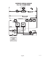
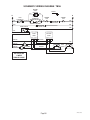
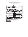
Wiring Diagrams and check the wiring harness.
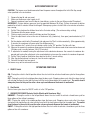
DILUTION TIMER
TIC
MA
-O- 5
NN 335 4
BU P/N
5
6
7
3
6
5
7
8
2
6
4
3
S
UTE
MIN
LAY
DE
1
S
UTE
MIN
ON
UTI
DIL
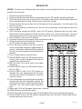
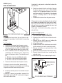
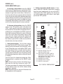
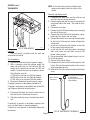
FIG. 10 DILUTION TIMER
P3040
Location:
The dilution timer is located inside the hood on the
right side. It consists of the dial plate with two dials
and circuit board.
Test Procedure:
1. Disconnect the brewer from the power source and
remove the wires from terminals TL3, TL4, & TL5
of the timer and rotate both dials fully counterclockwise.
2. With a voltmeter, check the voltage across terminals TL1 and TL2 when the ON/OFF switch is in the
"ON" position. Connect the brewer to the power
source. The indication must be:
a) 120 volts ac for two wire 120 volt models.
b) 230 volts ac for two wire 230 volt models.
c) 100 volts ac for two wire 100 volt models.
3. Disconnect the brewer from the power source.
5. With a voltmeter, check the voltage across terminals TL1 and TL4 when the ON/OFF switch is in the
"ON" position and the start switch is momentarily
placed in the lower position. Connect the brewer to
the power source. After a delay of approximately
three minutes, the indication must be:
a) 120 volts ac for two wire 120 volt models for
approximately one minute and then return to its
previous indication.
b) 230 volts ac for two wire 230 volt models for
approximately one minute and then return to its
previous indication.
c) 100 volts ac for two wire 100 volt models for
approximately one minute and then return to its
previous indication.
6. Disconnect the brewer from the power source.
If voltage is present as described, the timer is operating properly. Adjust the timer dials as required.
If voltage is not present as described, replace the
timer.
Removal and Replacement:
1. Remove all wires from the timer.
2. Remove the circuit board and dial plate from the
brackets.
4. Install the new dial plate and circuit board to the
brackets.
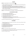
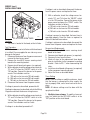
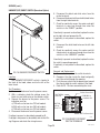
5. Refer to Fig. 11 when reconnecting the wires.
6. Adjust the timer dials as required.
If voltage is present as described, proceed to #4.
If voltage is not present as described, refer to the Wiring Diagrams and check the wiring harness.
4. Check for continuity across the green and red/
black wires when the start switch is held in the
lower position.
Page 21
WHI/BLU to Dilution Solenoid
GRN to Start Switch
RED/BLK to Start Switch
WHI to Brew Timer (100V &
120V Models)
RED to Brew Timer (230V
Models)
WHI/VIO to ON/OFF Switch
FIG. 11 DILUTION TIMER TERMINALS
P1281
37235 080204