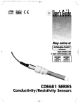
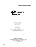
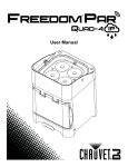
1
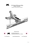
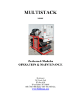
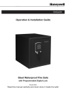
QTJ01N 1,000 LB. CAPACITY TELESCOPIC TRANSMISSION JACK Address: 200 Cabel St. Louisville, KY 40206. Sales and Service: 1-877-771-5438. Fax: 502-583-5488. Website: www.qualitylifts.com SPECIFICATIONS Capacity. . . . . . . . . . . . . . . . . . . . . . . . . . . . . . . . . . . 1,000 lb. (0.5 ton) Lowered Height . . . . . . . . . . . . . . . . . . . . . . . . . . . . . . . . . . . . . 34.25" Raised Height. . . . . . . . . . . . . . . . . . . . . . . . . . . . . . . . . . . . . . 70.866" Saddle Tilt Forward. . . . . . . . . . . . . . . . . . . . . . . . . . . . . . . . . . . . . . 15º Saddle Tilt Backward . . . . . . . . . . . . . . . . . . . . . . . . . . . . . . . . . . 7-7.3º Saddle Side to Side . . . . . . . . . . . . . . . . . . . . . . . . . . . . . . . . . . 1.575" Weight . . . . . . . . . . . . . . . . . . . . . . . . . . . . . . . . . . . . . . . . . . . . 229 lb. • DO NOT MODIFY THIS EQUIPMENT OR REMOVE LOAD RESTRAINT CHAIN. • No Alterations to the Jack Shall be Made. • ALWAYS USE THE LOAD RESTRAINT CHAIN, CORNER SUPPORT BRACKET, AND ATTACHMENTS TO STABILIZE AND FIRMLY SECURE THE LOAD TO THE SADDLE. INSURE LOAD RESTRAINT CHAIN IS TIGHT AND PROPERLY POSITIONED TO EFFECTIVELY HARNESS THE LOAD. NEVER USE THIS JACK WITHOUT A LOAD RESTRAINT CHAIN STRONG ENOUGH TO SUPPORT THE TRANSMISSION. Features • • • • • • • Two stage telescopic design provides extra range Foot activated hydraulic system Fully adjustable universal saddle Load restraint chain provided Pull handle for easy transporting of load Swivel casters for ease of mobility Wide base for stability FOR YOUR SAFETY & TO PREVENT INJURY • • THIS JACK IS NOT A LOAD SUSTAINING DEVICE. DO NOT OVERLOAD. OVERLOAD CAN CAUSE DAMAGE, FAILURE OF THE JACK AND/OR PERSONAL OR FATAL INJURY. USE ONLY ON HARD LEVEL SURFACES CAPABLE OF SUSTAINING THE LOAD. READ, STUDY AND UNDERSTAND ALL WARNING LABELS AND OPERATING INSTRUCTIONS FURNISHED WITH THIS EQUIPMENT PRIOR TO USE. IF ANY PORTION OF THIS MATERIAL IS UNCLEAR, CONTACT YOUR REPRESENTATIVE FOR CLARIF ICATION. • USE ON OTHER THAN A HARD LEVEL SURFACE WILL RESULT IN JACK INSTABILITY AND LOSS OF LOAD. • NEVER ALLOW UNSKILLED OR IMPROPERLY TRAINED PERSONNEL TO OPERATE THIS EQUIPMENT. • PRIOR TO TRANSPORTING THE LOAD, INSURE THE JACK IS IN THE LOWERED POSITION , AND THE LOAD IS CENTRALLY LOCATED ON THE SADDLE. • USE OF THE TRANSMISSION JACK IS LIMITED TO THE REMOVAL AND INSTALLATION OF TRANSMISSIONS AND TRANSFER CASES. • • DO NOT LIFT OR SUPPORT VEHICLES WITH TRANSMISSION JACK. • BE SURE VEHICLE IS APPROPRIATELY SUPPORTED BEFORE STARTING REPAIRS. QTJ01N - Operations Manual and Parts Breakdown 1 IT IS YOUR RESPONSIBILITY TO KEEP ALL WARNING LABELS AND INSTRUCTION LITERATURE LEGIBLE AND INTACT. REPLACEMENT LABELS AND LITERATURE ARE AVAILABLE FROM THE FACTORY. FAILURE TO HEED THESE WARNINGS MAY RESULT IN EQUIPMENT AND/OR PROPERTY DAMAGE AND/OR PERSONAL OR FATAL INJURY. rev. 05/14/08 QTJ01N 1,000 LB. CAPACITY TELESCOPIC TRANSMISSION JACK Item No. Part No. 1 † 2 † 3 † 4 RSJ04 5 † 6 † 7 † 8 †† 9 10 * 11 12 13 RSJ13 14 RSJ14 15 * 16 RSJ16 17 18 19 Description Qty. Nut M8 Bolt with hook Pin Adjustable platform Eye bolt M10 Chain lock Chain Nut M30 Cylinder assembly Bolt M8 x 25 Retaining Ring 9 Washer 14 Base support Caster wheel assembly Nut M8 Pedal Inner hex bolt M10 x 40 Spring washer 10 Pump release block 2 2 2 1 2 2 2 1 1 16 2 4 2 4 16 1 4 6 1 Item No. Part No. Description Qty. 19A RSJ19A Release assembly 20 "O" ring 8.5 x 1.8 21 Connecting plate 22 * Cotter pin 3 x 25 23 * Short shaft 24 * Spring washer 12 25 * Inner hex bolt M12 x 25 27 * Spring washer 8 32 RSJ32 Handle 33 Bolt M8 x 12 34 RSJ34 Crooked tube 35 † Nut M10 36 † Washer 10 37 RSJ37 Holder 38 †† Bolt M12 x 30 39 †† Bolt M12 x 25 40 †† Washer 12 41 †† Nut M12 42 Retaining ring 12 † Available in 2-Piece Chain Kit RSJCK (including #1,2,3,5,6,7,35,36). †† Available in Saddle Hardware Kit RSJSHK(including #8,38,39,40,41). * Available in Leg and Caster Hardware Kit RSJLCHK (including #10,15,22,23,24,25, 27). Note: replacement power unit available as RSJPU. QTJ01N - Operations Manual and Parts Breakdown 2 5 2 2 2 8 8 16 1 2 1 8 8 2 2 4 2 2 2 rev. 05/14/08 POWER UNIT ASSEMBLY Item No. Part No. 1 2 * 3 * 4 5 * 6 * 7 8 * 9 10 11 12 13 * 14 * 15 * 16 17 * 18 * 19 * 20 21 22 Description Qty. Cylinder bottom Filter net Cylinder bottom seal Reservoir Cylinder top seal Filler plug Cylinder Packing Retaining ring Ram head Ram Ram head Seal "O" ring "O" ring Top nut "O" ring "O" ring "O" ring Ram Bush Retaining ring 1 1 1 1 1 1 1 1 1 1 1 1 1 1 1 1 1 2 1 1 1 1 Items marked with an asterisk are available in RSJPUSK seal kit (also includes 5 pieces #20 on page 2) QTJ01N - Operations Manual and Parts Breakdown 3 rev. 05/14/08 ASSEMBLY INSTRUCTIONS 1. Install base supports (#13) to cylinder (#9) assembly by using bolts (#25) and washers (#24). Do not tighten. 2. Secure the caster wheel assemblies (#14) to the base supports (#13) using the bolts (#10), spring washers (#27) and nuts provided (15). 3. Place the complete assembly on a level floor so all caster wheel assemblies (#14) are touching the floor and tighten the bolts (#25) that secure the base supports (#13) to the cylinder assembly (#9). 4. Secure the adjustable platform (#4) to the secondary ram at the top of the cylinder (#9) assembly with the nut (#8). 5. Install the holders (#37), chains (#7), and all the related hardware to the adjustable platform (#4) as shown in the exploded view parts drawing. NOTE: do not use any kind of air ratchet or air gun to tighten any bolt on the jack. 5. Very slowly and cautiously raise the jack's saddle so the saddle brackets make contact with the transmission pan's flange. Be careful not to lift the vehicle. Activation of the jack saddle's fore and aft tilt knob and side to side knob is sometimes necessary to properly align the transmission pan's flange with the saddle brackets. Slight movement or repositioning of the jack may also be necessary for proper alignment. LOWERING: 7. Visual inspection should be made before each use of the transmission jack, checking for leaking hydraulic fluid and damaged, loose or missing parts. Each jack must be inspected by a manufacturer’s repair facility immediately, if accidentally subjected to an abnormal load or shock. Any jack which appears to be damaged in any way, is found to be badly worn, or operates abnormally MUST BE REMOVED FROM SERVICE until necessary repairs are made by a manufacturer’s authorized repair facility. It is recommended that an annual inspection of the jack be made by a manufacturer’s authorized repair facility and that any defective parts, decals or warning labels be replaced with manufacturer’s specified parts. Lower the transmission down and away from the engine according to the instructions in the vehicle repair service manual making sure the transmission will not get hung up on any electrical lines, fluid lines or any other under car components. Lower the transmission by carefully and slowly depressing the jack's release foot pedal. Maintenance Instructions: 1. 2. 3. 4. 5. A list of authorized repair facilities is on a separate page insert. Important! Before Use . . . Sometimes during shipment and handling air gets into the hydraulic system, causing poor lifting performance. Bleeding the pump: with the release pedal depressed, activate the pump pedal about 15 times to force excess air from the pump piston area. Bleeding the ram: Pump the telescopic rams up until they are fully extended by slowly pumping the foot pedal. Loosen the knurled nut on top of the first stage ram. Air will be released as the saddle slowly comes down. When oil begins to leak out of the knurled nut, tighten the nut. If the condition seems better, repeat the steps for bleeding the pump and bleeding the ram until air is purged from the jack. Use and store the jack in a protected environment where it will not be exposed to inclement weather, corrosive vapors, abrasive dust, or any harmful elements. Lubricate all moving parts once a month except for the saddle holder and brackets on top of the jack's saddle holder. It is not necessary to regularly check the jack's fluid level. If there is an external fluid leak, the jack must be serviced and/or repaired by a qualified hydraulic repair person that is familiar with this equipment. A manufacturer's authorized repair facility is recommended. IMPORTANT: NEVER USE ALCOHOL, HYDRAULIC BREAK FLUID OR TRANSMISSION FLUID AS ALTERNATIVES FOR HYDRAULIC JACK OIL. The jack label(s) must be legible and easy to read. Contact the manufacturer for a replacement label if the jack's label is unreadable. Inspect the jack for component cracks, breaks, bends, signs of damage, or fluid leaks before each use. Do not use the jack if it has loose or missing hardware or components, or is modified or altered in any way. Take corrective action before using the jack again. Owner/User Responsibility: The owner and/or user must have an understanding of the manufacturer’s operating instructions and warnings before using the transmission jack. Warning information should be emphasized and understood. If the operator is not fluent in English the manufacturer’s instructions and warnings shall be read to and discussed with the operator in the operator’s native language by the purchaser/owner, making sure that the operator comprehends its contents. Operating Instructions: Using the above-ground or in-ground hoist, raise the vehicle to the desired work height and support the vehicle with the hoist manufacturer's recommended support methods and according to the warnings given in the manual. 2. Support the vehicle's engine with an under hoist stand rated greater than the weight of the engine before unbolting the transmission. Owner and/or user must study and maintain for future reference the manufacturer’s instructions and pertinent warning information. Owner and/or user is responsible for keeping all warning labels and instruction manuals legible and intact. Replacement labels and literature are available from the manufacturer. LIFTING: 3. will configure to the transmission pan's flange. Once properly configured, tighten all holders and brackets. 6. Use jack's chain and related anchorage hardware to secure the transmission to the jack's saddle. Inspection: 1. Maneuver the transmission jack directly under the transmission. Activate the jack's pump foot pedal to raise the jack's saddle to a height very close to the center of balance point of the transmission oil pan, but do not make contact with the pan. 4. Adjust the jack's saddle holder and related contact brackets so they QTJ01N - Operations Manual and Parts Breakdown 4 rev. 05/14/08 LIMITED WARRANTY: Quality Lifts WARRANTS TO ITS CUSTOMERS THAT THE COMPANY’S HYDRAULIC JACKS ARE FREE FROM DEFECTS IN WORKMANSHIP AND MATERIALS. Quality Lifts will repair or replace its hydraulic jacks which fail to give satisfactory service due to defective workmanship or materials, based upon the terms and conditions of the following described warranty plans attributed to that specific product. This product carries a ONE-YEAR limited warranty. During this warranty period, Quality Lifts will repair or replace at our option any part or unit which proves to be defective in material or workmanship. This warranty does not cover damage and normal wear and tear to consumable parts. This warranty does not cover any repairs or replacement made by anyone other than Quality Lifts or its authorized hydraulic service centers. The foregoing obligation is Quality Lifts sole liability under this or any implied warranty and under no circumstances shall we be liable for any incidental or consequential damages. Note: Some states do not allow the exclusion or limitation of incidental or consequential damages, so the above limitation or exclusion may not apply to you. To determine if your product issue is covered by warranty, please call Quality Lifts sales and service number. If a repair or replacement part is needed, a RMA # will be issued. Return equipment or parts to any Quality Lifts authorized service center, transportation prepaid. Be certain to include your name and address, evidence of the purchase date, Quality Lifts RMA# and description of the suspected defect. If you have any questions about warranty service, please write to Quality Lifts. This warranty gives you specific legal rights and you may also have other rights which vary from state to state. Repair kits and replacement parts are available for purchase from authorized hydraulic service centers if product is no longer covered by a warranty plan. Address: 200 Cabel St. Louisville, KY 40206. Sales and Service: 1-877-771-5438. Fax: 502-583-5488. Website: www.qualitylifts.com QTJ01N - Operations Manual and Parts Breakdown 5 rev. 05/14/08