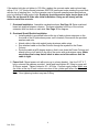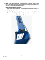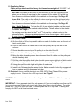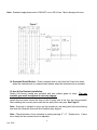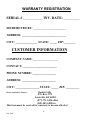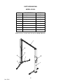
1
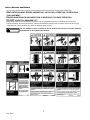
RAISING THE LEVEL OF PERFORMANCE
MODEL Q10000
TWO POST
10,000 lbs Capacity
2,500 lbs per Arm
INSTALLATION, OPERATION MANUAL
AND PARTS BREAKDOWN
QUALITY LIFTS L.P.
200 Cabel St., P.O. Box 3972, Louisville, KY 40201
PHONE: 502-583-5438 FAX: 502-583-5488
TOLL FREE: 877-771-5438
www.qualitylifts.com
1
Jan. 2006
SAFETY NOTICES AND DECALS
For your safety, and the safety of others, read and understand all of the safety notices and decals included here.
READ ENTIRE MANUAL BEFORE ASSEMBLING, INSTALLING, OPERATING, OR SERVICING
THIS EQUIPMENT.
PROPER MAINTENANCE AND INSPECTION IS NECESSARY FOR SAFE OPERATION.
DO NOT OPERATE A DAMAGED LIFT.
Safety decals similar to those shown here are found on a properly installed lift. Be sure that all safety decals have been
correctly installed on the Power Unit reservoir. Verify that all authorized operators know the location of these decals and fully
understand their meaning. Replace worn, faded, or damaged decals promptly.
WARNING
Do not attempt to raise a vehicle on the lift until the lift has been correctly installed
and adjusted as described in this manual.
2
Jan. 2006
1. Lift Location: Use architects plan when available to locate lift in shop. See Figure 1
for a typical bay layout.
Figure 1
Typical Bay Layout
6' TO NEAREST
OBSTRUCTION
OR 7' TO
NEAREST WALL
144" [12'-0"]
MIN.TO
NEAREST
OBSTRUCTION
COLUMN BASE PLATES
135 1/2"
144" [12'-0"]
MIN. TO
NEAREST
OBSTRUCTION
NOTE: Power Column is recommended to be installed on the passenger side of lift. See Page
13 for Power and Idler Column diagram.
3
Jan. 2006
2. Lift Height: See Figure 2 for overall height of lift. Allow a minimum of 1” between
lowest obstruction and top of lift.
Figure 2
12'-4"
Cylinder
Height
113"
Inside of
Colum ns
12'-3 1/2"
or
11'-5 1/2"
Adjustable
Overhead
Height
12'-1/2"
or
11'-2 1/2"
Adjustable
Colum n
Height
78 1/2"
Rise Height
11'-9"
or
10'-11 3/4"
Floor to
Overhead
Shut-off Cable
(Screw Pad Highest Position)
5" to 9"
Screw Pad
Height
135 3/4"
Over All W idth
3. Lock Release Pulley: Install the lock release pulley to the column extensions. You will
find the pulleys attached to inside of column extension or in the parts box. The pulley
must be installed with the pulley up and the bracket mounted to the outside of the
column extension. See Figure 3.
Top pulley should line up with pre-attached pulley near the locking pawl on column.
4. Column Extensions: Install column extensions before standing columns.
See Page 15.
Figure 3
The Lock Release Pulley is
located inside extension for
shipping
4
Jan. 2006
5. Lift Setting: Position columns in bay using dimensions shown in Figure 1. Again, It is
recommended that the column with power unit mounting bracket be located on
passenger side of lift. Both column base plates must be square to one another.
Concrete and Anchoring: Concrete shall have a compression strength of 3,000 PSI and a
minimum thickness of 4” in order to achieve a minimum anchor depth of 3 ¼”. This applies
when using the standard supplied ¾” X 5 ½” anchors. If the top of the anchor exceeds 2 ¼”
above the floor grade you DO NOT HAVE ENOUGH ANCHOR DEPTH.
Drill 10 – ¾” diameter holes in the concrete floor using the holes in the column base plate as a
guide. See Figure 4 for hole depth, hole spacing and edge distance requirements.
Figure 4
Concrete Thickness and Hole Depth
4.00 inches
Edge distance from cracks and seams 4.75 inches
Hole spacing
6.50 inches
Caution: DO NOT INSTALL this lift on asphalt or other similar unstable surfaces. The
columns for this lift are supported only by the anchor bolts.
6. IMPORTANT: Using the horseshoe shims provided, shim each column base until each
column is plumb. If one column has to be elevated to match the plane of the other
column, full size base shim plates should be used. Recheck columns for plumb.
Tighten anchor bolts to an installation torque of 150 ft.-lbs. Shim thickness MUST NOT
exceed ½” when using the 5 ½” long anchors provided with lift. Plumb the column
uprights. See Figure 5.
Figure 5
NOTE: If more than 2 horseshoe shims are used at any of the column anchor bolts, pack nonshrink grout under the unsupported area of the column base. Insure shims are held tightly
between the base plate and the floor after torquing the anchor bolts.
5
Jan. 2006
If the anchor bolts do not tighten to 150 ft-lbs, replace the concrete under each column base
with a 4’ X 4 ‘ X 6” thick concrete (minimum 3000 PSI) pad keyed under existing floor and flush
with the top of existing floor. Let the concrete cure to concrete manufacturers specifications
prior to installing lift and anchor bolts. Routinely check the anchor bolts- torque them to 90
ft-lbs. Do not exceed 90 ft-lbs after initial installation. Doing so will slowly pull the
anchors out of the concrete.
7. Overhead Installation: Assemble overhead sections. See Page 18. Raise overhead
beam into position between columns. The beam attaches to the top of the column
extension with four bolts on each side. See Page 15 for diagram.
8. Overhead Shutoff Switch Installation:
• Install eyebolts in pre-drilled holes at the top of each column extension on the
front side of the lift (side where power unit is located). Secure with the provided
washers and nuts.
• Attach cable to Idler side eyebolt using aluminum cable crimp.
• Run attached cable on the Idler Column through the eyebolt on the Power
Column.
• Route the cable at a 90 degree angle so that it runs down the Power Column and
attach to the cut-off switch in the top of the motor with an aluminum crimp. Make
sure before final crimp that all slack is taken out of the cable so that the
cable is tight.
9. Power Unit: Mount power unit with motor up to column bracket. Use four 5/16” X 1”
bolts, nuts and flat washers provided. Install and hand tighten 90° fitting to pump until
O-Ring is seated. Tighten locknut to 35 – 40 ft-lbs. Connect supply hoses. Make sure
the hoses at the top of each column are clear of the cylinder path when the lift is at full
rise.
Note: Over tightening locknut may tear O-Ring.
6
Jan. 2006
10. Hoses: Clean adapters and hoses. Inspect all threads for damage. Inspect all hose
ends to be sure they are crimped. Route hose over Column Extension making sure to
stay clear of cylinder at full stroke, see Figure 6
Flared Fittings Tightening Procedure:
1. Screw fittings together finger tight. Using proper size wrench, rotate the fitting 2 ½”
hex flats.
2. Back the fitting off one full turn.
3. Again tighten the fittings finger tight. Using a wrench, rotate the fitting 2 ½” hex flats.
This will complete the tightening procedure and develop a pressure tight seal.
Figure 6 - Hose Routing
7
Jan. 2006
11. Equalizing Cables:
Cables are pre attached at the factory for the maximum height of 12’-3 1/2”. Pull
cables from column.
Idler Side: The cable on the offside of column must go over the right hand pulley
(when you are facing the carriage) on the overhead on both sides of lift at the top.
Then down the column and attach to the cable tab on the carriage. See Page 20
Power Side: The cable on the offside of column must go over the right hand pulley
(when you are facing the carriage) on the overhead on both sides of lift at the top.
Then down the column and attach to the cable tab on the carriage. See Page 20
Note - Height Reduction: To lower the lift, the pre attached cables must be moved
up, inside the carriage to the optional cable brackets. This will adjust for the slack in
the cables. See Page 20
The carriage must be raised to the 1st or 2nd lock position to attach cables to the
optional brackets. Use appropriate equipment to raise the carriages to latch position.
Be sure locking latch is securely engaged.
12. Lock Release Cable:
A. On the offside of lift slip loop end of cable over end of shoulder screw on the side of
latch control plate.
B. Feed to other end of the cable down to the latch pulley then up the side of the
column
C. Route the cable over the top of the pulley to the far side of the lift.
D. Route the cable of the top pulley on the power side of the lift.
E. Bring the cable down the power side column and feed the cable over the pulley just
above the safety latch.
F. Pull the cable through the hole in the shoulder screw on the right side of latch control
plate. You may have to loosen the setscrew before pulling cable through.
G. Using pliers pull the cable tight and tighten the setscrew.
H. Install Latch Release Handle and test locks. Make sure both locks fully engage lock
bar on carriage and fully disengage lock bar.
13. Electrical: Have a certified electrician run 208 – 230V Single Phase 60 Hz power
supply to motor. Size wire for a 25 Amp circuit. See Figure 7
CAUTION: Never operate the motor on line voltage less than 208 Volts. Motor damage may
occur.
IMPORTANT: Use a separate circuit for each power unit if you are installing more than one lift
in your service area. Protect each circuit with a time delay fuse or circuit breaker. For single
phase 208 – 230V use a 25 Amp fuse. For three phase use a 15 amp fuse. All wiring must
comply with NEC and all local electrical codes.
8
Jan. 2006
Note: Standard single-phase motor CAN NOT run on 50 Hz line. Motor damage will occur.
Figure 7
14. Overhead Shutoff Switch: Check overhead wire to verify that the Power Unit stops
when the overhead wire is contacted and restarts when the overhead wire is released.
15. Arm & Arm Restraint Installation:
Quality Lifts factory installs arm restraints and arm restraint gears on arms. The arm
restraint gear must be adjusted to correctly engage.
Install the short arms toward the front of the lift using one of the four arm pins provided.
After installing the four arm pins install the four split pins in arm pins. See Page 13.
Note: Once arm is installed in yoke, pull up actuator pin and swing arm fully around being
sure that Arm Restraint Gear and Arm Restraint stay aligned.
Note: Check operation of arm restraints by raising carriage 3” – 6”. Rotate arms. If arms
move freely the arm restraint must be adjusted.
9
Jan. 2006
After installing and adjusting arm restraints it is necessary to grease with white lithium
grease.
16. Oil Fill and Bleeding: Use Dexron III ATF or Hydraulic Oil (must be anti-foam, antirust) that meets ISO 32 specifications to fill the reservoir on the power unit. Remove fillbreather cap and pour in fluid until full. Raise lift up just under the 1st locking position
(do not place on lock). Loosen the 6mm bleed screws located at the top of cylinders on
the sides. Start power unit and run up until the oil seeps out of the bleed screws. When
this occurs, the cylinders have been properly bled of air. Tighten the bleed screws and
Replace fill-breather cap on the power unit.
If fill–breather cap is lost or broken order a replacement. Reservoir must be vented.
17. Lock Release Cable Adjustment:
A. Check to make sure the latch will properly engage and disengage. Slowly release the
latch handle. At 1/8” gap between the top of the latch dog and the column is allowable.
B. When raising lift, listen to latches to be sure that both latch dogs fall into the latch slots
almost simultaneously. If they do not, loosen the setscrew for the latch cable and adjust
tension as necessary.
C. Install both latch covers.
18. Pressure Test: Run lift to full rise and keep motor running for 5 seconds. Stop and
check all hose connections. Tighten or reseal and leaks discovered.
19. Equalizer Cable Adjustment: Raise the lift to check equalizer cable tension. Below
the carriage, grasp the two adjacent cables between your thumb and forefinger and pull
them together. This should require approximately 15 lbs. of pressure.
20. Lubricate Bearing Surface: Quality Lifts are shipped without any lubrication of the
bearing surfaces. After installation is complete and before operating the lift all 4 bearing
surfaces in each column need to be lubricated. Using the supplied tub of grease, apply
to all 4 corners of the column (on the inside) above and below the carriage. (Any type of
shop grease can be used to lubricate the columns, if the supplied tub is not available).
Upon the raising and lowering of the lift, grease will be worked in sufficiently. This is a
regular maintenance procedure that should be done routinely to ensure the full life of
the lift.
21. Serial Number and Decal: The serial number is written on the outside of the power
unit box. It will be an eight digit number starting with four 0’s (ie. 00002995) and the
decal should be attached to the power side column for easy recognition. If the serial
tag is not on the column, it will be located in the power unit box with the elbow fitting
for the hydraulic line. When talking to the factory (Quality Lifts), always be prepared
to identify the lift by this serial number. This is how we track ALL lifts
Place the Quality Lifts decal on one of the column extensions. Simply take
backing off and apply to the column (making sure it is straight) and rub the
letters off.
10
Jan. 2006
WARRANTY REGISTRATION
SERIAL # ___________ INV. DATE: _________
DISTRIBUTED BY: ________________________________
ADDRESS: ______________________________
CITY: _______________ STATE: _____ ZIP:________
CUSTOMER INFORMATION
COMPANY NAME: ________________________
CONTACT: _______________________
PHONE NUMBER: ________________
ADDRESS: _______________________
CITY: ________________ STATE: _____ ZIP: _________
Quality Lifts
P.O. Box 3972
Louisville, KY 40201
(877) 771-5438 office
(502) 583-5488 fax
This form must be received for warranty to become effective!
Please remit above form to:
11
Jan. 2006
PARTS BREAKDOWN
MODEL Q10000
ITEM #
DESCRIPTION
PAGE #
1
Power Column
15
2
Idler Column
15
3
Carriage
16
4
Overhead
18
5
Cylinder
17
6
Long Arm
17
7
Short Arm
17
8
Power Unit
15
Replace all worn or broken parts with genuine Quality Lifts parts.
4
12
Jan. 2006
MODEL Q10000
COLUMN AND LOCK
ITEM #
PART #
QTY
DESCRIPTION
9
26C02010
2
Column
10
26K80110
2
Column Extension
11
26K06185/95
2
Lock Release Cover
12
26K06100
2
Lock Release Shaft
13
26K06140
2
Lock Release Spring 1
14
PHANDLE30M10
2
Lock Release Handle
15
26K70140
2
Lock Release Shaft
16
26K06090
2
Lock Release Wire Pin
17
26K06130
2
Lock Release Spring 2
18
SN-E19
4
E-Snap Ring
19
26K06080
2
Lock Release Connector
20
WBM0615
2
Connector Bolt
21
26K06210
2
Lock Spacer
22
26K06110
2
Lock Pawl
23
SPIN0640
2
Spring Pin
24
26K06120
4
Lock Release Pulley
25
26K02150
2(R/1L)
Lock Release Bracket
26
26K06160
2
Pulley
27
AB-1534
1
Power Unit
28
HNM10
8
Hex Nut
29
WPM10
8
Flat Washer
30
HEXM1025
8
Hex Bolt
31
26C76100
1
Overhead
32
SN-E08
4
E-Snap Ring
33
SN-E15
2
E-Snap Ring
34
TRTBM0608
4
Pan Head Screw
35
WBM1020
20
Socket Head Bolt
Replace all worn or broken parts with genuine Quality Lifts parts.
13
Jan. 2006
MODEL Q10000
COLUMN AND LOCK
14
Jan. 2006
MODEL Q10000
CARRIAGE, ARMS AND CYLINDER
ITEM #
36
37
38
39
40
41
42
43
44
45
46
47
48
49
50
51
52
53
54
55
56
57
58
59
60
61
62
63
64
65
66
67
68
69
70
71
72
73
74
75
76
77
78
79
80
PART#
26K0400
26C06060/70
26K70111
26K06150
WPM08
WBM0830
26K05000
26K05000
26K05000
26K05000
26C06018
26K05000
26K05000
26K05000
26K05000
26K05000
26K05000
26K05000
26K05000
26K05000
26K05000
WBM1230
WSM12
WPM12
26C25040
WPM10
WSM10
HEXM1030
26C23100
26C21100
26K32000
26K34000
26K36000
WBM0615
26K25030
26K25010
SN-CS25
26K25020
SN-CS45
26C06040
SPIN0640
SPIN0650
26K06050
26K06030
WBM1015
QTY
2
8/8
4
2
4
4
2
2
2
2
2
2
2
8
8
2
2
2
2
2
2
2
2
2
4
12
12
12
2
2
2
2
2
4
4
4
4
4
8
4
8
4
4
4
6
DESCRIPTION
Carriage
Carriage Slide Blocks
Arm Shaft
Rubber Door Protector
Flat Washer
Allen Bolt
Piston Rod
Wear Ring
Piston
Locking Bolt
Hose Adapter Assembly
Cylinder
Gland
Steal Ball
Locking Bolt
Dust Seal
U-Packing
Back Up Ring
O-Ring
Back Up Ring
Bearing
Allen Bolt
Spring Washer
Flat Washer
Large Arm Restraint Gear
Flat Washer
Spring Washer
Hex Bolt
Long Slide Arm
Long Arm
Short Arm
Short Slide Arm
Short Slide Arm 2
Wrench Bolt
Arm Support Rubber Footpad
Arm Support
Snap Ring- Small
Arm Supporter 2nd Screw
Snap Ring- Large
Small Arm Restraint Gear
Spring Pin
Spring Pin
Arm Restraint Spring
Small Gear Shaft
Allen Bolt
Replace all worn or broken parts with genuine Quality Lifts parts.
15
Jan. 2006
MODEL Q10000
CARRIAGE, ARMS AND CYLINDER
16
Jan. 2006
MODEL Q10000
OVERHEAD
ITEM #
PART #
QTY
DESCRIPTION
81
26K76300
1
Overhead (1)
82
26K76300
1
Overhead (2)
83
26K40010
2
Pulley Shaft
84
SN-CS20
4
Snap Ring
85
26K06160
4
Pulley
86
26K40510
2
Pulley Spacer
87
HNM10
10
Hex Nut
88
WPM10
10
Flat Washer
89
HEXM1025
10
Hex Bolt
90
WSM10
10
Spring Washer
Replace all worn or broken parts with genuine Quality Lifts parts.
17
Jan. 2006
MODEL Q10000
HYDRAULICS
ITEM #
PART #
QTY
DESCRIPTION
91
26K70120
1
Pressure Hose 1- 5/16”x1W
92
26C00010
1
Pressure Hose 2- 5/16”x1W
93
26K01030
1
Pressure Hose 3- 5/16”x1W
94
26K01040
1
Union Tee
95
HMCM-1/4-O5U
1
Oil Steel Nipple
96
26K06020
1
Hose Adapter Block
97
38100400
1
Oil Nipple
98
31S71203
1
Orifice Spring
99
26K06180
1
Orifice
Replace all worn or broken parts with genuine Quality Lifts parts.
18
Jan. 2006
MODEL Q10000
SYNCHRONIZATION
ITEM #
PART#
QTY
DESCRIPTION
100
26K06160
6
Pulley
101
26K06010
2
Cable
102
26K06011
2
Cable Bolt
103
26K06012
2
Cable Bolt
104
HNM12
8
Hex Nut
105
WPM12
4
Flat Washer
Replace all worn or broken parts with genuine Quality Lifts parts.
19
Jan. 2006
MODEL Q10000
OPERATION AND MAINTENANCE PROCEDURE
SAVE THESE INSTRUCTIONS deliver them to owner/user/employee along with other
materials furnished with this lift.
Demonstrate the operation of the lift to the owner/operator and review correct and safe lifting
procedures using the Lifting It Right booklet as a guide.
Complete the warranty registration form (page 11) and fax back, or mail to Quality Lifts. Failure
to do this could void the warranty
OPERATION PROCEDURE
SAFETY NOTICES AND DECALS
This product is furnished with graphic safety warning labels, which are reproduced on page 2 of
these instructions. Do not remove or deface these warning labels, or allow them to be removed
or defaced. For your safety, and the safety of others, read and understand all of the safety
notices and decals included.
OWNER/EMPLOYER RESPONSIBILITIES
This lift has been designed and constructed according to ANSI/ALI ALCTV-1998 standard. The standard applies
to lift manufactures, as well as to owners and employers. The owner/employer’s responsibilities as prescribed by
ANSI/ALI ALOIM-2000, are summarized below. For exact wording refer to the actual standard provided with
this manual in the literature pack.
The Owner/Employer shall insure that lift operators are qualified and that they are trained in the safe
use and operation of the lift using the manufacturer’s operating instructions; ALI/SM 93 -1, ALI Lifting it
Right safety manual; ALI/ST-90 ALI Safety Tips card; ANSI/ALI ALOIM-2000, American National
Standard for Automotive Lifts-Safety Requirements for Operation, Inspection and Maintenance; ALI/WL
Series, ALI Uniform Warning Label Decals/Placards; and in case of frame engaging lifts, ALI/LPGUIDE, Vehicle Lifting Points/Quick Reference Guide for Frame Engaging Lifts.
The Owner/Employer shall establish procedures to periodically inspect the lift in accordance with the
lift manufacturer’s instructions or ANSI/ALI ALOIM-2000, American National Standard for Automotive
Lifts-Safety Requirements for Operation, Inspection and Maintenance; and the employer shall insure
that the lift inspectors are qualified and that they are adequately trained in the inspection of the lift.
The Owner/Employer shall establish procedures to periodically maintain the lift in accordance with the
lift manufacturer’s instructions or ANSI/ALIOIM-2000, American National Standard for Automotive LiftsSafety Requirements for Operation, Inspection and Maintenance; and the employer shall insure that the
lift maintenance personnel are qualified and that they are adequately trained in the maintenance of the
lift.
The Owner/Employer shall maintain the periodic inspection and maintenance records recommended
by the manufacturer or ANSI/ALI ALOIM-2000, American National Standard for Automotive Lifts-Safety
Requirements for Operation, Inspection and Maintenance.
The Owner/Employer shall display the lift manufacturer’s operating instructions; ALI/SM 93 -1, ALI
Lifting it Right safety manual; ALI/ST-90 ALI Safety Tips card; ANSI/ALI ALOIM-2000, American
National Standard for Automotive Lifts-Safety Requirements for Operation, Inspection and
Maintenance; and in the case of frame engaging lift, ALI/LP-GUIDE, Vehicle Lifting Points/Quick
Reference Guide for Frame Engaging Lifts; in a conspicuous location in the lift area convenient to the
operator.
20
Jan. 2006
Important Safety Instructions
When using your garage equipment, basic safety precautions should always be followed,
including the following:
1
Read all instructions.
2
Care must be taken as burns can occur from touching hot parts.
3
4
To reduce the risk of fire, do not operate equipment in the vicinity of open
containers of flammable liquids (gasoline).
Adequate ventilation should be provided when working on operating internal
combustion engines.
5
Keep hair, loose clothing, fingers, and all parts of body away from moving parts.
6
To reduce the risk of electric shock, do not use on wet surfaces or expose to rain.
7
Use only as described in this manual. Use only manufacturer’s recommended
attachments.
Save These Instructions
21
Jan. 2006
PREPARATION
1) When operating the lift up or down, keep your concentration on the
vehicle and what you are doing.
2) If there are two or more lifts, make sure not to touch the controls of
another lift.
3) Do not lift a vehicle that exceeds the maximum capacity of this lift.
4) Do not lift a vehicle with a person or load inside.
5) When raising or lowering the lift, make sure to pause 1-2 seconds
between the transitions.
6) This lift is designed for automotive maintenance only. Do not use the lift
for any other purpose. Doing so could void the warranty.
7) If any of the safety devices are not operating correctly, stop the lift
immediately and locate the problem. DO NOT OVERIDE ANY OF
SAFETY FEATURES, doing so could result in serious injury or even
death.
8) Any defect or damage that occurs due to mishandling or maintenance
could void the warranty.
9) Make sure to drive the vehicle smoothly into and away from the lift and
avoid sudden stops. The tires may be slippery, especially if wet.
10) Never go under the vehicle while operating the lift. If there is a
possibility of the vehicle falling- immediately leave the area.
11) Do not operate the lift if the vehicle is tilted or leaning. This could cause
the vehicle to fall.
12) This unit is not designed for outdoor installation or for car wash
purposes. Doing so could void the warranty.
22
Jan. 2006
LIFTING A VEHICLE
1) Insure carriages are at the lowest position and the lifting arms are open to
their full drive thru position.
2) Position the vehicle in the bay so that the vehicle’s “center of gravity” is
located between the two columns.
Insure that the highest point of the vehicle will make contact with the
overhead shut-off cable..
Do not place vehicle in the bay backwards.
Do not attempt to lift the vehicle with only two arms, doing so could void
the warranty.
Refer to vehicle manufacturers service manual, technical bulletins,
“ Vehicle Lifting Points Guide” or other publications to locate the
recommended lifting points.
3) Position the arms and adapters so all four pads contact the vehicle
simultaneously.
The vehicle should remain level during lifting and lowering.
4) Raise the lift until all four wheels are just off the ground. Test the stability
by slightly rocking the vehicle. Check pads to ensure they are in secure
contact with vehicle lifting points. If the vehicle seems unstable, lower the
lift and readjust the arms. When vehicle is in a stable position raise it just
above the desired working height.
5) Lower the vehicle until the safety latches on BOTH columns engage. At
this point the vehicle should be stationed in a level position. If only one
side engages, stop lowering the vehicle, raise it several inches, and try to
engage both latches again. The vehicle is not secure until the lift is
engaged in both latches.
Always lower the lift into the locks before going under the vehicle.
Always use recommended safety stands when removing or installing
heavy components.
23
Jan. 2006
LOWERING A VEHICLE
1) Insure that the area under and around the vehicle is clear of personnel
and tools.
2) Raise the vehicle until both locking latches are released.
3) Disengage the latches by pulling down and holding the lock release
handle. This is a single point lock release and holding the handle down
releases the locks in both columns.
4) Lower the vehicle by depressing the lowering (dump) valve handle.
5) Continue to lower the vehicle until the carriages stop against the base
plate. At this point the arm restraints will automatically disengage.
Retract the extension arms and place the arms in the drive thru position.
It is now safe to drive the vehicle out of the bay.
MAINTENANCE
To avoid personal injury permit only qualified personnel to perform
maintenance on this equipment.
The following maintenance points are suggestions for a preventive
maintenance program. The actual program should be tailored to the
particular installation.
• Never operate the lift until the proper repair is completed. Using the lift with the
defect not repaired may cause damage, serious accident or even death. Doing so
could void the warranty.
• If lift stops short of full rise or chatters going up, check the fluid
level and bleed both cylinders as explained in installation
instructions.
• Only use parts or accessories that are authorized by Quality Lifts.
24
Jan. 2006
DAILY
•
Keep lift components clean and dry.
•
Check for loose or broken parts.
•
Check hydraulic system for any fluid leaks.
WEEKLY
•
Check arm support rubber footpads (Item 70 Page 16) for abrasions and
deformations.
•
Check synchronization cables and pulleys for excessive wear. Replace as required
with genuine Quality Lifts parts.
•
Check synchronization cable tension as described in installation instructions.
Adjust if necessary.
MONTHLY
• Check the anchor bolts- torque them to 90 ft-lbs. Do not exceed 90
ft-lbs after initial installation. Doing so will slowly pull the anchors out of the concrete.
•
Check overhead shutoff switch. While raising lift, trigger the shutoff cable. The
power unit motor should stop when the cable is raised. This is very important to
keep from running a vehicle into the overhead beam.
•
Lubricate bearing surfaces- Use the supplied tub or any heavy viscous grease to
lubricate the 4 inside corners (bearing surfaces) of both columns. This will help
against unusual “wear and tear” on the carriage slide blocks and column surface.
SEMI-ANNUALLY
•
Check power unit hydraulic fluid level per the installation instructions.
•
Check carriage slide blocks for abrasions.
IF ANY PROBLEMS ARE ENCOUNTERED CONTACT YOUR LOCAL
SERVICE REPRESNTATIVE OR THE MANUFACTURER FOR
ASSISTANCE.
25
Jan. 2006
TROUBLE SHOOTING GUIDE
Q10000
TROUBLE
CAUSE
SOLUTION
Lift going up unlevel
1) Synchronization cables out
out of adjustment
2) Lift is installed on unlevel
floor
1) Adjust cables to the correct
tension (See manual)
2) Shim lift to level columns
(Do not exceed ½”)
Carriages not going
up
1) Leak in hydraulic system
2) Overloading the lift
rated capacity
3) Problem with pressure
relief valve
1) Find and repair leak
2) keep load under the
3) Clean or replace the
valve
Carriages not going
down
1) Carriage still engaged in
the lock
2) Lowering valve clogged
1) Raise lift up, push lift
lowering valve, and lower
2) Check lowering valve in
power unit
3) Vehicle not loaded (spotted) 3) Check pickup points for
correctly
that particular vehicle
4) Foreign object blocking
4) Remove the object
the carriage
Locking latches do
not engage
1) Lock release shaft rusted.
(Usually occurs on outside
installations or wash bays)
2) Lock release spring
broken
3) Lock release cables
need adjustment
1) Remove covers, oil the
mechanism. Operate locks
to allow oil to penetrate
2) Replace broken spring
Lift chatters on the
way up
1) Air in the cylinders
1) Bleed cylinders
Fluid Leak
1) Defect in hydraulic hose
2) Defect in fitting
1) Replace hydraulic hose
2) Tighten fitting, and replace
if necessary
3) Repack seals or replace
cylinder if necessary
3) Defect in cylinder
packing (seals)
26
Jan. 2006
3) Adjust clamp at cable end
Fluid is contaminated
1) Water or foreign substance
1) Replace hydraulic fluid
Slow lowering speed
1) Plugged cylinder orifice
2) Lowering valve (screen)
clogged
3) Wrong weight of fluid
4) Pinch or restriction in
hydraulic hoses
5) Foreign object in carriage
1) Remove and clear orifice
2) Remove and clean
valve
3) Replace with
recommended fluid
4) Clean and/or replace
hydraulic hoses
5) Remove foreign object
Footpads slipping
from pickup point
when raising lift
1) Column not plumb
1) Plumb columns
Arms dragging on
floor (sagging)
1) Lift out of plumb
2) Unlevel floor
1) Plumb columns
2) Replace floor or shim
columns
3) Replace arm pins
4) Replace parts
3) Worn arm pins
4) Worn arm or carriage
holes
5) Worn carriage slide
blocks
6) Bent arm (overloaded)
Anchors will not
stay tight
5) Replace slide blocks
6) Replace arm and check
damage to carriage
1) Oversized holes
2) Concrete floor thickness
or PSI strength not
sufficient
3) Anchors not torqued
correctly
Abnormal noise from
the power unit
1) Overloading the lift
3) Torque bolts to the
correct spec
1) Keep load under the
rated capacity.
2) Check fluid level, fill and
bleed cylinders
2) Hydraulic fluid low
27
Jan. 2006
1) Relocate lift using a new
bit to drill holes
2) Tear out old concrete and
pour new pads for the lift
Motor will not work
1) Defect in motor
2) Fuse disconnected
3) Defect in power
button
4) Overhead shut-off
cable is activated
5) Incoming power
voltage is less than
220V that is needed
1) Contact service center
2) Fix fuse
3) Replace button
4) Deactivate shut-off system
5) Have licensed electrician
check the wiring
If you do not feel comfortable or qualified with trying the “Solutions” contact an
authorized service center immediately to perform the necessary procedures.
Contact Quality Lifts if you need a recommendation for a service center.
28
Jan. 2006