1
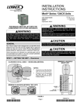
INSTALLATION INSTRUCTIONS E2013 Lennox Industries Inc. Dallas, Texas, USA Elite® Series XC14 Units AIR CONDITIONER 507018-01 6/2013 Supersedes 7/2012 RETAIN THESE INSTRUCTIONS FOR FUTURE REFERENCE Litho U.S.A. WARNING Improper installation, adjustment, alteration, service or maintenance can cause property damage, personal inju ry or loss of life. Installation and service must be performed by a licensed professional installer (or equivalent) or service agency. WARNING The State of California has determined that this product may contain or produce a chemical or chemicals, in very low doses, which may cause serious illness or death. It may also cause cancer, birth defects, or reproductive harm. NOTICE ! For more in-depth information, consult the Installa tion and Service Procedures manual, available as Corp. 0704-L2 on DaveNet or through the Technical Support department at 800-453-6669. General This XC14 outdoor air conditioner is designed for use with HFC-410A refrigerant only. This unit must be installed with an approved indoor air handler or coil. See the Lennox XC14 Product Specifications bulletin (EHB) for approved indoor component match ups. These instructions are intended as a general guide and do not supersede local codes in any way. Consult authorities having jurisdiction before installation. CAUTION As with any mechanical equipment, contact with sharp sheet metal edges can result in personal injury. Take care while handling this equipment. STEP 1 -- SETTING THE UNIT -- Clearances ÍÍÍÍÍÍÍÍÍÍÍÍÍ ÍÍÍÍÍÍÍÍÍÍÍÍÍ ÍÍÍÍÍÍÍÍÍÍÍÍÍ ÍÍÍÍÍÍÍÍÍÍÍÍÍ ÍÍÍÍÍÍÍÍÍÍÍÍÍ ÍÍÍÍÍÍÍÍÍÍÍÍÍ ÍÍÍÍÍÍÍÍÍÍÍÍÍ ÍÍÍÍÍÍÍÍÍÍÍÍÍ ÍÍÍÍÍÍÍÍÍÍÍÍÍ ÍÍÍÍÍÍÍÍÍÍÍÍÍ ÍÍÍÍÍÍÍÍÍÍÍÍÍ ÍÍÍÍÍÍÍÍÍÍÍÍÍ See NOTES See NOTES See NOTES See NOTES Control Box NOTES: Service clearance of 30 in. must be maintained on one of the sides adjacent to the control box. Clearance to one of the other three sides must be 36 in. Clearance to one of the remaining two sides may be 12 in. and the final side may be 6 in.. A clearance of 24 in. must be maintained between two units. 48 in. clearance required on top of unit. FIGURE 1 6/2013 *2P62013* Page 1 507018-01 *P507018-01* UNIT DIMENSIONS - INCHES (MM) LIQUID LINE CONNECTION C ELECTRICAL INLETS A SUCTION LINE CONNECTION 4-3/4” (121) 4-1/2” (108) B TOP VIEW SIDE VIEW XC14 Dimensions - in. (mm) Model A B C D XC14-018-230 31 (787) 27 (686) 28 (711) E XC14-024-230 31 (787) 30-1/2 (775) 35 (889) 13-7/8 (352) 7-3/4 (197) XC14-030-230 XC14-036-230 XC14-042-230 XC14-041-230 39 (991) 39 (991) 31 (787) 39 (991) 30-1/2 (775) 35 (889) 13-7/8 (352) XC14-048-230 35 (889) 30-1/2 (775) 35 (889) XC14-047-230 XC14-060-230 35 (889) 35 (889) 35-1/2 (902) 39-1/2 (1003) F G H I J 3-1/4 (83) 27-1/8 (689) 3-5/8 (92) 4-1/2 (114) 20-5/8 (524) 7-3/4 (197) 3-1/4 (83) 27-1/8 (689) 3-5/8 (92) 4-1/2 (114) 20-5/8 (524) 13-7/8 (352) 7-3/4 (197) 3-1/4 (83) 27-1/8 (689) 3-5/8 (92) 4-1/2 (114) 20-5/8 (524) 16-7/8 (429) 8-3/4 (222) 3-1/8 (79) 30-3/4 (781) 4-5/8 (117) 3-3/4 (95) 26-7/8 (683) See XC14-018 base section below. UNIT SUPPORT FEET UNIT SUPPORT FEET 8-1/2” (216) 9-1/2” (241) D 8-3/4 (222) 8-1/4” (210) E 5-1/2” (140) J I F 13-1/2” (343) G H XC14-024 TO -060 BASE WITH ELONGATED LEGS XC14-018 BASE SECTION (SMALL) Page 2 ELEVATED SLAB MOUNTING USING FEET EXTENDERS STEP 1 -- SETTING THE UNIT (Continued) -- Unit Placement 2” (50.8MM) SCH 40 FEMALE THREADED ADAPTER NOTICE ! Roof Damage! This system contains both refrigerant and oil. Some rubber roofing material may absorb oil, causing the rubber to degrade. Failure to follow this notice could result in damage to roof surface. Use additional 2” SCH 40 male threaded adapters which can be threaded into the female threaded adapters to make additional adjustments to the level of the unit. 2” (50.8MM) SCH 40 MALE THREADED ADAPTER IMPORTANT ! Exhaust vents from dryers, water heaters and furnaces should be directed away from the outdoor unit. Prolonged exposure to exhaust gases and the chemicals contained within them may cause condensation to form on the steel cabinet and other metal components of the outdoor unit. This will diminish unit performance and longevity. BASE LEG DETAIL PLACEMENT Install unit away from windows. FIGURE 4 CAUTION Before attempting to perform any service or mainte nance, turn the electrical power to unit OFF at discon nect switch. STABILIZING UNIT ON UNEVEN SURFACES #10 X 1/2” LONG SELF-DRILLING SHEET METAL SCREWS TWO 90° ELBOWS INSTALLED IN LINE SET WILL REDUCE LINE SET VIBRATION. COIL STABILIZING BRACKET (18 GAUGE METAL — 2” WIDTH; HEIGHT AS REQUIRED) FIGURE 2 BASE PAN #10 X 1-1/4” LONG HEX HD SCREW AND FLAT WASHER SLAB MOUNTING Install unit level or, if on a slope, maintain slope tolerance of 2 degrees (or 2 inches per 5 feet [50 mm per 1.5 m]) away from building structure. CORNER POST Concrete slab — use two plastic anchors (hole drill 1/4”) ! BUILDING STRUCTURE IMPORTANT ! Unit Stabilizer Bracket Use (field-provided): Always use stabilizers when unit is raised above the factory height. (Elevated units could become unstable in gusty wind conditions.) Stabilizers may be used on any unit installed on unstable and uneven surfaces. MOUNTING SLAB GROUND LEVEL FIGURE 3 FIGURE 5 Page 3 XC14 SERIES WARNING WARNING To prevent personal injury, as well as damage to panels, unit or structure, observe the following: While installing or servicing this unit, carefully stow all removed panels so that the panels will not cause injury to personnel, objects or nearby structures. Also, take care to store panels where they will not be subject to damage (e.g., being bent or scratched). While handling or stowing the panels, consider any weather conditions (especially wind) that may cause panels to be blown around and damaged. When using a high pressure gas such as nitrogen to pressurize a refrigeration or air conditioning system, use a regulator that can control the pressure down to 1 or 2 psig (6.9 to 13.8 kPa). WARNING Refrigerant can be harmful if it is inhaled. Refrigerant must be used and recovered responsibly. Failure to follow this warning may result in personal injury or death. STEP 2 -- REFRIGERANT PIPING -- Flush ing Existing Line Set & Indoor Coil Flush the existing line set per the following instruc tions. For more information, refer to the Installation and Service Procedures manual available on Dave Net. CAUTION - DO NOT attempt to flush and re-use ex isting line sets or indoor coil when the system con tains contaminants (i.e., compressor burn out). WARNING Fire, Explosion and Personal Safety Haz ard. Failure to follow this warning could re sult in damage, personal injury or death. Never use oxygen to pressurize or purge refrigeration lines. Oxygen, when exposed to a spark or open flame, can cause fire and/or an explosion, that could result in property damage, personal injury or death. IMPORTANT ! If this unit is being matched with an approved line set or indoor unit coil that was previously charged with mineral oil, or if it is being matched with a coil which was manufactured before January of 1999, the coil and line set must be flushed prior to installa tion. Take care to empty all existing traps. Polyol es ter (POE) oils are used in Lennox units charged with HFC-410A refrigerant. Residual mineral oil can act as an insulator, preventing proper heat transfer. It can also clog the expansion device and reduce sys tem performance and capacity. Failure to properly flush the system per this instruc tion and the detailed Installation and Service Proce dures manual will void the warranty. WARNING Polyol ester (POE) oils used with HFC-410A refrigerant absorb moisture very quickly. It is very important that the refrigerant system be kept closed as much as possible. DO NOT remove line set caps or service valve stub caps until you are ready to make connections. TABLE 1 REFRIGERANT LINE SET — INCHES (MM) Model Number (-xx*) XC14-018-230-XX XC14-024-230-XX XC14-030-230-XX Valve Size Connections Liquid Line 3/8” (10 mm) XC14-036-230-XX XC14-041-230-XX XC14-042-230-XX XC14-047-230-XX XC14-048-230-XX 3/8” (10 mm) 14ACX-060-230-XX 3/8” (10 mm) Suction Line 3/4” (19 mm) 7/8” (22 mm) 1-1/8” (29 mm) ** Recommended Line Sets L15 Line Set Model Line Set Length Catalog Number L15-41-20 20 feet (6.1 m) 89J56 L15-41-30 30 feet (9.1 m) 89J57 L15-41-40 40 feet (12.2 m) 89J58 L15-41-50 50 feet (15.2 m) 89J59 L15-65-30 30 feet (9.1 m) 89J60 L15-65-40 40 feet (12.2 m) 89J61 L15-65-50 50 feet (15.2 m) 89J62 Field-fabricated N/A N/A ** Some applications may required a field-provided 1-1/8” to 7/8” adapter. NOTE - When installing refrigerant lines longer than 50 feet, refer to the Refrigerant Piping Design and Fabrication Guide lines manual available on DaveNet (Corp. 9351-L9), or contact the Technical Support Department Product Application group for assistance. NOTE - For new or replacement line set installation, refer to Service and Application Note - Corp. 9112-L4 (C-91-4). Page 4 STEP 2 -- REFRIGERANT PIPING -- Removing Existing Indoor Metering Device 1A TYPICAL EXISTING FIXED ORIFICE REMOVAL PROCEDURE (UNCASED COIL SHOWN) 1B TYPICAL EXISTING EXPANSION VALVE REMOVAL PROCEDURE (UNCASED COIL SHOWN) OR TWO-PIECE PATCH PLATE (UNCASED COIL ONLY) DISTRIBUTOR TUBES LIQUID LINE ORIFICE HOUSING DISTRIBUTOR TUBES STUB END LIQUID LINE ORIFICE HOUSING EXPANSION VALVE TEFLON® RING TEFLON® RING FIXED ORIFICE BRASS NUT TEFLON® RING DISTRIBUTOR ASSEMBLY REMOVE AND DISCARD WHITE TEFLON® SEAL (IF PRESENT) DISTRIBUTOR ASSEMBLY LIQUID LINE ASSEMBLY WITH BRASS NUT CONNECT GAUGES AND EQUIPMENT FOR FLUSHING PROCEDURE A CYLINDER CONTAINING CLEAN HCFC-22 TO BE USED FOR FLUSHING (Positioned to deliver liquid refrigerant) 1 GAUGE MANIFOLD LOW OPENED EXISTING INDOOR UNIT TANK RETURN VAPOR LIQUID C MALE EQUALIZER LINE FITTING SENSING BULB INLET DISCHARGE RECOVERY MACHINE A. HCFC-22 cylinder with clean refrigerant (positioned to deliver liquid refrigerant) to the vapor service valve. B. HCFC-22 gauge set (low side) to the liquid line valve. C. HCFC-22 gauge set center port to inlet on the recovery machine with an empty recovery tank connected to the gauge set. D. Connect recovery tank to recovery machine per machine instructions. VAPOR LINE LIQUID LINE A. On fully cased coils, remove the coil access and plumbing panels. B. Remove any shipping clamps from the liquid line and distributor assembly. C. Disconnect the equalizer line from the expansion valve equalizer line fitting on the vapor line. D. Remove the vapor line sensing bulb. E. Disconnect the liquid line from the expansion valve at the liquid line assembly. F. Disconnect the expansion valve from the liquid line orifice housing. Take care not to twist or damage distributor tubes during this process. G. Remove and discard expansion valve and the two Teflon® rings. H. Use a field-provided fitting to temporarily reconnect the liquid line to the indoor unit's liquid line orifice housing. 3 CLOSED B LIQUID LINE SERVICE VALVE RECOVERY CYLINDER D HIGH NEW OUTDOOR UNIT VAPOR LINE SERVICE VALVE EQUALIZER LINE LIQUID LINE ASSEMBLY (INCLUDES STRAINER) A. On fully cased coils, remove the coil access and plumbing panels. B. Remove any shipping clamps from the liquid line and distributor as sembly. C. Using two wrenches, disconnect liquid line from liquid line orifice hous ing. Take care not to twist or damage distributor tubes during this pro cess. D. Remove and discard fixed orifice, valve stem assembly (if present) and Teflon® washer as illustrated above. E. Use a field-provided fitting to temporarily reconnect the liquid line to the indoor unit's liquid line orifice housing. 2 SENSING LINE FLUSHING LINE SET The line set and indoor unit coil must be flushed with at least the same amount of clean refrigerant that previously charged the system. Check the charge in the flushing cylinder before proceeding. A. Set the recovery machine for liquid recovery and start the recovery machine. Open the gauge set valves to allow the recovery machine to pull a vacuum on the existing system line set and indoor unit B coil. B. Position the cylinder of clean HCFC-22 for delivery of liquid refrigerant and open its valve to allow liquid refrigerant to flow into the system through the vapor line valve. Allow the refrigerant to pass from the cylinder and through the line set and the indoor unit coil before it enters the recovery machine. C. After all of the liquid refrigerant has been recovered, switch the recovery machine to vapor recovery so that all of the HCFC-22 vapor is recovered. Allow the recovery machine to pull the system down to 0. D. Close the valve on the inverted HCFC-22 drum and the gauge set valves. Pump the remaining refrigerant out of the recovery machine and turn the machine off. FIGURE 6 Page 5 XC14 SERIES STEP 2 -- REFRIGERANT PIPING -- Brazing Procedures 1 CUT AND DEBUR Cut ends of the refrigerant lines square (free from nicks or dents) and debur the ends. The pipe must remain round. Do not crimp end of the line. 2 CAP AND CORE REMOVAL Remove service cap and core from both the suction / vapor and liquid line service ports. CUT AND DEBUR SERVICE PORT CAP SERVICE PORT CORE LINE SET SIZE MATCHES SERVICE VALVE CONNECTION SERVICE PORT CORE SERVICE VALVE CONNECTION SERVICE PORT CAP COPPER TUBE STUB LIQUID LINE SERVICE VALVE REDUCER SUCTION / VAPOR LINE SERVICE VALVE LINE SET SIZE IS SMALLER THAN CONNECTION DO NOT CRIMP SERVICE VALVE CONNECTOR WHEN PIPE IS SMALLER THAN CONNECTION REFRIGERANT LINE 3 ATTACH THE MANIFOLD GAUGE SET FOR BRAZING LIQUID AND SUCTION / VAPOR LINE SERVICE VALVES Flow regulated nitrogen (at 1 to 2 psig) through the low-side refrigeration gauge set into the liquid line service port valve, and out of the suction / vapor line service port valve. A. Connect gauge set low pressure side to liquid line service valve (service port). USE REGULATOR TO FLOW LOW B. Connect gauge set center port to bottle of nitrogen with regulator. C. Remove core from valve in suction / vapor line service port to allow nitrogen to escape. SUCTION / VAPOR SERVICE PORT MUST BE OPEN TO ALLOW EXIT POINT FOR NITROGEN C HIGH NITROGEN AT 1 TO 2 PSIG. ATTACH GAUGES B SUCTION / VAPOR LINE SERVICE VALVE VAPOR LINE OUTDOOR UNIT INDOOR UNIT NITROGEN LIQUID LINE LIQUID LINE SERVICE VALVE A WHEN BRAZING LINE SET TO SERVICE VALVES, POINT FLAME AWAY FROM SERVICE VALVE. FIGURE 7 CAUTION WARNING Brazing alloys and flux contain materials which are hazardous to your health. Avoid breathing vapors or fumes from brazing operations. Perform operations only in well-ventilated areas. Wear gloves and protective goggles or face shield to protect against burns. Wash hands with soap and water after handling brazing alloys and flux. Danger of fire. Bleeding the refrigerant charge from only the high side may result in pressurization of the low side shell and suction tubing. Application of a brazing torch to a pressurized system may result in ignition of the refrigerant and oil mixture. Check the high and low pressures before applying heat. Page 6 4 5 6 WRAP SERVICE VALVES To help protect service valve seals during brazing, wrap water-saturated cloths around service valve bodies and copper tube stubs. Use additional water-saturated cloths underneath the valve body to protect the base paint. FLOW NITROGEN Flow regulated nitrogen (at 1 to 2 psig) through the refrigeration gauge set into the valve stem port connection on the liquid service valve and out of the suction / vapor valve stem port. See steps 3A, 3B and 3C on manifold gauge set connections. BRAZE LINE SET Wrap both service valves with water-saturated cloths as illustrated here and as mentioned in step 4, before brazing to line set. Cloths must remain water-saturated throughout the brazing and cool-down process. LIQUID LINE SERVICE VALVE WHEN BRAZING LINE SET TO SERVICE VALVES, POINT FLAME AWAY FROM SERVICE VALVE. IMPORTANT — Allow braze joint to cool. Apply additional water-saturated cloths to help cool brazed joint. Do not remove water-saturated cloths until piping has cooled. Temperatures above 250ºF will damage valve seals. WATER-SATURATED CLOTH LIQUID LINE WARNING SUCTION / VAPOR LINE SERVICE VALVE FIRE, PERSONAL INJURY, OR PROPERTY DAMAGE may result if you do not wrap a water-saturated cloth around both liquid and suction line service valve bodies and copper tube stub while brazing the line set! The braze, when complete, must be quenched with water to absorb any residual heat. Do not open service valves until refrigerant lines and indoor coil have been leak-tested and evacuated. Refer to Installation and Service Procedures manual found on DAVENET. WHEN BRAZING LINE SET TO SERVICE VALVES, POINT FLAME AWAY FROM SERVICE VALVE. SUCTION / VAPOR LINE WATER-SATURATED CLOTH 7 PREPARATION FOR NEXT STEP After all connections have been brazed, disconnect manifold gauge set from service ports. Apply additional water-saturated cloths to both services valves to cool piping. Once piping is cool, remove all water-saturated cloths. FIGURE 7 (CONTINUED) Page 7 XC14 SERIES STEP 3 -- INSTALLING INDOOR EXPANSION VALVE This outdoor unit is designed for use in systems that use a expansion valve metering device. See the XC14 Product Specifi cations bulletin (EHB) for approved expansion valve kit match-ups and application information. The expansion valve can be installed internal or external to the indoor coil. In applications where an uncased coil is being installed in a field-provided plenum, install the expansion valve in a manner that will provide access for future field service of the expansion valve. Refer to below illustration for reference during installation of expansion valve. INDOOR EXPANSION VALVE INSTALLATION TWO PIECE PATCH PLATE (UNCASED COIL ONLY) DISTRIBUTOR TUBES C. Install one of the provided Teflon® rings around the 11 12 1 stubbed end of the expansion valve and lightly lubricate 10 2 the connector threads and expose surface of the Teflon® 9 3 4 8 ring with refrigerant oil. 7 6 5 D. Attach the stubbed end of the expansion valve to the liquid line orifice housing. Finger tighten and use an appropriately sized wrench to turn an additional 1/2 turn clockwise as illustrated in the figure above, or tighten to 20 ft-lb. E. Place the remaining Teflon® washer around the other end of the expansion valve. Lightly lubricate connector threads and expose surface of the Teflon® ring with refrigerant oil. F. Attach the liquid line assembly to the expansion valve. Finger tighten and use an appropriately sized wrench to turn an additional 1/2 turn clockwise as illustrated in the figure above or tighten to 20 ft-lb. (Uncased Coil Shown) LIQUID LINE ORIFICE HOUSING STUB END EXPANSION VALVE TEFLON® RING TEFLON® RING DISTRIBUTOR ASSEMBLY SENSING LINE EQUALIZER LINE LIQUID LINE ASSEMBLY WITH BRASS NUT MALE EQUALIZER LINE FITTING (SEE EQUALIZER LINE INSTALLATION FOR FURTHER DETAILS) SENSING BULB INSTALLATION A. Attach the vapor line sensing bulb in the proper orientation as illustrated to the right using the clamp and screws provided. VAPOR LINE LIQUID LINE Sensing bulb insulation is required if mounted external to the coil casing. sensing bulb installation for bulb positioning. ON LINES SMALLER THAN 7/8”, MOUNT SENSING BULB AT EITHER THE 3 OR 9 O'CLOCK POSITION. VAPOR LINE A. Remove and discard either the flare seal cap or flare nut with copper flare seal bonnet from the equalizer line port on the vapor line as illustrated in the figure below. B. Remove the field-provided fitting that temporarily recon nected the liquid line to the indoor unit's distributor assembly. BULB FLARE NUT OR 1/8 Turn NOTE — Confirm proper thermal contact between vapor line 11 12 1 and expansion bulb before insulating the sensing bulb once 10 2 installed. 9 3 4 B. Connect the equalizer line from the expansion valve to 8 7 6 5 the equalizer vapor port on the vapor line. Finger tighten the flare nut plus 1/8 turn (7 ft-lbs) as illustrated below. EQUALIZER LINE INSTALLATION FLARE SEAL CAP 1/2 Turn 12 BULB VAPOR LINE COPPER FLARE SEAL BONNET MALE BRASS EQUALIZER LINE FITTING ON 7/8” AND LARGER LINES, MOUNT SENSING BULB AT EITHER THE 4 OR 8 O'CLOCK POSITION. NEVER MOUNT THE SENSING BULB ON BOTTOM OF LINE. 12 BULB BULB NOTE — NEVER MOUNT THE SENSING BULB ON BOTTOM OF LINE. VAPOR LINE FIGURE 8 Page 8 STEP 4 -- LEAK TEST AND EVACUATION LOW HIGH MANIFOLD GAUGE SET OUTDOOR UNIT A B TO VAPOR SERVICE VALVE NOTE - Position canister to deliver liquid refrigerant. NITROGEN 1 HFC-410A CONNECT GAUGE SET A Connect the high pressure hose of an HFC-410A manifold gauge set to the vapor valve service port. NOTE — Normally, the high pressure hose is connected to the liquid line port. However, connecting it to the vapor port better protects the manifold gauge set from high pressure damage. B With both manifold valves closed, connect the cylinder of HFC-410A refrigerant to the center port of the manifold gauge set. NOTE — Later in the procedure, the HFC-410A container will be replaced by the nitrogen container. 2 TEST FOR LEAKS After the line set has been connected to the indoor and outdoor units, check the line set connections and indoor unit for leaks. Use the following procedure to test for leaks: A With both manifold valves closed, connect the cylinder of HFC-410A refrigerant to the center port of the manifold gauge set. Open the valve on the HFC-410A cylinder (vapor only). B Open the high pressure side of the manifold to allow HFC-410A into the line set and indoor unit. Weigh in a trace amount of HFC-410A. [A trace amount is a maximum of two ounces (57 g) refriger ant or three pounds (31 kPa) pressure.] Close the valve on the HFC-410A cylinder and the valve on the high pressure side of the manifold gauge set. Disconnect the HFC-410A cylinder. C Connect a cylinder of nitrogen with a pressure regulating valve to the center port of the manifold gauge set. D Adjust nitrogen pressure to 150 psig (1034 kPa). Open the valve on the high side of the manifold gauge set in order to pressurize the line set and the indoor unit. E After a few minutes, open one of the service valve ports and verify that the refrigerant added to the system earlier is measurable with a leak detector. F After leak testing, disconnect gauges from service ports. FIGURE 9 Page 9 XC14 SERIES STEP 4 -- LEAK TEST AND EVACUATION (Continued) 3 EVACUATION A B C D HIGH LOW CONNECT GAUGE SET NOTE — Remove cores from service valves (if not already done). Connect low side of manifold gauge set with 1/4 SAE in-line tee to vapor line service valve Connect high side of manifold gauge set to liquid line service valve Connect available micron gauge connector on the 1/4 SAE in-line tee. Connect the vacuum pump (with vacuum gauge) to the center port of the manifold gauge set. The center port line will be used later for both the HFC-410A and nitrogen containers. NITROGEN OUTDOOR UNIT A MANIFOLD GAUGE SET 1/4 SAE TEE WITH SWIVEL COUPLER 500 MICRON GAUGE C TO VAPOR SERVICE VALVE NOTE - Position canister to deliver liquid refrigerant. HFC-410A B VACUUM PUMP TO LIQUID LINE SERVICE VALVE D 4 EVACUATE THE SYSTEM A B RECOMMEND MINIMUM 3/8” HOSE Open both manifold valves and start the vacuum pump. Evacuate the line set and indoor unit to an absolute pressure of 23,000 microns (29.01 inches of mercury). NOTE — During the early stages of evacuation, it is desirable to close the manifold gauge valve at least once. A rapid rise in pressure indicates a relatively large leak. If this occurs, repeat the leak testing procedure. NOTE — The term absolute pressure means the total actual pressure above absolute zero within a given volume or system. Absolute pressure in a vacuum is equal to atmospheric pressure minus vacuum pressure. C When the absolute pressure reaches 23,000 microns (29.01 inches of mercury), perform the following: S Close manifold gauge valves. Possible equipment damage. S Close valve on vacuum pump. S Turn off vacuum pump. Avoid deep vacuum operation. Do not use S Disconnect manifold gauge center port hose from vacuum pump. compressors to evacuate a system. Extremely low vacuum can cause internal S Attach manifold center port hose to a nitrogen cylinder with pressure regulator set to 150 psig (1034 kPa) and purge the hose. arcing and compressor failure. Damage S Open manifold gauge valves to break the vacuum in the line set and indoor caused by deep vacuum operation will unit. void warranty. S Close manifold gauge valves. Shut off the nitrogen cylinder and remove the manifold gauge hose from the cylinder. Open the manifold gauge valves to release the nitrogen from the line set and indoor unit. Reconnect the manifold gauge to the vacuum pump, turn the pump on, and continue to evacuate the line set and indoor unit until the absolute pressure does not rise above 500 microns (29.9 inches of mercury) within a 20-minute period after shutting off the vacuum pump and closing the manifold gauge valves. When the absolute pressure requirement above has been met, disconnect the manifold hose from the vacuum pump and connect it to a cylinder of HFC-410A positioned to deliver liquid refrigerant. Open the manifold gauge valve 1 to 2 psig in order to release the vacuum in the line set and indoor unit. Perform the following: S Close manifold gauge valves. 1/6 TURN S Shut off HFC-410A cylinder. S Reinstall service valve cores by removing manifold hose from service valve. Quickly install cores with core 12 1 tool while maintaining a positive system pressure. 11 2 S Replace stem caps and finger tighten them, then tighten an additional one-sixth (1/6) of a turn as illustrated. 10 WARNING ! D E F G 9 8 FIGURE 10 Page 10 4 7 6 5 3 STEP 5 -- ELECTRICAL -- Circuit Sizing and Wire Routing In the U.S.A., wiring must conform with current local codes and the current National Electric Code (NEC). In Canada, wiring must conform with current local codes and the current Canadian Electrical Code (CEC). Refer to the furnace or air handler installation instructions for additional wiring application diagrams and refer to unit nameplate for minimum circuit ampacity and maximum overcurrent protection size. 24VAC TRANSFORMER Use the transformer provided with the furnace or air han dler for low‐voltage control power (24VAC - 40 VA mini mum) IMPORTANT ! If unit is equipped with a crankcase heater, it should be energized 24 hours before unit start-up to pre vent compressor damage as a result of slugging. CAUTION WARNING ELECTROSTATIC DISCHARGE (ESD) Precautions and Procedures Electric Shock Hazard. Can cause injury or death. Unit must be grounded in accordance with national and local codes. Line voltage is present at all components when unit is not in operation on units with single‐pole contactors. Disconnect all remote electric power supplies before opening access panel. Unit may have multiple power supplies. SIZE CIRCUIT AND INSTALL DISCONNECT SWITCH 1 Refer to the unit nameplate for minimum circuit ampacity, and maximum fuse or circuit breaker (HACR per NEC). Install power wiring and properly sized disconnect switch. 2 MAIN FUSE BOX/BREAKER PANEL Electrostatic discharge can affect electronic components. Take care during unit installation and service to protect the unit's electronic controls. Precautions will help to avoid control exposure to electrostatic discharge by putting the unit, the control and the technician at the same electrostatic potential. Touch hand and all tools on an unpainted unit surface before performing any service procedure to neutralize electrostatic charge. INSTALL THERMOSTAT Install room thermostat (ordered separately) on an inside wall approximately in the center of the conditioned area and 5 feet (1.5m) from the floor. It should not be installed on an outside wall or where it can be affected by sunlight or drafts. THERMOSTAT DISCONNECT SWITCH 5 FEET (1.5M) NOTE — Units are approved for use only with copper conductors. Ground unit at disconnect switch or connect to an earth ground. NOTE — 24VAC, Class II circuit connections are made in the control panel. FIGURE 11 Page 11 XC14 SERIES 3 HIGH VOLTAGE FIELD WIRING Unit Low Voltage Wiring FACTORY WIRING LOW VOLTAGE (24V) FIELD WIRING WIRE RUN LENGTH WIRE NUTS BLACK AWG# INSULATION TYPE LESS THAN 100' (30 METERS) 18 TEMPERATURE RATING MORE THAN 100' (30 METERS) 16 35ºC MINIMUM. A B C YELLOW C D Run 24VAC control wires through cutout with grommet. Run 24VAC control wires through wire tie. Make 24VAC control wire connections using field provided wire nuts. Tighten wire tie to security 24V control wiring. NOTE - FOR PROPER VOLTAGES, SELECT THERMOSTAT WIRE (CONTROL WIRES) GAUGE PER TABLE ABOVE. NOTE - WIRE TIE PROVIDES LOW VOLTAGE WIRE STRAIN RELIEF AND MAINTAINS SEPARATION OF FIELD-INSTALLED LOW AND HIGH VOLTAGE CIRCUITS. A NOTE - DO NOT BUNDLE ANY EXCESS 24VAC CONTROL WIRES INSIDE CONTROL BOX. CUTOUT WITH GROMMET 24V CONTROL WIRES D B TIGHTEN WIRE TIE FIGURE 12 24VAC Control Wiring Diagrams (Field Installed) XC13 XC13 XC13 XC13 XC13 XC13 XC13 NOTE - Refer to furnace, blower coil and accessory instructions for additional wiring configurations with other optional controls. FIGURE 13 Page 12 Charging The XC14 unit is factory-charged with enough HFC-410A refrigerant to accommodate a 15-foot length of refrigerant piping. Charge should be checked and adjusted using the tables provided on the charging procedure sticker on the unit access panel. Detailed information is given in the XC14 Installation and Service Procedures manual, which is available on DaveNet. IMPORTANT ! Some scroll compressors have an internal vacuum protector that will unload scrolls when suction pres sure goes below 20 psig. A hissing sound will be heard when the compressor is running unloaded. Protector will reset when low pressure in system is raised above 40 psig. DO NOT REPLACE COM PRESSOR. XC14 Start-Up and Performance Checklist Customer Address Indoor Unit Model Serial Outdoor Unit Model Serial Notes: START UP CHECKS Refrigerant Type: Rated Load Amps: Actual Amps Condenser Fan Full Load Amps Actual Amps: Rated Volts Actual Volts COOLING MODE Suction Pressure: Liquid Pressure: Supply Air Temperature: Ambient Temperature: Return Air Temperature: System Refrigerant Charge (Refer to manufacturer's information on unit or installation instructions for required subcooling and approach temperatures.) Subcooling: A — B = SUBCOOLING A — B = APPROACH A — B = COIL TEMP DROP Saturated Condensing Temperature (A) minus Liquid Line Temperature (B) Approach: Liquid Line Temperature (A) minus Outdoor Air Temperature (B) Indoor Coil Temperature Drop (18 to 22°F) Return Air Temperature (A) minus Supply Air Temperature (B) HIGH PRESSURE SWITCH (S4) This unit is equipped with a high pressure switch which is located on the liquid line. The SPST, normally closed pressure switch opens when liquid line pressure rises above the factory setting of 590 + 15 psig and automatically resets at 418 + 15 psig. Page 13 XC14 SERIES Homeowners Information Routine Maintenance CAUTION Before attempting to perform any service or mainte nance, turn the electrical power to unit OFF at discon nect switch. Cleaning of the outdoor unit's coil should be performed by a licensed professional service technician (or equivalent). Contact your dealer and set up a schedule (preferably twice a year, but at least once a year) to inspect and ser vice your outdoor unit. The following maintenance may be performed by the homeowner. IMPORTANT ! Sprinklers and soaker hoses should not be installed where they could cause prolonged exposure to the outdoor unit by treated water. Prolonged exposure of the unit to treated water (i.e., sprinkler systems, soakers, waste water, etc.) will corrode the surface of steel and aluminum parts, diminish performance and affect longevity of the unit. In order to ensure peak performance, your system must be properly maintained. Clogged filters and blocked airflow prevent your unit from operating at its most efficient level. NOTE — The filter and all access panels must be in place any time the unit is in operation. If you are unsure about the filter required for your system, call your Lennox dealer for assistance. A.. Ask your Lennox dealer to show you where your indoor unit's filter is located. It will be either at the indoor unit (installed internal or external to the cabinet) or behind a return air grille in the wall or ceiling. Check the filter monthly and clean or replace it as needed. B.. Disposable filters should be replaced with a filter of the same type and size. C.. The indoor evaporator coil is equipped with a drain pan to collect condensate formed as your system removes humidity from the inside air. Have your dealer show you the location of the drain line and how to check for obstructions. (This would also apply to an auxiliary drain, if installed.) Thermostat Operation Outdoor Coil The outdoor unit must be properly maintained to ensure its proper operation. S Please contact your dealer to schedule proper inspec tion and maintenance for your equipment. S Make sure no obstructions restrict airflow to the outdoor unit. S Grass clippings, leaves, or shrubs crowding the unit can cause the unit to work harder and use more energy. S Keep shrubbery trimmed away from the unit and periodi cally check for debris which collects around the unit. S Keep snow level below the louvered panels to ensure proper performance. See the ComfortSense® 7000 thermostat homeowner manual for instructions on how to operate your thermostat. Preservice Check If your system fails to operate, check the following before calling for service: S Verify room thermostat settings are correct. S Verify that all electrical disconnect switches are ON. S Check for any blown fuses or tripped circuit breakers. S Verify unit access panels are in place. S Verify air filter is clean. S If service is needed, locate and write down the unit model number and have it handy before calling. Page 14