1
INSTALLATION
INSTRUCTIONS
HCSteam-16/-35
Residential Healthy
Climate® Steam Humidifier
INDOOR AIR QUALITY
506746-01
6/2013
Supersedes 5/2012
Table of Contents
THIS MANUAL MUST BE LEFT WITH THE
HOMEOWNER FOR FUTURE REFERENCE
Shipping and Packing List
Items Shipped
S Model HCSteam-16—(catalog number Y3478) Duct
steam injection, 16 gallons per day (5.5 pounds per
hour) 110 VAC, 15%/+10% (94121 VAC).
S Model HCSteam-35—(catalog number Y3479) Duct
steam injection, 35 gallons per day (12 pounds per
hour) 230 VAC, 15%/+10% (196253 VAC)
Humidifier installation parts — 10 foot steam hose, steam
hose adapter, steam nozzle, water fill hose, condensate
hose, mounting template, installation instructions, product
warranty, steam hose clamps (2), condensate hose clamp.
Air proving switch kit (Cat. no. Y3786)—includes 6' tubing,
switch installation sheet, two ductwork pressure tube taps,
mounting screws and anchors.
Other Required Items
S 1/2" water line
S 25 Amp dedicated electrical circuit
S 1-1/4" extension tube (can be plumbed into a open
drain or water drain receiver or a high-capacity
condensate pump, that can hold 1 gallon of 140ºF
water then plumbed into a 3/4" drain line) and pump at
least 7.1 gallons per minute or 426 gallons per hour
with installed lift). Hartell A5 series condensate pumps
are capable of meeting the pumping requirements up
to 24 foot lift.
6/2013
*2P62013*
Shipping and Packing List . . . . . . . . . . . . . . . . . . . . . .
1
Clearances, Unit Dimensions, and
Component / Feature Specifications . . . . . . . . . . . . .
2
General . . . . . . . . . . . . . . . . . . . . . . . . . . . . . . . . . . . . . .
2
Basic humidifier operation . . . . . . . . . . . . . . . . . . . . . .
3
Installation . . . . . . . . . . . . . . . . . . . . . . . . . . . . . . . . . . . .
4
Plumbing . . . . . . . . . . . . . . . . . . . . . . . . . . . . . . . . . . . . .
6
Steam Distribution . . . . . . . . . . . . . . . . . . . . . . . . . . . . .
8
Wiring . . . . . . . . . . . . . . . . . . . . . . . . . . . . . . . . . . . . . . . 10
Start up / Start up checklist . . . . . . . . . . . . . . . . . . . . . 16
Controller . . . . . . . . . . . . . . . . . . . . . . . . . . . . . . . . . . . . 16
Starting the humidifier . . . . . . . . . . . . . . . . . . . . . . . . . . 16
Initial Start-up with New Cylinder . . . . . . . . . . . . . . . . 17
Operating the humidifier . . . . . . . . . . . . . . . . . . . . . . . . 17
Displaying humidifier information . . . . . . . . . . . . . . . . 17
Changing the maximum production percentage . . . . 18
Activating manual drain . . . . . . . . . . . . . . . . . . . . . . . . 18
Resetting the hour counter . . . . . . . . . . . . . . . . . . . . . . 18
Alarms . . . . . . . . . . . . . . . . . . . . . . . . . . . . . . . . . . . . . . . 19
Troubleshooting . . . . . . . . . . . . . . . . . . . . . . . . . . . . . . . 20
Maintenance . . . . . . . . . . . . . . . . . . . . . . . . . . . . . . . . . . 21
Periodic checks . . . . . . . . . . . . . . . . . . . . . . . . . . . . . . . 21
Cylinder maintenance . . . . . . . . . . . . . . . . . . . . . . . . . . 21
Replacement parts . . . . . . . . . . . . . . . . . . . . . . . . . . . . 23
Technical specifications . . . . . . . . . . . . . . . . . . . . . . . . 23
Before beginning installation
Check for shipping damage to cartons. Mark the shipping
waybill accordingly.
Open cartons and check equipment for shipping damage
or missing components; if found, immediately report any
discrepancies to the last carrier.
Page 1
NOTICE
The humidifier must be installed in accordance with all
local and national standards.
Installation, adjustments, alterations, service and main
tenance must be performed by a qualified service techni
cian.
506746-01
*P506746-01*
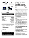
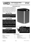
Table 1. Clearances, Unit Dimensions, and Component/Feature Specifications
Clearances
Unit Dimensions
B
A
B
C
D
E
F
in. (mm)
6 (150)
6 (150)
6 (150)
6 (150)
24 (600)
max. 0.2º
angle
A
B
C
F
A
in. (mm)
A 13-1/2 (343)
B 8-1/8 (206)
C 23-3/4 (603)
C
E
Lbs. (kg)
16 (8)
22 (10)
26 (12)
D
Component/Feature
Nominal Specifications/Range
Steam capacity (HCSteam-35)
12 lb/h (5.4 kg/h)
-15%
+10%
Steam capacity (HCSteam-16)
5-1/2 lb/h (2.5 kg/h)
-15%
+10%
Water supply pressure limits
15 psi to 116 psi (0.1 to 0.8 MPa)
--
--
Water supply temperature limits
34F to 104F (1C to 40C)
--
--
Water supply flow minimum
0.12 gpm (0.45 L/min)
--
--
Power supply (HCSteam-35)
230 VAC
-15%
+10%
Power supply (HCSteam-16)
110 VAC
-15%
+10%
Total Drain Water Flow
7 gpm (26.2 L/min)
-10%
+10%
Ambient temperature operating
34F to 104F (1C to 40C)
--
--
Ambient humidity operating
10 to 60% rH
--
--
This humidifier has been designed to directly humidify
ducts using a distribution system. The installation, use and
maintenance operations must be carried out according to
the instructions contained in this manual and on the labels
applied internally and externally.
Disconnect the humidifier from the main power supply
before accessing any internal parts.
The conditions of the environment and the power supply
voltage must comply with the specified values listed on the
data label in the humidifier.
All other uses and modifications made to the humidifier
that are not authorized by Lennox are considered
unauthorized, and Lennox assumes no liability for the
consequences of any such unauthorized use.
Please note that the humidifier contains powered electrical
devices and hot surfaces.
General
WARNING
Before installing or handling the humidifier, please care
fully read and follow the instructions and safety stand
ards described in this manual and on the labels attached
to the HCSteam-16/-35 Residential Steam Humidifier.
NOTICE
Water supply to humidifier cannot be from a hot water
supply.
Using a hot water supply can damage some humidifier
components and will void warranty.
NOTICE
The humidifier requires water to operate.
Do NOT mount it above materials or machinery that
could be damaged if a leak occurs. Lennox assumes no
responsibility for consequential or inconsequential dam
age as a result of any leaks.
If unit must be located where any leaking water could
cause damage, an auxiliary drain pan is recommended.
The
HCSteam-16/-35
humidifier
produces
non-pressurized steam which is then used to humidify the
air.
The quality of the water used affects the operation of this
unit, so the humidifier may be supplied with untreated
water, as long as it is drinkable and not heated, softened or
de-mineralized. The water converted into steam is
automatically replaced through an electric fill valve.
Periodically, based on the water quality, the unit will also
drain some water to dilute the build-up of minerals in the
steam generator.
506746-01
Tolerance
Disposal of Humidifier Parts
The humidifier is made up of metallic and plastic parts. All
parts must be disposed of according to the local standards
on waste disposal.
Page 2
+070222075 rel. 1.3, dated June 2013
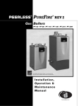
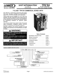
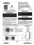
Basic Humidifier Operation
STEAM HOSE ADAPTER
FILL CUP
DRAIN TANK
USER INTERFACE / DISPLAY
STEAM
CYLINDER
WATER
INLET AND
FILTER
FILL VALVE
ON / OFF & SET BUTTONS
TEMPERING VALVE
DRAIN PUMP
Figure 1. Basic Humidifier Components
CAUTION
STEAM
OUTLET
8
SCALDING HAZARD!
The humidifier has heated parts (100C/ 212F).
CYLINDER
FULL PROBE
9
3
FILL CUP
ELECTRODE
7
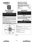
On a call for humidity, the HCSteam-16/-35 humidifier
controller opens the water fill valve (1) and allows water to
enter the cylinder. A flow restrictor (4) prevents the unit
from filling too quickly or with too much pressure. The
water flows up the fill tube (2) and into the fill cup (3). Water
then flows over the dam in the fill cup (3), creating a 1" air
gap that prevents contaminated water backflow into feed
lines. Water then flows through the fill tube (6) and into the
bottom of the steam cylinder (5). Any backflow or overflow
of water travels through the overflow hose (13) to the drain.
HL
STEAM
CYLINDER
5
The HCSteam-16/-35 is an electrode humidifier. It produces
steam for humidification by passing electric current through
metal electrodes (7, figure 2) immersed in water inside a
plastic steam cylinder (5). There are no heating elements.
Steam output is directly proportional to the conductivity of the
water, and the amount of electrode immersed in the water.
13
OVERFLOW
HOSE
2
FILL TUBE
6
FILL TUBE
STRAINER
12
DT
11
DRAIN
PUMP
10
TEMPERING
VALVE
4
FLOW
RESTRICTOR
1
FILL VALVE
Figure 2. Basic Humidifier Operation
As the water fills the cylinder, it will reach the electrodes (7)
and current will begin to flow. As the water continues to fill
the cylinder, the current will increase, and this is monitored
by an amperage transformer connected to one of the
power wires and located on the electronic controller. When
Page 3
HCSTEAM-16/-35 SERIES
the desired current is reached, the fill valve (1) will close
and the water will then begin to warm and produce steam.
If the water reaches the cylinder full probe (9) or if current
rises too much, the drain pump (11) will be activated to
drain away some water and reduce the current flow to
acceptable levels. Note that, any time the drain pump is
activated, the tempering valve (10) will be opened for
tempering the hot drained water down to 140º F (60ºC) in
accordance to local and national standards.
Periodically, based on the incoming water conductivity, the
unit will run the drain pump (11) and drain some water to
reduce the mineral concentration. A strainer (12) in the
cylinder helps to prevent mineral debris from jamming the
drain pump (11).
In case the HCSteam-16/-35 humidifier remains powered
but idle, i.e. without producing steam, for more than 48
hours (2 days), the cylinder will be emptied to not have
stagnant water inside.
If there is no water in the cylinder, there will be no current
flow and no steam production. The electrodes do not burn
out, but they will eventually become completely coated
with mineral and the cylinder will then need to be replaced.
Cleaning cylinders may cause electrode damage,
therefore voiding its warranty. See maintenance section
on Page 21.
Positioning the Humidifier
The HCSteam-16/-35 humidifier has been designed for
on-wall installation. The simplest and most efficient
installation would have the humidifier installed just below
the duct where the steam nozzle is to be installed. This
minimizes steam hose length and the amount of
condensate. Certain clearances must be maintained
around the unit for safety and maintenance (see table
1 on Page 2)..
If present, remove packing as shown in figure 4.
Installation
Installing the Nozzle
The HCSteam-16/-35 humidifier's nozzle must be installed
onto the ductwork near the humidifier. Refer to the Steam
Distribution section (Page 8) for information on how to
properly locate the nozzle, for dimensions for the hole
mounting pattern, and for connections to the humidifier
and to the condensate drain. (Also see figure 6 for a typical
installation diagram.)
Drill a 2-1/4" (57 mm) hole in the ductwork at the selected
location for inserting the nozzle into the duct work. Position
the nozzle in the hole. Mark and drill 1/16" mounting holes
and use self-tapping sheet metal screws to attach the
nozzle to the duct.
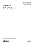
Removing the Humidifier Front Cover
The front cover is secured by four screws located at the
four corners of the unit. Using a Phillips head screwdriver,
loosen the four cover screws and then pull the front cover
away from the back part of the unit (see figure 3).
Installing the Humidifier
REMOVE PROTECTIVE
FILM FROM COVER
Figure 3. Removing the Front Cover
LATCH THE CYLINDER
CLAMP
REMOVE PACK
ING BEFORE IN
STALLING
REMOVE
RESTRAINT
BEFORE IN
STALLING
REMOVE PRO
TECTIVE FILM
FROM DISPLAY
CAUTION
Do not install the humidifier in an location that is within
the reach of children.
If unit must be located where any leaking water could
cause damage, an auxiliary drain pan is recommended.
REMOVE PACKING
BEFORE INSTALLING
Do not install the humidifier in an unconditioned space or
where ambient temperature would be outside humidifi
er's specified operating temperature (attic or crawl
space).
506746-01
Figure 4. Removing Packing
Page 4
+070222075 rel. 1.3, dated June 2013
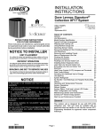
Installing Humidifier on a Wall
Fastening to the Wall—Drill mounting holes in the wall using the installation template; then secure the humidifier firmly to
the wall using the supplied screws and anchors (see figure 5).
CONDENSATE
7/8
(24)
13-7/16
(341)
10-1/8
(257)
5
(128)
2-1/8
(54)
3/8
(9)
2-1/2
(65)
1-7/8
(48)
2-3/4
(70)
2-3/8
(60)
5
(128)
STEAM
1-5/8
(40)
8 (204)
Dimensions in inches (mm)
STEAM
1-1/8 dia. (30)
2-3/4
(70)
MOUNTING
HOLES
1-5/8 dia. (40)
CONDENSATE
23-5/8
(600)
CL
ELECTRICAL
7/8 dia. (23)
2 dia. (51)
2-3/8"
(60)
FILL
DRAIN
2
(51)
5/8 (16)
3-5/8
(92)
3-1/4
(82)
3-7/8
(98)
3-1/8
(78)
1-3/8
(35)
1-1/2 2-1/8
(37) (53)
DRAIN
FILL
ELECTRICAL
4
(102)
2-1/2
(62)
1-1/2 2-3/8
(38) (60)
1-3/8
(36)
17-5/8
(448)
CL
3-7/8
(98)
Figure 5. Installation dimensions and details
Page 5
HCSTEAM-16/-35 SERIES
Installing the Air Proving Switch (included)
IMPORTANT - Failure to install the air proving switch
will void the humidifier warranty!
The air proving switch (Cat. no. Y3786; provided with
humidifier) is a differential pressure switch that is required
to make sure that the blower is running prior to steam
production. Six feet of 3/16" tubing is provided along with
two pressure taps (mounting screws are not included) to
connect both pressure taps to the switch, however, install
the switch first, and then install one pressure tap in only the
supply duct (positive pressure application, step 2. below).
See figure 6.
1. Install Switch and Pressure Tap
Select a mounting location near the supply duct which
will not be subject to vibration or where the switch
could be damaged. Mount the air proving switch in any
vertical plane except with the tubing connections
directed upward.
Connect the normally open terminals on the air proving
switch to the low voltage terminal strip in the
humidifier. See wiring diagrams in figures 14 through
18.
2. Positive Pressure Application — Use the positive
pressure application when large amounts of air flow or
high static is present at the pressure tap in the supply
duct.
Install the duct air sampling tap to the supply duct work
as close to the switch as possible on the positive side
of the blower (see figure 6).
From the 6' tubing provided, cut just enough 3/16"
tubing to reach from the pressure tap to the P1 switch
port. (P2 remains open).
NOTE - Check for closure of the blower switch using
the lowest blower speed setting. If the switch fails to
close the open set of contacts, you must use the
differential application.
3. Differential Pressure Application — Use the
differential pressure application when small amounts
of air flow or low static is present across the pressure
tap.
Install the 2nd pressure tap in the return duct work (see
figure 6).
Use the remaining 3/16" tubing to connect P2 switch
port to the negative pressure tap. Check for closure of
the switch when blower is turned on.
Plumbing
Water characteristic requirements
The humidifier must be supplied with water with the
following characteristics:
S Pressure between 20 psi and 110 psi (0.137 MPa and
0.758 MPa; [1.4 and 7.6 bar])
S Cold water supply
S Flow-rate minimum of 0.21 gpm (0.45 L/m)
S Hardness no greater than 400 ppm3 of CaCO (40º fH)
S Conductivity from 125 to 1250 S/cm
506746-01
S
S
Drinkable and absent of organic compounds
The characteristics of the water supply must fall within
the supply water characteristics outlined in table 2:
Unacceptable Water Types:
NOTICE
Do not connect water supply near the water heater
without using proper plumbing techniques; use a heat
trap. Do not install between an expansion tank and water
heater. Connect only to cold water line.
S
Softened Water—as this will lead to foam, electrode
corrosion and greatly shortened cylinder life.
S Water containing disinfectants or corrosion inhibitors,
as these are potential irritants.
S Industrial water, boiler water or water from cooling
circuits.
S Any potentially chemically or bacteriologically
contaminated water.
S Heated water.
Testing Water
A conductivity
meter is
recommended for
testing the water: Cat # Y3480 (AP-2 AquaPro Water
Quality Tester). Specifications:
EC Range: 0-9999 S.
Temperature Range: 0-80 C; 32-176 F.
Resolution: 1 S; Temp. resolution is 0.1C/F.
Accuracy: +/- 2%
Calibration: Digital calibration by push button.
Housing: Water-resistant.
Power source: 1 x 3V button cell (included) (model
CR2032).
Dimensions: 15 x 2.8 x 1.3 cm (5.9 x 1.1 x .5 inches) .
Weight: 42.5 g (1.5 oz.).
Water Supply Connection
The recommended connection between the fill valve and
the water supply line is by way of the provided fill hose (5'
[1.5 m] hose with one straight 3/4" fitting and one 90
degree 3/4" fitting). The provided hose absorbs water
"hammering" in order to avoid fill valve damage.
The water line may be routed through the back or through
the bottom of the unit. The fitting then threads onto the
valve assembly inlet located on the bottom of the
humidifier (see figure 6) using a 3/4" female hose
connection. Note that there is a strainer built into the fill
valve fitting underneath the unit, which will require periodic
cleaning, so be sure to allow clearance for access.
Page 6
NOTICE
Do not use any thread sealant.
Secure fill hose fittings by tightening ¼ turn past handtight with a wrench.
Do not use hard piping for direct connection to the humid
ifier. Only use supplied flexible fill hose or equivalent.
+070222075 rel. 1.3, dated June 2013
STEAM HOSE
DETAIL A
FILL CUP
STEAM
NOZZLE
SUPPLY
AIR TAP
RETURN
INSTALL TRAP IN
CONDENSATE LINE
PER FIGURE 11.
SUPPLY
STEAM CONDENSATE
RETURN LINE
STEAM HOSE
ADAPTER
AIR PROVING SWITCH
RETURN
AIR TAP
TO RETURN
AIR TAP
(if used)
TO SUPPLY
AIR TAP
DRAIN
LINE
FILL
HOSE
OPEN
DRAIN
SHUTOFF VALVE AND
FILTER (Recommended)
DETAIL A
MIN 5º
slope
Water inlet with filtering
screen (3/4" hose con
nection)
1-1/4" Water drain
WATER FILL HOSE
EXTENSION
TUBE
DRAIN LINE
DRAIN
LINE
OPEN
DRAIN
SUPPLY WATER - COLD WATER
ONLY
SHUTOFF VALVE AND FILTER (Recommended)
DRAIN
LINE
Figure 6. Typical Installation
Page 7
HCSTEAM-16/-35 SERIES
Table 2. Limit Values for Water Supplying the HCSteam-16/-35 Humidifier
Limit Values For Normal Water
Specific conductivity (R,20°C)
Limit Values For Low Salt Content Water
Units
Min
Max
S/cm
350
1250
Specific conductivity (R,20°C)
Hydrogen ions (pH)
Units
Min
Max
S/cm
125
350
7
8.5
Hydrogen ions (pH)
7
8.5
Total dissolved solids (CR)
mg/l
(*)
(*)
Total dissolved solids (CR)
mg/l
(*)
(*)
Dry residue at 180C (R180)
mg/l
(*)
(*)
Dry residue at 180C (R180)
mg/l
(*)
(*)
Total hardness
mg/l CaCO3
100
400
Total hardness
mg/l CaCO3
50
160
Temporary hardness
mg/l CaCO3
60
300
Temporary hardness
mg/l CaCO3
30
100
Iron + Manganese
mg/l Fe + Mn
0.2
Iron + Manganese
mg/l Fe + Mn
Chlorides
ppm Cl-
30
Chlorides
ppm Cl-
Silica
mg/l SiO2
20
Silica
mg/l SiO2
Chlorine residue
mg/l Cl2
0.2
Chlorine residue
mg/l Cl2
0.2
Calcium sulphate
mg/l CaSO4
100
Calcium sulphate
mg/l CaSO4
60
(no
min)
0.2
(no
min)
20
20
(*) Values dependent on the specific conductivity: in general: CR = 0.93 * R, 20C; R180 = 0.65 * R, 20C
Note: There is no relationship between the hardness and conductivity of water.
Water Drain
WARNING
The drain pipe must be free without back pressure. We
recommend an external anti-flooding device (not sup
plied) to protect from faults of external hydraulic circuits.
The HCSteam-16/-35 humidifier also requires a
connection to a drain. The drain line may be routed out the
back or bottom of the unit using the included angle fitting.
The drain line can be 1-1/4" PVC, CPVC or polypropylene
tubing (drain line must be able to withstand 140F water).
The drain line is not glued or otherwise attached to the
humidifier so it must be supported by itself. The humidifier
includes a drain tempering valve that runs whenever the
drain pump runs and flushes cool water into the drain line
to insure the drain water temperature never exceeds
140F (60C).
When only a 1" or 3/4" drain is available, a temporary drain
reservoir can be constructed as shown in figure 7. This is a
field supplied device. Devices such as the one shown have
been tested and are approved to be used with the
HCSteam in the described applications.
The drain water from the HCSteam is diverted into the top
opening of the riser pipe. The figure shown also acts as an
air gap and allows the drain water from the HCSteam to
empty via gravity into the available 3/4" drain.
The reservoir can be constructed from field supplied
plumbing fittings (PVC, CPVC, PEX, etc.) rated for 140 F
drain water applications. The reservoir in the diagram is
constructed with the following:
S 4 in. x 12 in. PVC Sch. 40 DWV plainend pipe
S 4 in. x 2 in. PVC reducing coupling/bushing
S 2 in. x 3/4 in. bushing
S 3/4 in. elbows and valve
If 3 in. pipe is used, it should be at least 21 in. long. The
elbows and valve shown allow more flexibility when
aligning humidifier drain with existing drain line. A drain
trap can also be incorporated into this fixture where
needed.
506746-01
If a condensate pump is required, it must be able to pump
the volume and temperature listed below at the installed
lift. Hartell A5 series condensate pumps are capable of
meeting the pumping requirements up to 24 foot lift.
The drain water characteristics are:
S Drain Rate 7.1 gal/min. (26.8 lit/min.)
S Connection 1-1/4" (32mm)
S Temperature 140F (60C)
Figure 7. Slow / Restricted Drain Lines (3/4”)
Drain Connections
When using a rear outlet drain passing through drywall, we
suggest using a 1-1/4" extension tube. When using a
bottom outlet drain, attach the included 90 fitting to the
drain outlet. The drain outlet may be rotated. Then connect
a 1-1/4" trap adaptor to connect to drain pipe.
Steam Distribution
CAUTION
Do not touch steam hose when humidifier is operating!
The steam hose is a heated part. Allow to cool before
servicing.
Duct Steam Injection
The maximum allowed duct static pressure is 2" w.c.
Page 8
+070222075 rel. 1.3, dated June 2013
The HCSteam-16/-35 humidifier include a plastic injection
nozzle (figure 8).
height
min. 8"
O.D. - 2.2" (56mm);
drill 2-1/4" (57mm)
hole in duct
2-1/2"
(63m)
2-1/2"
(63m)
1/3 height
min. 8"
STEAM
INLET
CONDENSATE
CONNECTION
Figure 8. Plastic Injection Nozzle
A typical installation is shown in figure 6.
NOTICE
centered
Nozzle location is very important to the proper absorp
tion of the steam in the air stream. Select a location ob
serving the following:
S nozzle must be installed in supply duct,
S nozzle location must be easily accessible,
S nozzle location must allow at least 3' (1m) of straight
metal duct without elbows or obstructions,
S duct must be un-insulated interior, and if in uncondi
tioned spaces, insulated exterior,
S clearances shown in figure 9 must be maintained.
Figure 9. Plastic Nozzle Installations
Installing Steam Hoses
NOTICE
Ninety percent (90%) of all operation problems are cre
ated by improper steam piping from the humidifier unit to
the duct steam nozzle.
Installing Return Condensate Hose
The return condensate hose from the nozzle must be
trapped. Coil the hose into a vertical loop and secure it
below the nozzle. This trap prevents steam from being
released into the cabinet. The hose end may be run
through the knockout at the top of the humidifier and be
inserted into the hole located on top of the fill cup. See
figures 6 and 11.
Make the connection between the humidifier steam hose
adapter and nozzle using only the provided hose
(unsuitable hoses may weaken and crack causing steam
leaks).
S Avoid the formation of pockets or traps where
condensate may form.
S Avoid choking the hose due to tight bends or twisting.
S Fasten the end of the hose to the steam hose adapter
on the humidifier and the steam nozzle using metal
hose clamps, so that these do not detach due to the
high temperature.
NO
SLOPE
SAG
NO SLOPE
KINKED
UN
DRAINED
ELBOW
NO TRAP
UN
DRAINED
ELBOW
NO DISTRIBUTION
PIPE DRAIN
Figure 10. Unacceptable Examples of Installing Steam Hoses
Page 9
HCSTEAM-16/-35 SERIES
5 ft (1.5 M) MAX.
>20º
5 ft (1.5 M) MAX.
IF NO SLOPE
3" (.9M) MAX.
>5º
>20º
10 ft (3M) MAX.
5ft (1.5 M) MAX.
DRAINS
GENTLE
BEND
>5º
>20º
TYPICAL INSTALLATION
WHEN UNIT IS ABOVE
THE STEAM NOZZLE
>20º
P-trap
NOTE - Height of traps must be greater than the
duct static pressure
OBSTRUCTION
NOTES Slope piping up in direction of steam flow at 20º or greater (2-1/2" per foot
[63 mm per 305 mm])
Slope piping down in direction of steam flow at 5º or greater (3/4" per foot
[19 mm per 305 mm])
Max. length of rubber steam hose is 10' (3 m)
SUPPORTED STEAM HOSE
AND/OR COPPER PIPE
DRAINS
Figure 11. Installing Steam Hoses
NOTE - Maximum length of rubber steam hose is 10 ft. (3 m). Insulated copper tubing may be up to 20 ft. (6 m) in length. In all
cases, minimize sharp bends and elbows. Use 2 - 45 elbows instead of 90 elbows. Hose inner diameter = 7/8" (22 mm);
Hose outer diameter = 1-1/4" (30 mm).
Insert the power and ground connection cables into the
Wiring
electrical panel compartment using the strain reliefs
supplied (see figure 12, A), and connect to the terminals.
An external fused disconnect must be installed.
Power Wiring
Check that the power supply voltage to be connected
All wiring must be in accordance with local, state and
matches the value indicated on the rating plate inside the
national electric codes.
electrical panel.
Power
Steam
External External
Connect power wires to the power terminal block located at
supply Output
Power
Fuse
(single
lbs/hr
Wire
(A) or
the bottom left of the control module, polarity does not
Model
phase)
(kg/h)
kW
Amps
Gauge
Breaker
matter (see figure 12, B).
110
HCSteam5.5
Connect the ground wire to the unit's chassis ground,
VAC
1.80
16.40
AWG10
25
16
(2.5)
50/60Hz
located just behind the power wiring terminal block (see
230
figure 12, C).
HCSteam12
35
VAC
50/60Hz
(5.4)
3.89
16.95
AWG10
25
L1 L2
WIRE NUT
WARNING
NOTE - Tolerance allowed on main voltage =-15% to
+10%.
506746-01
Page 10
CONTROL
NOTE - To avoid unwanted interference, the power cables
should be kept separate from any control wiring.
GND
POWER
ELECTRIC SHOCK HAZARD!
The humidifier uses electrical power.
Always disconnect the main power before opening or
servicing the humidifier!
L1 L2
STRAIN
RELIEF
A
GND
SERVICE
DISCONNECT
B
C
Figure 12. Power Wiring Connections
+070222075 rel. 1.3, dated June 2013
Control Wiring
The humidifier is controlled by humidistat and safety
devices such as high-limit humidistat, air proving switch,
and remote on/off.
The humidifier is operated by the closing of a mechanical
humidistat, or by the closing of a normally open dry
contact. The most common is a combination of a
humidistat and air proving switch. Diagrams A and B in
figure 13 show the routing to the terminal block.
Connect control devices to humidifier using the diagrams
shown in figures 14 through 18. Following each diagram is
an explanation of the sequence of operation associated
with each wiring configuration.
Air Proving Switch and Safety Switches
Remove the jumper between terminals AB-AB and
connect air proving switch. DO NOT apply any voltage to
AB-AB.
Thread the control wiring through the bottom of the unit,
and the strain relief (see figure 13) and then up the side of
the control module to the top right wiring terminal blocks.
Connect the control wiring to the control wiring terminal
blocks found at the top right side of the control module.
A
B
Figure 13. Routing Control Wiring to Terminal Block
Humidifier
low voltage
wiring panel
N2
GND
N1
AB
AB
GND
IN
NO
C
NC
C
NO
GND
24VAC
S
S
S
S
Required Air Proving
Switch (provided)
(not
used)
C
NO
Alarm
terminals
(if used)
(not
used)
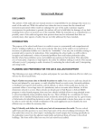
Note 1. Blower interlock is required.
Note 2. 48G96 relay field supplied.
Note 3. Remove factory jumper between AB-AB
Typical Air Handler /
Furnace Control
Thermostat
(AHC or IFC)
Conventional 24 VAC
Humidistat (Cat no.
X9553 or equivalent)
Outdoor AC Unit
48G96 SPDT Interlock Relay
When the humidity in the space falls below the conventional humidistat's RH set point, the circuit closes from "GND" to "IN" on the humidifier
controller and in turn, closes the EXT FAN contacts ("NO" to "C") in the humidifier controller.
Terminal R on the furnace or air handler feeds 24V to the EXT FAN contacts (now closed) and to the blower interlock relay coil. The interlock
relay normally-open contacts close to energize “G" on the furnace or air handler and start the indoor blower (if not already running by a heating
demand). The interlock relay also isolates “G" from the thermostat to prevent a back feed that would start the outdoor unit.
When the indoor blower achieves sufficient speed, the air proving switch contacts close completing the circuit from "AB" to "AB" on the humidifier
controller. Steam production will now start and continue until the humidistat demand is satisfied.
When the humidistat has reached its RH set point, its contacts open stopping steam production. The humidifier controller EXT FAN contacts
open, de-energizing the blower interlock coil and stopping the indoor blower (if not running due to a heating demand or thermostat blower de
mand). When the indoor blower stops, the air proving switch contacts will open.
Figure 14. Humidifier with Conventional 24V Humidistat and Interlocked with HVAC Blower
Page 11
HCSTEAM-16/-35 SERIES
Humidifier
low voltage
wiring panel
N2
GND
N1
AB
AB
GND
IN
(not
used)
SLP98 Furnace /
CBX40 Air Handler
Required Air Proving
Switch (provided)
ComfortSense® 7000
Thermostat
C
NO
Alarm
terminals
(if used)
NO
C
NC
C
NO
(not
used)
48G96 Relay
Outdoor AC Unit
(not
used)
GND
24VAC
S
Note 1. Do not connect “H" on CS7000 to “H" on furnace
or air handler control board.
Note 2. Set up humidifier per CS7000 thermostat installa
tion instructions.
Note 3. 48G96 relay field supplied.
Note 4. Remove factory jumper between AB-AB.
Humidification is controlled by the humidity sensor in the thermostat. When the humidity in the space falls below the thermostat's humidity RH set
point, 24 volts goes on the thermostat's "H" terminal to energize the humidifier isolation relay coil which closes the open set of contacts in the relay,
and completes the circuit between "GND" and "IN" on the humidifier controller.
S
S
The thermostat will also send power to the "G" terminal on the air handler or furnace control to start the indoor blower.
When the indoor blower achieves sufficient speed, the air proving switch contacts close completing the circuit from "AB" to "AB" on the humidifier
controller. Steam production will now start and continue until the humidity demand is satisfied.
S
When the RH set point is reached, the thermostat removes 24 volts from “H" which opens the isolation relay circuit and, in turn, opens the circuit
between "GND" and "IN" on the humidifier controller, stopping steam production. The “G" signal will also be removed to turn off the blower (if not
running due to a heating demand or thermostat blower demand). When the indoor blower stops, the air proving switch contacts will open.
Figure 15. Humidifier with ComfortSense® 7000 thermostat used as Humidistat and Interlocked with HVAC
Blower
Note 1. Humidification must be added in icomfort Wi-Fi®
thermostat during commissioning. Refer to icomfort
Wi-Fi® Installer Guide for details.
Note 2. 48G96 relay field supplied.
Note 3. Remove factory jumper between AB-AB.
Humidifier
low voltage
wiring panel
N2
GND
N1
AB
AB
GND
IN
NO
C
NC
C
NO
GND
24VAC
S
S
S
S
(not
used)
icomfort
Wi-Fi®
thermostat
Required Air Proving
Switch (provided)
C
NO
icomfortt enabled
outdoor unit
Alarm
terminals
(if used)
48G96
Relay
(not
used)
(not
used)
SLP98 / icomfort enabled
CBX40UHV / CBX32MV ONLY
Humidification is controlled by the humidity sensor in the thermostat. When the humidity in the space falls below the thermostat's humidity RH set
point, a demand message for humidification is sent to the HVAC unit control board.
The demand message starts the indoor blower and sends a 24 volt signal from the “H" terminal on the furnace control to the humidifier isolation relay
coil. The isolation relay contacts close to complete the circuit from “GND" and “IN" terminals on the humidifier controller.
When the indoor blower achieves sufficient speed, the air proving switch contacts close completing the circuit from "AB" to "AB" on the humidifier
controller. Steam production will now start and continue until the humidity demand is satisfied.
When the RH set point is reached, the thermostat removes the demand to the furnace board which removes the 24 volt output from the “H" terminal
and opens the isolation relay circuit and, in turn, opens the circuit between “GND" and “IN" on the humidifier controller, stopping steam production.
The indoor blower will be turned off (if not running due to a heating demand or thermostat blower demand).
Figure 16. Humidifier with icomfort Wi-Fi® Thermostat used as Humidistat with an icomfortt enabled SLP98
Gas Furnace or icomfortt enabled CBX40UHV or CBX32MV Air Handler
506746-01
Page 12
+070222075 rel. 1.3, dated June 2013
Note 1. Humidification must be added in icomfort Wi-Fi®
thermostat during commissioning. Refer to icomfort
Wi-Fi® Installer Guide for details.
Note 2. 48G96 relay field supplied.
Note 3. Remove factory jumper between AB-AB.
Humidifier
low voltage
wiring panel
N2
GND
N1
AB
AB
GND
IN
NO
C
NC
C
NO
GND
24VAC
S
(not
used)
icomfort
Wi-Fi®
thermostat
Required Air Proving
Switch (provided)
C
NO
icomfortt enabled
outdoor unit
Alarm
terminals
(if used)
48G96
Relay
(not
used)
(not
used)
SL280 ONLY
Humidification is controlled by the humidity sensor in the thermostat. When the humidity in the space falls below the thermostat's humidity RH set
point, a demand message for humidification is sent to the furnace control board.
S
The demand message starts the indoor blower and closes the "HUM" contacts on the furnace control. 24 VAC passes through a field-installed jumper
from the "R" terminal on the control board, through the closed "HUM" terminals, and to the humidifier isolation relay coil. The isolation relay contacts
close to complete the circuit from "GND" and "IN" terminals on the humidifier controller.
S
When the indoor blower achieves sufficient speed, the air proving switch contacts close completing the circuit from "AB" to "AB" on the humidifier
controller. Steam production will now start and continue until the humidity demand is satisfied.
S
When the RH set point is reached, the thermostat removes the demand to the furnace board which opens the HUM contacts, opens the isolation
relay circuit and, in turn, opens the circuit between "GND" and "IN" on the humidifier controller, stopping steam production. The indoor blower will
be turned off (if not running due to a heating demand or thermostat blower demand).
NO
C
NC
C
NO
GND
24VAC
S
S
S
S
4
3
2
(not
used)
ON
OFF
OFF
1
N2
GND
N1
AB
AB
GND
IN
ON
Humidifier
low voltage
wiring panel
DIP
Figure 17. Humidifier with icomfort Wi-Fi® thermostat used as Humidistat with an icomfortt enabled SL280
Gas Furnace
ON
HC DIGITAL AUTOMATIC HUMIDISTAT
DIP SWITCH SETTINGS FOR HUMIDISTATONLY OPERATION
C
Required Air Proving
NO Switch (provided)
Alarm
terminals
(if used)
Typical Air Handler / Fur
nace Control (AHC or IFC)
Note 1. Blower interlock is required.
Note 2. 48G96 relay field supplied.
Note 3. Set signal type to “1" for modulating (Step 5, Figure
23 [Page 17]).
Note 4. Remove factory jumper between AB-AB.
Note 5. Connected for Modulating Operation.
Thermostat
1
2
5G0
6G
7AOUT
8G0
9NTCE
10DIN
HC Digital
Automatic
Humidistat
(Cat.. no.
Y3760)
Outdoor
Sensor
Outdoor AC Unit
48G96 SPDT Interlock Relay
Steam production is modulated between 20% and 100% of the maximum production proportionally to the signal provided by the humidistat. When
the humidity in the space falls below the humidistat's RH set point, the humidistat sends a 0 to 10Vdc from “7AOUT" terminal to the "IN" terminal
on the humidifier controller and in turn, closes the EXT FAN contacts (“NO" to “C") in the humidifier controller.
Terminal R on the furnace or air handler feeds 24V to the EXT FAN contacts (now closed) and to the blower interlock relay coil. The interlock relay
normally-open contacts close to energize “G" on the furnace or air handler and start the indoor blower (if not already running by a heating demand).
The interlock relay also isolates “G" from the thermostat to prevent a back feed that would start the outdoor unit.
When the indoor blower achieves sufficient speed, the air proving switch contacts close completing the circuit from "AB" to "AB" on the humidifier
controller. Steam production will now start and continue until the humidity demand is satisfied.
When the humidistat has reached its RH set point, its contacts open stopping steam production. The humidifier controller EXT FAN contacts open,
de-energizing the blower interlock coil and stopping the indoor blower (if not running due to a heating demand or thermostat blower demand). When
the indoor blower stops, the air proving switch contacts will open.
Figure 18. Humidifier with HC Digital Automatic Humidistat Connected for Modulating Operation
Page 13
HCSTEAM-16/-35 SERIES
NO
C
NC
C
NO
S
S
S
4
3
OFF
ON
HC DIGITAL AUTOMATIC HUMIDISTAT
DIP SWITCH SETTINGS FOR HUMIDISTATONLY OPERATION
C
NO
Required Air Proving
Switch (provided)
Note 1.
Note 2.
Note 3.
Note 4.
Blower interlock is required.
48G96 relay field supplied.
Remove factory jumper between AB-AB.
Connected for ON/OFF configuration.
1
2
Typical Air Handler /
Furnace Control
Thermostat
(AHC or IFC)
Alarm
terminals
(if used)
GND
24VAC
S
2
(not
used)
ON
OFF
1
DIP
N2
GND
N1
AB
AB
GND
IN
ON
Humidifier
low voltage
wiring panel
5G0
6G
7AOUT
8G0
9NTCE
10DIN
HC Digital
Automatic
Humidistat
(Cat.. no.
Y3760)
Outdoor
Sensor
Outdoor AC Unit
48G96 SPDT Interlock Relay
When the humidity in the space falls below the humidistat's RH set point, the circuit closes humidistat terminals “1" and “2" to complete humidifier
controller circuit to “IN" and “GND" and then closes the humidifier controller EXT FAN contacts ("NO" to “C").
Terminal R on the furnace or air handler feeds 24V to the EXT FAN contacts (now closed) and to the blower interlock relay coil. The interlock relay
normally-open contacts close to energize “G" on the furnace or air handler and start the indoor blower (if not already running by a heating demand).
The interlock relay also isolates “G" from the thermostat to prevent a back feed that would start the outdoor unit.
When the indoor blower achieves sufficient speed, the air proving switch contacts close completing the circuit from "AB" to "AB" on the humidifier
controller. Steam production will now start and continue until the humidity demand is satisfied.
When the humidistat has reached its RH set point, output to the humidifier controller "IN" and “GND" terminals falls to 0 Vdc, stopping steam produc
tion, then opens the EXT FAN contacts which will stop the indoor blower (if not running due to a heating demand). When the indoor blower stops,
the air proving switch contacts will open.
Figure 19. Humidifier with HC Digital Automatic Humidistat Connected for ON/OFF Operation
Interlock between HCSteam-16/-35 Humidifier and
Furnace or Air Handler Fan
The HCSteam-16/-35 humidifier must be connected to an
air proving switch (that is, a device that senses the flow of
air in the duct provided by the furnace or air handler). This
air proving switch should be connected to the remote
enabling input (terminals AB-AB). In some applications a
field-provided limit humidistat (normally closed) may be
installed in series with the air proving switch connected to
terminals AB-AB).
The following sequence of events must occur for
HCSteam-16/-35 to produce steam:
S External humidistat contacts must close between
terminals IN and GND providing a steam
humidification demand.
S The air proving switch NO contacts wired between
humidifier terminals AB and AB must close when
significant air volume is provided to allow the
humidifier to operate.
Table 3. Wiring Connections
Terminals
Functions
Electrical specifications
L1-L2 -GROUND
Power supply and Ground
connections
Power supply 110 VAC 1-phase 50-60Hz 1.86kW or 230 VAC 1-phase 50-60Hz 4.05kW
KEY
Programming port
Connecting to Programming port or supervisor (factory use only)
AB-AB
Remote enabling input
Imposes an external NO contact ; Rmax=300 Ohm; Vmax=33 Vdc; Imax=6mAdc;
humidifier enabled = contact closed
IN-GND
Control signal input
Humidistat connection
NC-C-NO
NC alarm contact
Common alarm contact
NO alarm contact
250V; 8Amp max with resistive load; 4 Amp max with inductive load.
In the event of an active alarm, the alarm LED will come on and the relay is energized.
NO-C
External fan relay
250V; 8Amp max with resistive load; 4 Amp max with inductive load
24-GND
Power for external humidistat
Power supply for external humidistat 24 VAC; 2 Watt
506746-01
Page 14
+070222075 rel. 1.3, dated June 2013
EVF
DP
DT
HL
N2
GND
N1
AB
AB
GND
IN
NO
C
NC
C
NO
Fill valve
Drain pump
Drain tempering valve
High-level sensor
HL
NOT
USED
Programming port
for factory use
(see low voltage
control diagrams
figures 14
through 18 for
control wiring
options)
GND
24VAC
Steam cylinder unit
EVF
DP
DT
Water outlet
ON/ 2
OFF
Button 4
Water inlet
6
8
L1 L2
Connected to
ground
Power supply
110 VAC 1-phase 50-60 Hz
or
230 VAC 1-phase 50-60 Hz
External disconnect to
be installed (not sup
plied); respect local
codes.
For 110 VAC, only
switch the hot wire (not
neutral); for 230 VAC,
switch both hot & neut
ral.
Figure 20. Humidifier Internal Controller Wiring Diagram
Page 15
HCSTEAM-16/-35 SERIES
Start-Up
HCSteam-16/-35 Humidifier Controller
The HCSteam-16/-35 humidifier controller features a
comprehensive information display that shows the
operation of the system at a glance:
1. Display is % of nominal
capacity
2. Maintenance or adjust
ment
3. Display is amperage
(default)
4. Steam is being pro
duced
5. Cylinder filling
6. Foaming
7. Water presence inside
the cylinder
8. Cylinder draining
9. LED icons indicate: left:
operation (green);
middle: power (yellow);
right: alarms (red)
1
2
3
14
4
5
6
7
13
8
9
12
10
operation power alarm
10. Drain button for manual
draining of cylinder and
confirming parameter
values
11. ON/OFF button ("I" de
pressed is the ON posi
tion; “O" depressed is
OFF)
12. Reset button to reset
alarms and access
parameters
13. Level of output: 33%,
66%, 100%
14. Fan relay is activated.
11
Figure 21. Humidifier Controller
WARNING
Before starting, check that the humidifier is in perfect
condition, that there are no water leaks and that the elec
trical parts are dry.
Do not connect power if the humidifier is damaged or
even partially wet!
506746-01
When installation is complete, flush the supply pipe for 10
minutes by piping water directly into the drain, without
sending it into the humidifier; this will eliminate any scale or
residues that may cause foam when boiling.
Pre Start-up Checklist
Before starting the humidifier, the following should be
checked:
S Water is connected, the line has been flushed, and
external valves are open.
S Drain is connected, run to an open drain, and has a
trap under the unit.
S Electricity is connected in accordance with
instructions, local codes and data labels in the unit.
S Make sure all electrical connections to the cylinder are
tight.
S The power fuses are installed and intact.
S All control wiring is complete and tested.
S Air proving switch is wired to close when air flow is
proved.
S Hi-limit humidistat (if used) is wired to open on
humidity rise above setpoint.
S Unit wires have been checked to make sure they and
all connectors are tight from shipping.
S The steam hose(s) are run correctly with no sags or
kinks and sloped properly according to the manual.
S Condensate hoses are run correctly with no sags or
kinks and sloped properly according to the manual.
S An auxiliary drain pan and float switch are installed
under humidifier if humidifier is installed in area where
a water leak could cause damage.
Humidifier Start-up Checklist
S Insure that the external power to the humidifier is on.
S Press the “I" part of the On/Off button IN. The yellow
Power LED (middle) will light. The HCSteam-16/-35
humidifier is now ready to operate.
S With a call for humidity, the humidifier will close its
power relays and send power to the electrodes in the
plastic steam generator. The green Operation LED will
light, indicating that operation has begun.
Operation Checkout
Check that the air proving switch closes on the lowest
blower speed:
S After 10 minutes of operation, check duct for signs of
excessive condensation or wetness by inspecting
inside of duct (using an access door or by removing
the nozzle).
S If wetness exists, increase blower cfm or reduce
humidifier output capacity, see figure 23 on page 17.
Page 16
+070222075 rel. 1.3, dated June 2013
Amperage: the amount of current
flowing through the water causing
the water to heat, boil, and pro
duce steam (default display).
Production %: the amount of
steam being produced (ex
pressed as a percentage of the
humidifier's capacity).
Hour counter, expressed in tens;
for instance, when the display
shows 13 the real hour value will
be between 130 and 139 hours.
(Amperage is repeated)
Figure 22. Displaying Information
Initial Start-up with New Cylinder
Flush the cylinder to remove trace contaminants in the
cylinder and water lines after new installations and after
cylinder maintenance. Flushing prevents contaminants
from causing excessive foaming during initial cylinder
start-up. The cylinder flushing cycle can produce drainage
from the HCSteam beyond the high-capacity condensate
pump tank and pumping capacity when installed in
applications with over a 24 foot lift.
When starting with a new cylinder, you should activate the
cylinder cleaning function as follows:
Operation
Displaying Information
By pressing the “reset/sel" button for 2 seconds, the
display will loop from amperage to production in % of the
maximum production to the hour counter and back to
amperage (see figure 22).
Selecting the Signal Type
NOTE - The HCSteam-16/-35 humidifier is preset for a
manual humidistat with only an ON/OFF feature and
normally does not require any change. Should the need
ever arise to reset it, proceed as follows:
1. Make sure the humidifier
switch is off (press "O" part
of switch).
2. While pressing and HOLD
ING both “reset/sel" and
“drain" buttons, switch the
humidifier back on. DO NOT
release
“reset/sel"
and
“drain" buttons until the
wrench icon blinks; then re
lease both buttons.
1. Switch the humidifier off.
2. While pressing and HOLD
ING both “reset/sel" and
“drain" buttons, switch the
humidifier back on. DO NOT
release
“reset/sel"
and
“drain" buttons until the
wrench icon blinks; then re
lease both buttons.
3. Press “reset/sel" until the display shows
02. DO NOT confirm any value higher than
02. Values of 03 or higher not applicable for
these models. If value is higher than 02,
press “reset/sel" until the display goes
back to the normal operating mode and re
start from step 1.
4. Press and hold “drain" (min
imum 1 second); the display
shows “P1" then the present
signal type and then “set".
3. Press and hold “reset/sel" until the display
shows 04. WARNING: DO NOT confirm
any value higher than 04. If 05 or higher is
displayed, press “reset/sel" until the dis
play goes back to the normal operating
mode and restart from step 1.
4. Press and hold “drain" (minimum 1
second); the cleaning starts.
5. Reset the hour counter as per the instructions on page
18.
During cleaning, the electrodes are powered and water fills
until it touches the high-level sensor or the phase current
equals 20A, whichever occurs first. After either of the
events is detected, the steam cylinder is fully discharged
with the electrodes un-powered (the drain pump and the
drain tempering valve are activated for 3 minutes). Lennox
recommends to perform two cleanings when starting a
new humidifier. After the cleaning ends, the humidifier
starts regular operation. The HCSteam-16/-35 humidifier
is now ready for operation.
Page 17
5. Press “reset/sel" for signal type of 0 or 1:
0 = On-Off humidistat
1 = external 0...10 Vdc modulating signal
humidistat.
6. Press and hold “drain" (minimum 1
second) when done to confirm the new
value of P1 and exit to the normal op
erating mode.
7. Switch the humidifier off.
Figure 23. Selecting Signal Type
HCSTEAM-16/-35 SERIES
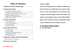
Table 4. Humidification Load Required, Gallon/day [Liter/day] (Ref: AHRI-Guideline F-2008)
Volume of Building ft3 [m3 (approximate)]
Type of
Construction
8000 [227]
10000 [282]
12000 [340]
16000 [453]
20000 [566]
24000 [680]
32000 [906]
40000 [1133]
Tight
4.3 [16]
5.3 [20]
6.4 [24]
8.5 [32]
10.6 [40.2]
12.7 [48.2]
17.0 [64.4]
21.2[80.4]
Average
8.6 [32]
10.6 [40.2]
12.8 [48.4]
17.0 [64.4]
21.3 [80.2]
25.4 [96.5]
34.0 [148]
42.6 [160]
Loose
12.7 [48.3]
15.9 [60.3]
19.1 [72.6]
25.5 [96.6]
31.8 [121]
38.1 [145]
51.0 [193]
63.6 [241]
Legend:
HCSteam-16
HCSteam-35
Changing the Maximum Production Percentage
The maximum production can be adjusted between 20%
and 100% of the nominal production in steps of 5% in order
to suit either the 110 VAC or 230 VAC unit. Default settings
are factory set at 100% (110 VAC unit) 70% (230 VAC unit).
Adjust capacity per humidity calculation or system
application air flow. Table 4 shows the humidification load
requirements. This chart will be helpful in setting the
correct production percentage.
1. Switch the humidifier off.
Resetting the Hour Counter
The hour counter must be reset every time the cylinder is
changed in order to reset and restart the internal
maintenance timer:
1. Switch the humidifier off.
2. While pressing and HOLD
ING both “reset/sel" and
“drain" buttons, switch the
humidifier back on. DO NOT
release
“reset/sel"
and
“drain" buttons until the
wrench icon blinks; then re
lease both buttons.
3. Press “reset/sel" until the display shows
03. DO NOT confirm any value higher than
03. Values of 04 or higher not applicable for
these models. If value are higher than 03,
press “reset/sel" until the display goes
back to the normal operating mode and re
start from step 1.
2. While pressing and HOLD
ING both “reset/sel" and
“drain" buttons, switch the
humidifier back on. DO NOT
release
“reset/sel"
and
“drain" buttons until the
wrench icon blinks; then re
lease both buttons.
3. Press “reset/sel" until the display shows
01. DO NOT confirm any value higher than
01. Values of 02 or higher not applicable for
these models. If value is higher than 01,
press “reset/sel" until the display goes
back to the normal operating mode and re
start from step 1.
4. Press and hold “drain" (min
imum 1 second); the display
shows “P0" then the current
maximum production percent
age and then “set".
5. Press “reset/sel" to change the
Maximum Production in steps of
5% between 20% and 100%.
6. Press and hold “drain" (minimum 1
second) to confirm the new maximum
production percentage and exit to the
normal operating mode.
Figure 24. Changing Maximum Production
Percentage
506746-01
Exceeds capacity of HCSteam units
4. Press and hold “drain" (minimum 1
second) to confirm: the hour counter
will be reset at once and
HCSteam-16/-35 humidifier will go
back to the normal operating mode.
Figure 25. Resetting Hour Counter
Activating the Manual Drain
Press and hold the “drain" button on the front of the unit
until the cylinder is drained.
NOTE - Water will continue to flow from the tempering
valve after the cylinder is empty. Draining should take
around 20 seconds if the cylinder was full.
Sequence of Operation
For a complete description of how the humidifier operates
using the various control devices, see the wiring section
(page 11 through page 13).
Page 18
+070222075 rel. 1.3, dated June 2013
Alarms
In the event of an alarm, the red alarm LED ( ) will flash, the alarm relay will energize and the alarm code will flash in the
display. Multiple alarms will flash in sequence, alternating with the main display. Pressing the “reset/sel" button for 2
seconds will reset the alarms, although still active alarms will continue to display.
Alarms
Display
--
Description
Action
Red Alarm Symbol
Remote on-off open.
Unit disabled.
Off
EE
Internal memory error.
Unit disabled.
On
E0
Control board configuration not
valid.
Unit disabled.
On
Notes
Replace control for EE & E0
E1
High current alarm.
Unit disabled.
On
Turn off, check connections,
check cylinder (no limescale
bridges between electrodes,
no electrodes short-circuited).
Use a ohm-meter to check
whether they are shortcircuited. Look through the
steam outlet to see whether
the electrodes are loose.
E2
Low production, low supply
water conductivity or
excessive foam/limescale in
the cylinder.
Unit disabled.
Press “reset/sel" key for 1
seconds to reset.
On
Check supply water
conductivity (too low?), replace
the cylinder.
E3
Cylinder almost exhausted,
already used for 2000 hrs.
Press “reset/sel" key for 1
seconds to reset.
Off
Change cylinder (not urgent).
E4
Fill alarm, unable or slow fill
(current does not increase
within timeout).
Press “reset/sel" key for 1
seconds to reset, otherwise
the warning will be reset
automatically every 10 minutes
until the supply water is
available again.
On
Check water supply, water inlet
strainer, and fill valve; check
drain pump for leakage.
E5
Drain alarm, unable to drain
(current does not decrease
within timeout).
Press “reset/sel" key for 1
seconds to reset.
On
Check drain pump operation;
check drain connection.
E6
Cylinder exhausted
(critical performance detected).
The warning is automatically
reset if HCSteam-16/-35 can
produce the demand,
otherwise turn off and then on.
Off
Change cylinder (urgent).
E7
Foam detected.
Press “reset/sel" key for 1
seconds to reset.
Off
If it continues, perform some
cleaning cycles (read section
“Initial Start-up with a new
cylinder, Page 16)".
E8
Cylinder lifetime expired (3000
hours).
Unit disabled.
Reset the hour counter (read
section “Resetting the hour
counter").
On
Change the cylinder.
E9
High controller temperature
(above 176 F / 80 C).
The warning is automatically
reset if the temperature
decreases below 176 F / 80
C.
Off
Check the ambient
temperature near the
controller, replace the
controller if the temperature is
OK.
Page 19
HCSTEAM-16/-35 SERIES
Troubleshooting
Problem
Causes
Solutions
The humidifier
does not turn on
1. No electrical power.
2. On/off switch of the humidifier in position “O" (OFF).
3. Control connectors improperly connected.
4. Power source failure; blown fuse; tripped breaker.
5. Transformer failure.
1. Check the safety devices upstream from the humidifier and
the presence of power.
2. Close the switch on the panel: position “I" (ON).
3. Check that connectors are properly inserted in terminal block.
4. Check the power source; check condition of fuses; check for
tripped breaker.
5. Check for proper voltage across 24VAC and GND on control.
If no voltage present, replace controller.
The humidifier
does not start
operation
1. Remote ON/OFF contact open.
2. The humidistat has not been connected correctly.
3. Humidistat failure.
4. Control signal not compatible with the type set.
5. Value measured by the humidistat sensor(s) higher than the
corresponding RH set point.
6. Low conductivity water.
1. Close ON/OFF contacts.
2. Check the external connection.
3. Replace the humidistat.
4. Confirm for correct signal type for connected humidistat using
Selecting the signal type procedure on Page 17.
5. Using RH meter, confirm accuracy of RH sensor(s).
6. If 230 VAC humidifier, consider installing the Low Conductivity
cylinder (Y3484) listed on Page 23.
The humidifier fills
with water without
producing steam
1. High steam back pressure.
2. Fill valve strainer clogged.
3. Mineral buildup in the fill cup.
1. Check that the steam hose is not kinked or sagging, trapping
condensate.
2. Clean the fill valve strainer.
3. Clean the fill cup.
1. Check that the steam nozzle is installed correctly.
1. The steam nozzle is not installed correctly (too near the top of 2. Increase air flow in duct or decrease maximum steam
The humidifier wets
production setting (see Page 17).
the duct or the condensate return is blocked).
the duct
2. Air flow rate is too low.
3. Check the connection of the device (flow switch or differential
pressure switch) controlling the humidifier to the ventilation in
3. Humidifier active when the fan in the duct is off.
the duct.
1. The humidifier drain is blocked.
2. The supply water or overflow circuit has leaks.
The humidifier wets
3. The condensate drain pipe does not bring the water back to
the floor below
the drain pan.
4. The steam hose is not properly fastened to the cylinder.
1. Clean the drain assembly and pan.
2. Check the entire water circuit.
3. Check the correct position of the condensate drain hose in
the drain pan.
4. Check the fastening of the hose clamps on the steam outlet.
Water in the
1. Minerals in the cylinder have over concentrated and are
cylinder turns black
deteriorating the electrodes.
1. Check for sags & kinks that could trap condensate in the
steam hoses that could cause a back pressure on the
cylinder.
2. Check the duct static pressure.
3. Check the fill valve and inlet strainer.
4. Check the drain pump operation.
5. Correct installation problems and replace cylinder.
Heavy arcing
1. The feed water contains large amounts of Iron, Copper or
occurs within hours
other conductive contaminants.
of startup
1. If you are using a softener, discontinue use.
2. Check the electrodes in the cylinder to be sure they were not
damaged in shipping. Use a ohm-meter to check whether they
are short-circuited. Look through the steam outlet to see
whether the electrodes are loose.
Humidifier
continuously fills
and drains without
producing steam
506746-01
1. Mineral has bridged between the electrodes.
2. There is back pressure from the steam hoses or duct.
3. The flow regulator in the fill valve is broken or out of place.
4. Water conductivity is very high.
5. Water is foaming excessively.
Page 20
1. Perform cleaning cycles or replace the cylinder.
2. Check the steam hoses for kinks or gullies that might be
trapping condensate.
3. Replace the fill valve (stuck open).
4. Consider using a mix of demineralized water with raw water.
5. Check cylinder - replace if exhausted.
+070222075 rel. 1.3, dated June 2013
Maintenance
Cleaning the supply, fill, and overflow pipes—Check
that the piping is clear of obstructions; clean or replace if
necessary.
After replacing or checking the plumbing, check that all
components have been reconnected correctly using the
proper seals. Re-start the humidifier and perform 2 or 3
cleaning cycles (see section “Starting with a new
cylinder"), then check for any water leaks.
WARNING
Electrical shock hazard!
Always disconnect the main power before performing
maintenance on the humidifier!
The humidifier and its cylinder contain live electrical
components and hot surfaces, and therefore all service
and/or maintenance operations must be performed by
expert and qualified personnel, who are aware of the ne
cessary precautions. Remove the cylinder from the hu
midifier only after having drained it completely using the
manual “drain" button or procedure. Check that the mod
el and the power supply voltage of the new cylinder cor
respond to the data on the rating label.
WARNING
Always disconnect the main power before touching the
cylinder in the event of leaks, as current may flow
through the water.
NOTICE
It is recommended that during the off-season or long in
activity, the unit is drained of water, the water supply
turned off and the unit is powered down.
Recommended Periodic Checks
S After one hour of operation: Check that there are no
water leaks.
S Every fifteen days or no more than 300 operating
hours: Check operation, that there are no water leaks
and the general condition of the cylinder. Check that
during operation there is no arcing between the
electrodes.
S Every three months or no more than 1000 operating
hours: Check operation, that there are no water leaks
and, if necessary, replace the cylinder. Check that
there are no blackened parts of the cylinder. If there
are blackened parts of the cylinder, check the
condition of the electrodes, and if necessary replace
the cylinder.
S Annually or no more than 2500 operating hours:
Replace the cylinder.
Maintenance of Plumbing Components
WARNING
When cleaning the plastic components do not use deter
gents or solvents.
Cleaning the fill valve—Disconnect the cables and the
hoses. Remove the valve and check the condition of the
inlet filter. Clean, if necessary, with a soft brush and warm
water.
Cleaning the drain pump—Remove the valve body.
Clean, if necessary, with a soft brush and warm water.
Cleaning the drain pan—Clean the drain pan of any
mineral deposits and check that the water flows freely from
the pan to the drain at the drain pump.
Cylinder Maintenance
The life of the cylinder depends on a number of factors,
including the amount and type of mineral in the water, the
correct use and sizing of the humidifier, and the output, as
well as careful and regular maintenance. Another factor
affecting cylinder life is Maximum Production—the higher
the production rate, the shorter the cylinder life; for this
reason, the HCSteam-35 humidifiers is preset from the
factory at 70%. Further reductions in maximum production
will extend cylinder life.
Replacing the Cylinder
WARNING
Scalding hazard!
The cylinder may be hot. Allow it to cool before touching
it or wear protective gloves.
To replace the cylinder:
1. Completely drain the cylinder by pressing and holding
the “drain" button for 15 seconds until the cylinder is
empty.
2. Turn the humidifier off and disconnect the main power.
3. Remove the cover.
4. Loosen the hose clamp and slip the steam hose from
the steam hose adapter.
5. Loosen two screws that hold the steam hose adapter
onto the back wall of the humidifier; then slide the
adapter up from the cylinder and remove; flip up the
cylinder holding bracket and lift up on the cylinder.
6. Disconnect the electrical connections from the top of
the cylinder.
7. Carefully remove cylinder from the pump manifold.
Make sure the O-ring remains in the manifold (see
figure 27).
8. Verify cylinder model/voltage first. Then install the new
cylinder in the humidifier by performing the previous
operations in reverse.
9. Perform initial start-up with new cylinder as provided
on page 17.
Page 21
HCSTEAM-16/-35 SERIES
WARNING: RISK OF BURNING/FIRE HAZARD
NOTICE
Firmly tighten the nut
(44 in-lbs +10% / 5 Nm +10%)
Do not tighten the hose clamp so tight that it crushes the
cylinder adapter outlet.
Electrical connections to the cylinder must be tight or
possible fire hazard may result. Threaded nuts on power
wires must be torqued to 44 in-lb +10% (5 Nm +10%).
See diagram below for proper installation.
WARNING!
DO NOT OVERTIGHTEN TERMINAL NUTS
STEAM HOSE ADAPTER
STEAM HOSE
REMOVED
STEAM HOSE
ADAPTER
REMOVED
CYLINDER
HOLDING
BRACKET
DRAIN
BUTTON
STEAM
CYLINDER
Figure 26. Figure 27. Replacing the Cylinder
506746-01
Page 22
+070222075 rel. 1.3, dated June 2013
Table 5. Replacement Parts
Item
1
2
3
5a,b
6
7
8
9
Part No.
Description
STEAM CYLINDER
Y3481
CYLINDER STD. CONDUCTIVITY 110-120/1 5.5 LBS/HR MODELS
Y3482
CYLINDER STD. CONDUCTIVITY 220-240/1 12 LBS/HR MODELS
Y3484
CYLINDER LOW CONDUCTIVITY 220-240/1 12 LBS/HR MODELS
Y3773
CONTROL MODULE 5.4 kg/h 220-240 VAC
Y3774
CONTROL MODULE 2.5 kg/h 110-120 VAC
—
Y3775
13
12
8
1
ON/OFF SWITCH (special order)
FILL (5a) & DRAIN TEMPERING VALVE (5b) 110-120 VAC
Y3776
FILL (5a) & DRAIN TEMPERING VALVE (5b) 220-240 VAC
Y3777
DRAIN PUMP 110-120 VAC
Y3778
DRAIN PUMP 220-240 VAC
Y3779
90 DEGREE DRAIN ELBOW
2
9
3
5b
FILL CUP + PLUG
FILL CUP HOSE
6
DRAIN HOSE
10
11
12
13
Y3780
COVER HOLDING SCREWS (4 USED)
5a
DRAIN PAN
11
7
10
DRAIN TANK + PLUG
Y3801
STEAM CYLINDER HOSE ADAPTER
Other replacement parts and accessories:
S
S
S
S
S
S
Steam Hose (10' Y3782)
Steam Condensate hose 10' (Y3783)
Fill Hose (Y5880)
Air proving switch (Y3786)
HC Digital Automatic Humidistat (Y3760)
S
S
icomfort Wi-Fi® thermostat
Steam Nozzle (Y3781)
ComfortSense® 7000 thermostat (Y2081)
Table 6. Technical Specifications
Steam flows, VAC, kW
5.5 lbs/hr (2.5 kg/h): 110 VAC 1-phase 50-60 Hz, 1.86 kW
12 lbs/hr (5.4 kg/h): 230 VAC 1-phase 50-60 Hz, 4.05 kW
Steam pressure
3.81 in w.c. / 950 Pa
For duct only.
Dimensions (mm )
24" x 14" x 8" (600 x 341 x 204 mm)
(Height x Width x Depth)
Weight empty / packaged / installed with
water
18 / 22 / 26 lbs. (8 / 10 / 12 kg)
Electrode power cables
12 AWG
Power relays
2 x 30 Amp
Ground connection
Screw
Input water type
Potable water
No demineralized or softened water.
Conductivity range
125-1250 S/cm
Special cylinder for low conductivity
<350 (for 230 volt model only).
Water fill connection
3/4" female water hose connection
Adapter to ¾" FPS..
Water fill - instant flow
0.09 – 0.16 gpm (0.35 – 0.60 l/min)
Drain connection
1.25" O.D. (32 mm)
Adjustable from horizontal to
downward. May be from back or
bottom of unit.
Drain water temp
< 140F (< 60C)
Drain tempering device.
Drain flow
Max 7.1 gpm (max 26.8 l/min)
Ambient indoor operating and storage
temperatures and humidity (outdoor
installation not valid)
Operating temperature:
Operating relative humidity:
Storage temperature:
Storage relative humidity:
Notes
On board.
34F to 104F (1C to 40C)
10 to 60% RH
14F to 158F (-10C to 70C)
5 to 95% rH
Page 23
Storage conditions only apply to HC
Steam units prior to installation.
HCSTEAM-16/-35 SERIES