1
INSTALLER'S GUIDE
2
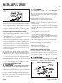
BASEPAN TAB REMOVAL
▲
CAUTION: In scroll compressor applications,
dome temperatures may be hot. Do not touch top of
compressor, may cause minor to severe burning.
The units are factory charged with the system charge required
when using fifteen (15) feet of connecting line. Unit nameplate
charge is the same.
Final refrigerant charge adjustment is necessary. Use the
Charging Charts in the outdoor unit Service Facts.
1. Determine the most practical way to run the lines.
2. Consider types of bends to be made and space limitations.
3. Avoid locating the unit where condensation and freezing of
defrost vapor may annoy the customer. For instance, installing
the unit under a bedroom, kitchen, or picture window may be
annoying to the customer since condensate and fog will occur
during the defrost cycle.
NOTE: Large diameter tubing will be very difficult to rebend once
it has been shaped.
4. Avoid locating the unit under the eaves or other overhead
structures as sizeable icicles may form and the unit may be
damaged by these falling icicles.
4. Provide a pull-thru hole of sufficient size to allow both liquid
and gas lines.
B. LOCATION AND PREPARATION OF THE UNIT
6. Uncoil the tubing — do not kink or dent.
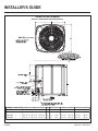
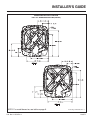
1. When removing unit from the pallet, notice the tabs on the
basepan. Remove tabs by cutting with a sharp tool as shown
above in Figure 2, and slide unit off of pallet.
7. Route the tubing making all required bends and properly
secure the tubing before making connections.
2. The unit should be set on a level support pad at least as large
as the unit base pan, such as a concrete slab.
3. Determine the best starting point for routing the refrigerant
tubing — INSIDE OR OUTSIDE THE STRUCTURE.
5. Be sure the tubing is of sufficient length.
8. To prevent a noise within the building structure due to
vibration transmission from the refrigerant lines, the following
precautions should be taken:
3. The support pad must NOT be in direct contact with any
structure. Unit must be positioned a minimum of 12" from any
wall or surrounding shrubbery to insure adequate airflow. Clearance must be provided in front of control box (access panels) &
any other side requiring service access to meet National Electrical Code. Also, the unit location must be far enough away from
any structure to prevent excess roof runoff water from pouring
directly on the unit. Do not locate unit(s) close to bedroom(s).
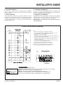
a. When the refrigerant lines have to be fastened to floor
joists or other framing in a structure, use isolation type hangers.
4. The top discharge area must be unrestricted for at least
five (5) feet above the unit.
D. SERVICE VALVE OPERATION
5. When the outdoor unit is mounted on a roof, be sure the roof
will support the unit’s weight. Properly selected isolation is
recommended to prevent transmission to the building structure.
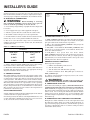
6. The maximum length of refrigerant lines from outdoor to
indoor unit should NOT exceed eighty (80) feet.
7. If outdoor unit is mounted above the air handler, maximum
lift should not exceed twenty-five (25) feet (suction line). If air
handler is mounted above condensing unit, maximum lift should
not exceed twenty-five (25) feet (liquid line).
8. Locate and install indoor coil or air handler in accordance
with instruction included with that unit.
C. INSTALLING REFRIGERANT LINES
▲
CAUTION: If using existing refrigerant lines
make certain that all joints are brazed, not soldered.
b. Isolation hangers should also be used when refrigerant
lines are run in stud spaces or enclosed ceilings.
c. Where the refrigerant lines run through a wall or sill, they
should be insulated and isolated.
d. Isolate the lines from all ductwork.
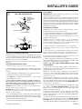
BRASS LIQUID LINE SERVICE VALVE
The Brass Liquid Line Service Valve is factory shipped in the
seated position to hold factory charge. The pressure tap service
port (when depressed) opens only to the field brazing side of the
valve when the valve is in the seated position. The liquid line
valve is not a back seating valve (see WARNING below).
▲
WARNING: Extreme caution should be exercised when opening the Liquid Line Service Valve. Turn
valve stem counterclockwise only until the stem contacts
the rolled edge. (See Figure 3) No torque is required.
3
LIQUID LINE SERVICE VALVE
Condensing units have provisions for braze connections.
Pressure taps are provided on the service valves of outdoor unit
for compressor suction and liquid pressures.
The indoor end of the recommended refrigerant line sets may be
straight or with a 90 degree bend, depending upon situation
requirements. This should be thoroughly checked out before
ordering refrigerant line sets.
The gas line must always be insulated.
PAGE 2
Pub. No. 11-BC11D1-2