1
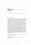
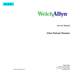
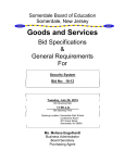
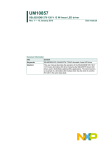
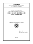
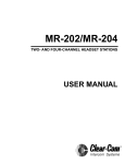
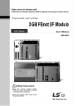
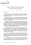
Page 1
SPECTECH
ST150 Nuclear Lab
Station
Operating and Service Manual
Model ST150 Nuclear Lab Station
The ST150 Nuclear Lab Station provides a self-contained unit that
includes a versatile timer/counter, GM tube, sample stand, and an 11 piece
absorber set. The unit comes complete with a serial interface to either
Macintosh or IBM compatible personal computers.
High voltage is fully variable from 0 to +800 volts. The supply is fully
regulated and controlled by the processor for digital accuracy and readout on
the display. Extra large LED's are used for the digital display for clear visual
readout under widely differing ambient light conditions with leading zero
suppression for clarity.
Classroom demonstrations and nuclear experiments may now be run
directly from an IBM-PC or Apple Macintosh compatible computers using the
on-line serial DATALINK built into the ST150 and the NUCLAB emulation
software. Counting functions may be initiated from the ST150 or the
computer. The software supplied produces computer screen displays of all
functions including analog and digital emulation of a ratemeter. Real-time data
is automatically transferred to the computer and stored in spreadsheet
compatible files. Data analysis and graphical presentation are now possible
using many common spreadsheet programs bringing new techniques to
Nuclear Science education.
An AC to DC line converter is supplied for continuous benchtop
operation.
Warranty
Spectrum Techniques warrants products of our manufacture against defects in
workmanship or material for a period of one year from date of shipment. We
will repair or replace at our option, any instrument that is deemed to be
defective during this period. This warranty fully covers all replacement parts
and labor. The instrument must be returned to our factory prepaid and we in
turn will pay the cost of return shipping .
This warranty does not cover damage caused by mishandling or misuse. GM
tubes with broken windows are specifically excluded from this warranty.
Accessory items not manufactured by Spectrum Techniques but supplied as
part of our systems will be subject to the original manufacturers warranty.
April 1996
Page 2
Specifications.
Input:
Built in Geiger Mueller tube: 15 mm diameter, 1.52 mg/cm.² window, 500V operating, 150V plateau.
High voltage:
0 to +800 volts, digitally selectable in 20 volt
increments.
Display:
6-decade LED, 1 in. numerals. Displays counts,
time, and high voltage.
Modes:
Count for preset time, set and view preset time, and
set and view high voltage 0-800v.
Data Link:
DB-9 male connector accepts RS-232 serial cable to
IBM-PC compatible, and DB-9 female accepts DIN
cable for Macintosh computers.
Absorbers:
11 piece set, 6-7400 mg/cm².
Sample holder:
6 position, 1cm spacing.
Power:
Input 9 volt DC, at 500mA from AC adapter.
Specify 110-120, 220-240 VAC at time of order.
Dimensions:
10 in. W, x 7.5 in. H, x 6.2 in. D.
Software supplied:
ST150 Nuclear Lab - PC emulation DOS program
runs with or without Windows on most IBM
compatible PC's. Requires EGA or better graphics
capability.
Optional Macintosh software runs under MultiFinder under System 6.0 and later and also runs
under System 7.x.
All software provides real-time display of simulated
analog or digital ratemeter in CPM or CPS, count,
elapsed time, preset time, high voltage setting,
acquisition time, and run number. Data is saved to
spreadsheet compatible files. Bi-directional control
offers computer control of count start/stop and data
transfer.
Page 3
Operation
Page 3
CAUTION
The detector window is extremely thin and
fragile. If broken it cannot be repaired and will
not be covered under the warranty. Never allow
objects to touch the window.
Page 4
Operating Modes and Controls.
COUNT. This is the normal operating mode where the display registers the
number of radiation events detected by the GM tube. Before starting a count, a
preset time may be entered using the TIME and UP/DOWN buttons. To begin
the count interval press the COUNT button. Any existing count and elapsed
time will be automatically cleared. If a preset time has been entered, the unit
will count until the preset time is reached.
General.
STOP. This button will stop the current count.
The ST150 Radiation Counter may only be operated with the AC
adapter provided or with one of identical specifications. The sample holder
provides six positions with 1 cm. separation between each for placement of
radioactive sources and absorbers. 11 absorbers are provided for use in
radiation absorption experiments. Absorbers may be placed in empty sample
holder slots between the source and the detector.
TIME. If the operator wishes to count radiation events for a predetermined
time, a preset time may be entered by pressing TIME and entering the required
counting time in seconds using the UP/DOWN buttons. To return to count
display mode press TIME again.
Detectors.
HIGH VOLTAGE. The high voltage setting on the GM tube may be set by
pressing the H.V. button. The current setting will be displayed. The high
voltage may be adjusted in 20 volt increments using the UP/DOWN buttons
between 0 and 800 volts. To return to count display mode press H.V. again.
Geiger-Mueller tubes produce electrical pulses when ionizing
radiation events occur within their sensitive volume. For proper operation,
these detectors should be run at a predetermined operating voltage specified by
the manufacturer or derived empirically. To improve sensitivity to alpha and
beta particle radiation, many GM tubes have extremely thin entrance windows
which require considerable care in handling. Do not allow any object to come
in contact with the GM tube mounted in the top of the sample holder. T h e
ST150 includes a fully adjustable high voltage power supply to cover a wide
range of applications. The high voltage level may be displayed on the digital
readout by pressing the H.V. button once. Adjustments to the high voltage
may then be made in 20 volt increments using the UP/DOWN buttons. To
return to count display mode press H.V. again.
Page 5
Page 6
Operation.
GM Plateau.
Basic operation of the model ST150 Radiation Counter is
straightforward and intuitive.
The correct operating voltage for the Geiger-Mueller tube may be
determined experimentally using a small radioactive source such as Cs-137 or
Co-60. A properly functioning tube will exhibit a "plateau" effect, where the
counting rate remains nearly constant over a range of applied voltage. Place the
radioactive source close to the window of the GM probe and slowly increase
the high voltage until radiation events just begin to be detected. Now increase
the voltage in 20 volt steps recording the counting rate at each increment. The
rate should remain fairly constant over a range of voltage and then increase
rapidly as the high voltage is further raised indicating that the tube is entering
the breakdown region. Do not continue to operate the tube in this breakdown
condition but reduce the high voltage and make a plot of the counting rate
versus the applied voltage. The recommended operating voltage may now be
determined as the center of the plateau region. In the example below note that
the plateau extends from approximately 350V to 600V. A reasonable operating
voltage in this case would be 500V.
If no other presets are required, press H.V. again to return to the count
display mode. Operation may now be controlled with the START and STOP
buttons. Pressing TIME will display the acquisition time in seconds.
To count for a preset time, press the TIME button and enter the
required counting time in seconds using the UP/DOWN buttons. Once set the
preset time will remain unchanged unless the UP/DOWN buttons are pressed
again. Start the count with the COUNT button. The count may be stopped
before the preset time is reached by pressing the STOP button. Once the preset
time is reached the counter will stop accumulating data. At this point it is only
necessary to press COUNT to restart the next cycle as the preset will
automatically be restored and the count register reset to zero. If the ST150 is
linked to a computer running the NUCLAB software, data will be
automatically transferred to the computer whenever a count stops either by
reaching the preset time or pressing the STOP button. If however, the count is
stopped by remote control from the computer the data is NOT automatically
transferred. This allows a single run in a multiple run experiment to be
repeated before it is stored.
GM Plateau
6000
5000
4000
Counts
First set the high voltage to the recommended value for the GM tube
using the H.V. and UP/DOWN buttons.
3000
2000
1000
0
0
200
400
600
High Voltage
800
1000
Page 7
Page 8
Resolving Time.
Applications.
Geiger-Mueller tubes exhibit dead time effects due to the
recombination time of the internal gas ions after the occurrence of an ionizing
event. The actual dead time depends on several factors including the active
volume and shape of the detector and can range from a few microseconds for
miniature tubes, to over 1000 microseconds for large volume devices.
When making absolute measurements it is important to compensate
for dead time losses at higher counting rates. If the resolving time of the
detector is known, the true counting rate may be calculated from the measured
rate using the following expression:
The ST150 may be used for a variety of applications some of which
are listed below.
Surface contamination measurement.
Plotting a GM plateau.
Radiation background measurement.
Natural radioactivity.
n= m/1-mt
GM resolving time.
where n is the true counting rate, m the measured rate, and t the detector
resolving time.
If the detector resolving time is unknown, it may be determined
experimentally using two radioactive sources. Maintaining constant counting
geometry is important throughout the experiment. A special source split into
two halves is available for making the measurement, but good results may be
obtained by careful positioning of two standard check sources. With the high
voltage correctly set for the GM tube, position the two sources (a+b) side by
side to obtain a count rate of at least 10,000 CPM. Accurately record the
Detector efficiency.
Radiation absorption studies.
Backscattering.
Inverse square law.
Isotope half life.
countrate as R(a+b). Remove source (b) and record the count rate as R(a).
Carefully replace source (b) to its original position, remove source (a) and
Radiation properties.
record the count rate of source (b) as R(b). The resolving time is given by
Counting statistics.
R(a)+R(b)-R(a+b)
T=
2R(a).R(b)
The resolving time of the ST150 Nuclear Lab Station is very short
and is not a significant factor compared to that of the GM tube.
Page 9
Page 10
NucLab Nuclear Lab Station Software for IBM PC Compatibles
Maintenance.
CAUTION
Dangerous voltages can exist inside the
ST150 from the high voltage power supply.
Before removing the cover ensure the
instrument is in the OFF position and the
high voltage is set to zero. Only qualified
technicians should attempt any repairs.
Your ST150 Radiation Counter is supplied with a computer
communication and control software package named NUCLAB. Command
and data are transferred via the standard RS 232C serial port, and require
connection to the computer’s COM 1 or COM 2 port. NUCLAB allows
counting control of the ST150 from either the front panel buttons or the
computer system.
To run NucLab insert the program disk supplied into drive A, type A:
NUCLAB and the following screen will appear:
Your ST150 has been built with care using quality parts and should
not require any routine service. In the unlikely event of a malfunction, the unit
may be returned to the factory for repair. We will gladly supply a cost estimate
if the warranty period has expired.
A complete list of parts is included for your convenience. Please
contact our customer service department for pricing and availability. In many
instances substitute parts may be used providing they meet or exceed the
original specifications.
Select the appropriate COM port and continue. The COUNT and
STOP controls on the ST150 front panel are repeated on the main NucLab
screen and will remotely control those operations on the unit. Other features of
the software are invoked from their selection within the menu system. Features
and menu selections are made by clicking on the selection with a mouse or by
pressing the key corresponding to the underlined character in the selection.
Page 11
Page 12
NucLab contains an on-screen help menu for guidance through the
basic operations. The Help system provides hypertext allowing topics to be
quickly accessed. To invoke the Help system choose Help Contents from the
Help menu bar selection. Click on any highlighted text to see an explanation
of the feature. Highlighted text may also be selected by pressing TAB until the
desired selection is indicated.
the number of entered runs have completed. When all of the desired data has
been collected, the data may be saved to a spreadsheet compatible text file by
choosing the Save selection from the File menu. The extension defaults to .
TSV to indicate a Tab Separated Value file format. This format allows the
collected data to be directly imported into most speadsheets with the run
number, voltage, count, elapsed time, and time of day information correctly
separated into columns.
Several different VIEW modes are possible including analog
ratemeter and digital counter/timer with CPM or CPS selection. When
counting is stopped on the ST150 either by pressing STOP or by reaching a
preset time, the latest count data will be transferred to the computer. If a count
is interrupted by clicking the STOP icon on the NucLab screen the data will be
not transferred. This allows a count to be interrupted and restarted without
being saved on the computer. To force a count to be saved as a legitimate data
run press the Insert (Ins) key.
From the Presets pull down menu a number of automated data runs
may be invoked by choosing Set Preset Runs. After the number of desired runs
is entered pressing the COUNT button on the ST150 or clicking the Count icon
from the software will initiate the first count. When the preset time is reached,
the data will be transferred to the computer, the elapsed time and counter will
be cleared and the next count interval will begin. This process continues until
In the event of a breakdown in the communication between the ST150
and the computer the link may be reestablished if possible by choosing Serial
Relink from the Presets menu. If this fails to reestablish communications, try
powering down both the ST150 and the computer to fully reset the serial port.
G1500 REV3
SPECTRUM TECHNIQUES
1995
A
WP1
1
VAL
SW1
C2
C3
R1
1
1
J1
VI
C1
C2
C1
C
B
1
2
VAL
3 U1
VO
G
D
E
F
G
H
+5V
1
LM7805CTB
C2
C3
C1
10uF
WP2
C4
.1
.1
1
C5
C6
C7
.1
.1
C8
C9
.1
.1
I1
.1
SEGA
SEGF
SEGE
SEGD
.1
GND
1
2
7
8
9
10
11
13
14
SEGC
SEGG
SEGB
GND
I2
SEGA
SEGF
SEGE
SEGD
CA
CF
CE
CD
DP
CC
CG
CB
A
1
2
7
8
9
10
11
13
14
SEGC
SEGG
SEGB
C
B
C
1
2
7
8
9
10
11
13
14
SEGC
SEGG
SEGB
C
1
2
7
8
9
10
11
13
14
SEGC
SEGG
SEGB
1
2
7
8
9
10
11
13
14
SEGC
SEGG
SEGB
CA
CF
CE
CD
DP
CC
CG
CB
A
LR1720R
C
B
Q6
B
2N3906
E
R5
51
SEGA
SEGF
SEGE
SEGD
CA
CF
CE
CD
DP
CC
CG
CB
A
Q5
2N3906
E
I6
LR1720R
C
B
R4
51
SEGA
SEGF
SEGE
SEGD
CA
CF
CE
CD
DP
CC
CG
CB
A
Q4
2N3906
E
I5
LR1720R
B
R3
51
SEGA
SEGF
SEGE
SEGD
CA
CF
CE
CD
DP
CC
CG
CB
A
Q3
2N3906
E
I4
LR1720R
B
R2
+5V
SEGC
SEGG
SEGB
Q2
2N3906
E
1
2
7
8
9
10
11
13
14
LR1720R
Q1
2N3906
SEGA
SEGF
SEGE
SEGD
CA
CF
CE
CD
DP
CC
CG
CB
A
LR1720R
C
I3
E
R6
51
R7
51
51
+5V
2
2
1
6
CN1
C11
1
2
3
4
5
6
7
8
9
DB9M
2
V
C
C
V+
.1
1
U3
C1+
14
1
WP4
7
1
13
WP5
1
8
T1OUT
T1IN
T2OUT
T2IN
R1IN
R1OUT
R2IN
DS6
DS5
DS4
MAX232
C2+
6
G
N
D
V-
.1
C2-
11
R8
10
CTS
12
RXD
+5V
U2:A
CLED
5
C13
WR*
CTS
CNT
HV
TIME
TXD
RXD
17
16
15
14
13
12
11
10
AB12
AB11
AB10
AB9
AB8
28
27
26
25
24
23
22
21
3
PSEN*
ALE
29
30
P17
P16
P15
P14
P13
P12
P11
P10
P3 7 / RD
P3 6 / WR
P35/T1
P34/T0
P3 3 / INT1
P3 2 / INT0
P31/TXD
P30/RXD
P27/A15
P26/A14
P25/A13
P24/A12
P23/A11
P22/A10
P21/A9
P20/A8
P07/AD7
P06/AD6
P05/AD5
P04/AD4
P03/AD3
P02/AD2
P01/AD1
P00/AD0
PSEN
ALE
EA
RST
18
XTAL2
XTAL1
8
7
6
5
4
3
2
1
STOP
START
+
SA3
SA2
SA1
SA0
32
33
34
35
36
37
38
39
AD7
AD6
AD5
AD4
AD3
AD2
AD1
AD0
31
1
27
20
22
PSEN*
10
9
8
7
6
5
4
3
25
24
21
23
2
A0
A1
A2
A3
A4
A5
A6
A7
AB8
AB9
AB10
AB11
AB12
+5V
U2:D
VPP
PGM
E
G
A0
4
3
3
2
4
3
AD0
AD1
AD2
AD3
AD4
AD5
AD6
AD7
11
12
13
15
16
17
18
19
AD0
AD1
AD2
AD3
AD4
AD5
AD6
AD7
2
4
3
4
3
47
C15
STOP
ALE
C16
AD0
AD1
AD2
AD3
AD4
AD5
AD6
AD7
GND
HV
TIME
1
11
3
4
7
8
13
14
17
18
1D
2D
3D
4D
5D
6D
7D
8D
4
3
AD0
AD1
AD2
AD3
AD4
AD5
AD6
AD7
.01
C27
C20
R16
R17
10
7447
SEGD
10
R18
R19
10
12
SEGC
SEGE
4
SEGF
SEGG
10
1
11
3
4
7
8
13
14
17
18
OC
CLK
1D
2D
3D
4D
5D
6D
7D
8D
+5V
TLED
HVLED
CLED
2
5
6
9
12
15
16
19
1Q
2Q
3Q
4Q
5Q
6Q
7Q
8Q
+5V
.01/1KV
R20
R21
1M
5.1K
.1
C18
GND
T1
S1
1
WP9
P2
S2
1
D1
K
A
D2
K
A
D3
D6
1N4004
1N4004
K
A
1N4004
D4
K
A
D5
C23
.01/1KV
1N4004
.01/1KV
.01/1KV
D7
1N914
A
WP11
+5V
1
R33
100
2N3906
R32
GND
2
WP12
22M
1M
SIG
100
1
1
R30
R31
TB1
1
GND
MC3405P
5.1M
Q7
5
R25
2
R22A
22M
5.1K
1
47K
47pF/1KV
R26
CNT
R27
4
3
R22
1N4004
C24
C22
VAL
VCC
1N4004
U10:A
R23
C21
3.3M
K
K
1
GND
3K
R45
GND
GM-15
U10:D
Q8
10K
B
+5V
E
R46
100K
C
1K
R37
D8
1N914
D9
13
6
R40A
R40
MC3405P
10uF
R36
22M
22M
62K
D10
.001
-
R42
100K
R41
1.00K
CW
+
1N914
R47
U12
9
14
R43
CCW
+5V
1.00K
10K
10
U10:C
MC3405P
16
1
2
R34
R38
1.00K
3
4.22K
5
WR
CS
DB0
RFB DB1
DB2
OUT1 DB3
OUT2 DB4
DB5
DB6
GND DB7
VREF
GND
SN74LS32N
VDD
13
12
11
10
9
8
7
6
5
4
6
GND
4
AD0
AD1
AD2
AD3
AD4
AD5
AD6
AD7
ST 150 COUNTER
Size
U2:E
A2
11
Filename
E
Rev
F
G
3
G1500
Date 3/22/96
GND
D
Number
A1
10
74LS04
.1
6
Title
U4:B
WR*
TLC7524CN
C28
GND
15
D11
W
C
+5V
8
GND
B
1N914
C29
10uF
C31
Changed R22 22M>>3.3M 5-2-02
Added R22A <5.1M> 5-2-02
51K
GND
14
1N914
MPSA64
R35
1
1.00K
12
C30
A
10
.01/1KV
P1
R39
.01
10
WP7
LM555CHC
C26
13
12
11
10
9
15
14
a
b
c
d
e
f
g
A
B
C
D
U2:F
74LS374
1.8k
1
R15
SEGB
U13
C17
A
R28
7
1
2
6
BI/ RBO
RBI
LT
74LS04
U4:C
GND
2
WP8
3
R14
9
.01/1KV
4.7K
SA0
SA1
SA2
SA3
10
U9
8
C19
RESET
TRIG
THR OUT
CONT
DIS
R13
4
5
3
A0
A1
A2
A3
A4
A5
A6
A7
2
5
6
9
12
15
16
19
1Q
2Q
3Q
4Q
5Q
6Q
7Q
8Q
13
+
GND
4
2
6
5
7
5.1K
WR*
+5V
R29
DS1
DS2
DS3
DS4
DS5
DS6
2
5
6
9
12
15
16
19
1Q
2Q
3Q
4Q
5Q
6Q
7Q
8Q
74HC374
R12
OC
C
A1
S6
1
WP10
1D
2D
3D
4D
5D
6D
7D
8D
10
2
GND
3
LED3
SEGA
S5
1
1
6
74LS04
U8
SN74LS32N
R24
2K
TIME
OC
CLK
3
4
7
8
13
14
17
18
5.1K
S4
1
1
11
+5V
74LS373
4
LED2
R11
S3
1
R10
4
5
U7
GND
1UF
12MHz
S2
4
TLED
U4:A
Q1
Q2
Q3
Q4
Q5
Q6
Q7
Q8
GND
2
3
74LS04
U2:C
1
START
47
1
HVLED
2K
H.V.
3
X1
2
LED1
U2:B
2
C14
9
8
SN74LS32N
GND
19
9
WR*
2764-17
S1
R9
2
74LS04
74LS04
A0
A1
A2
A3
A4
A5
A6
A7
A8
A9
A10
A11
A12
U5
1
1
U6
P-80C32
4
GND
8
2K
COUNT
9
.1
U11
+5V
DS1
TXD
1
5
5
DS2
.1
1
WP6
C12
DS3
3
C1-
WP3
C10
Drawn by
ST150.S01
Sheet
H
1
R.S.S
of
1
Reference Designator
Part #
Comp. Description
Qnty
R38,R42
A1001
Res 1.00K 1%
R34
A4221
RES 4.22K 1%
1
R11,R14,R15,R16,R17,R18,R19
AA100
Res 10
7
R25,R28
AA101
RES 100
2
R37
AA102
RES 1K
1
R29,R39
AA103
RES 10K
2
2
R32,R41
AA104
RES 100K
2
R20,R22,R31
AA105
RES 1M
3
R4
AA563
RES 56K
1
R24
AA182
RES 1.8K
1
R1
AA1R0
Res 1
1
R8,R9,R10
AA202
RES 2K
3
R26,R33,R35,R36
AA226
RES 22M
4
R30
AA302
RES 3K
1
R23
AA473
RES 47K
1
R2,R3,R4,R5,R6,R7
AA510
RES 51
R2A,R3A,R4A,R5A,R6A,R7A,
AA512
RES 5.1K
6
10
R12,R13,R21,R27
R45
AA513
RES 51K
1
C29
CB102
CAP .001UF
1
C27
CB103
CAP .01UF
1
C15,C16
CB470
CAP 47PF
2
C2,C3,C4,C5,C6,C7,C8,C9,C10,
CC104
CAP .1UF Mono
C17,C19,C20,C22,C23,C24
CD103
CAP .01UF
C21
CD470
CAP 47PF
1
C1,C30,C31
CN100
CAP 10UF 35V
3
C14
CN10R
CAP 1UF 25
1
D1,D2,D3,D4,D5,D6
DA004
Diode 1N4004
6
15
C11,C12,C13C18,C26,C28
6
D7,D8,D9
DA008
Diode 1N4148
3
LED1,LED2,LED3
DL001
LED HLMP4700
3
I1,I2,I3,I4,I5,I6
DL002
LED LR1720R P
6
1
CN1
EC001
Conn DE9P m
J1
EC007
Power Jack ST350
1
CN2
EC018
Conn DE9P f
1
SW1
ES005
Switch SPST
1
T1
LX001
XFormer HV
1
Man 150
Operation Manual
1
MC002
Charger 9 v, 115v
1
PA103
POT 10K Trimmer
1
RAB 11
ST150 Absorber holder
1
Q8
TA001
Trans MPSA64
1
Q1,Q2,Q3,Q4,Q5,Q6,Q7
TA003
Trans 2N3906
7
R43
Spectrum Techniques, Inc.
106 Union Valley Road
Oak Ridge, TN 37830
USA.
Tel: (865) 482-9937
Fax: (865) 483-0473
[email protected]
www.spectrumtechniques.com