1
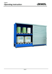
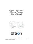
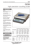
Franke Finland Oy
User’s and
Maintenance manual
Rev. 16.05.2005
Serial number ___________________
DC 2200
2
Table of contents
SAFETY INSTRUCTIONS....................................................................................................................... 3
1.0 GENERAL OF THE DRYING CABINET ............................................................................................ 4
2.0 INSTALLATION INSTRUCTIONS...................................................................................................... 4
3.0 OPERATION INSTRUCTION .............................................................................................................. 5
4.0 PROGRAMS......................................................................................................................................... 7
5.0 PROGRAMMING .................................................................................................................................. 8
6.0 MAINTENANCE................................................................................................................................... 9
6.1 PROGRAMME BUTTON CHECK MODE (ONLY FOR CHECKING).................................................................... 10
6.2. MALFUNCTION INDICATION CODE ER 10.............................................................................................. 10
7.0 TECHNICAL SPECIFICATIONS...................................................................................................... 11
7.1 DIMENSIONAL DRAWING ...................................................................................................................... 11
7.1.2 TECHNICAL DATA ............................................................................................................................. 11
7.2 DIMENSIONAL DRAWING (PASS-THROUGH MODEL)................................................................................ 12
7.2.2 TECHNICAL DATA ............................................................................................................................. 12
7.3 CIRCUIT DIAGRAM ............................................................................................................................... 13
7.3 CIRCUIT DIAGRAM / JAPAN MODELS ..................................................................................................... 14
7.4 SPARE PARTS DRAWING ...................................................................................................................... 15
7.5 SPARE PARTS LIST ............................................................................................................................... 16
8.0 DECLARATION OF CONFORMITY ................................................................................................ 17
9.0 GUARANTEE CONDITIONS ............................................................................................................ 18
3
SAFETY INSTRUCTIONS
WARNINGS
Chamber walls are hot.
The goods and racks are hot to handle.
Be aware of the 230 V voltage.
4
1.0 GENERAL OF THE DRYING CABINET
DC-2200
DC-2200 X
SINGLE DOOR
DOUBLE DOOR (PASS-THROUGH)
The DC-2200 and DC-2200 X drying cabinets are designed especially for drying of
anaesthetic equipment and hoses, surgical instruments, glassware, bowls, dishes,
bottles etc.
The chamber size is dimensioned for 8 shelves. Deko-2000 washer-disinfector´s
shelves fit directly on the rails and any Deko´s spray racks get air blow through their
tubes.
The micro-processor provides the possibility of having a selection of 5 different
programmes suited for various items.
(See point 5.0 Programming).
2.0 INSTALLATION INSTRUCTIONS
1. Installation
Position the drying cabinet. Adjust it vertically and horizontally by adjusting the four
feet.
The flap for outcoming water is in the middle of the bottom of the drying cabinet (for
possible drip water from the goods).
2. Electrical installation
Electrical installation is semi-fixed.
Installation is allowed to be made only by the authorized professional worker in
accordance with the valid directions.
3. Ventilation
Connection to the ventilation system (drawing)
Distance between the outlet and ventilation duct
must be about 100 mm.
Do not connect the ducts together !
The door can be either left or right-handed
- removable lower hinge
- removable axis of hinge
5
3.0 OPERATION INSTRUCTION
CONTROL PANEL
MAIN SWITCH
TEMPERATURE
REMAINING DRYING TIME
PROGRAMME SELECTION BUTTONS
PROGRAMMING BUTTONS
CANCELLATION OF PROGRAMME START WITHIN 5 SECS
CYCLE RUNNING (YELLOW)
Door can be opened during an ongoing drying cycle - heating
will stop.
MALFUNCTION (FLASHING RED SIGNAL)
Turn the main switch to O-position and thereafter back to
position I again. Start a new programme. In case of further
malfunction call for maintenance.
CYCLE COMPLETED (GREEN)
Door must be closed the indicator to come on.
6
HOW TO USE DRYING CABINET
1.
TURN MAIN SWITCH TO POSITION I.
2.
OPEN DOOR AND PLACE GOODS IN.
AN-hose cassettes into the rails at the top in front.
CLOSE DOOR.
3.
SELECT PROGRAM 1-5.
Start program by pushing the program button. Yellow indicator will come on.
PROG indicator shows the remaining drying time. The door can be opened
during a cycle, but heating will be interrupted. By pushing the button + during
the cycle PROG indicator shows the program going on P1 ... P5.
4.
GREEN SIGNAL - PROGRAM COMPLETED, THE DOOR CAN BE
OPENED
Indicator lights up only when the door is closed.
NOTE !
5.
CHAMBER WALLS ARE HOT !
WHEN THE CABINET IS NOT BEING USED PLEASE SWITCH OFF
BY THE MAIN SWITCH.
In pass-through models (with double doors) yellow signal lights at "clean
side" during the cycle. When the cycle ends yellow signal at "clean side"
switches to green and at "unclean side" both yellow and green are lit at the
same time. After opening the door at "clean side" the yellow indicator
switches off and at "unclean side" only the green light is on.
7
4.0 PROGRAMS
Prog.
no
1.
SPECIFICATION
SYMBOL
ADJUSTMENT
RATE
Fan
Temperature
Time
F
C
t
1
85 0C
30 min
2.
Fan
Temperature
Time
F
C
t
1
85 0C
35 min
3.
Fan
Temperature
Time
F
C
t
1
85 0C
40 min
4.
Empty
(can be programmed)
5.
Empty
(can be programmed)
Adjustments
Specification
Fan
Symbol
F
Rate
1
Temperature
C
20 - 90 0C
Time
t
10-99 min
or -- all the time
Note
one speed
8
5.0 PROGRAMMING
F
1.
Press buttons 0 and 3 for 5 sec’s. Release button 3 first and then
button 0. F/I appears on display.
2.
Select the program button to be reprogrammed.
3.
Select fan speed by buttons + and - : 1 (only one speed available),
(if 0 selected, the function of button ignored) Confirm settings by
pressing the button 0.
I
I
F
I
I
C
5
5
I
t
I
0
Temperature selection C.
When selecting the drying temperature (range 20-90 0C) use buttons
+ and -, and confirm by pressing the 0. (See picture; program 1,
55 0C)
Drying time selection t.
When selecting the drying time (range 10-99 min) use buttons
+ and -. Confirm setting by pressing the button 0. (See picture;
program 1, 10 min)
4.
After restoring the last program phase you can start to program
any program button you want.
Press the button 0 to get into operating mode and temperature will
appear on display.
**
Error on the programming procedure:
Switch off the main power and start the programming from the
beginning (or restore the program to be changed by 0 button and
reprogram the button.)
9
6.0 MAINTENANCE
CAUTION !!
NO WATER ALLOWED ON THE TOP OF THE DRYING
CABINET.
1. Daily
Use non-aggressive washing agent and soft wash cloth, for flushing use wet wash
cloth, wipe and dry.
2. Air filter
Cleaning interval in normal use 3 months.
Power connection plug must be disconnected before cleaning or replacing the air
filter. (Turn the main switch to position 0).
Unscrew the safety screw from the separate front plate on the control panel and take
off the air filters (2 pcs) on the rails of the front plate. See the drawing on the page 8.
Wash the air filters with pure water. Use non-aggressive agent when necessary.
Cleaned air filter operates as a new one.
If the air filter is damaged or does not work properly after washing - replace the air
filter with a new one.
When installing the air filters back on to the rails check the direction of the air flow
(arrow pointing downwards). Wet air filter will dry during the drying cycle.
Put the rails into the chamber and tighten the front plate back to the control panel by
the locking screw.
Air filters can be taken
off for cleaning and
replacing
Safety screw
Bottom flap can be opened
for cleaning if necessary
10
6.1 programme button check mode (only for checking)
8
8
8
8
1. Press buttons 0, - and + simultaneously for 5 sec’s. 88/88 appears on
display.
2. Press the program button to be checked. On display you can see
(when button 4 pressed e.g.)
4
4F/1
4
F
1
F
I
= sub display
= button 4 (1-5)
= fan
= speed
Press button +
4
C
6
0
4C/60
4
C
60
appears on display
= button 4
= temperature
= selected temperature (range 20-90 0C)
Press button +
4
t
3
0
8
8
8
8
4t/30
4
t
30
appears on display
= button 4
= drying time
= selected time (range 10-99 min)
Press button + until 88/88 appears. Now you can check the program button
you want. When, for example, 2F/0 appears there is no program restored.
3. After the programe checking you can start operating mode by switching
off and on the main power and the drying cabinet is ready to use.
6.2. Malfunction indication code Er 10
If a fault occurs all the drying cabinet functions will stop and on the digital display
panel will show Er + no. and also a red signal lamp will flash on the panel.
The system can be reset by switching the cabinet mains power switch off and on
again. CALL FOR AN ENGINEER.
Er No
Fault
Reason / Action required
Er10
Overheating protector has gone off
position.
Temperature sensor in the drying
chamber does not function.
Find the reason why this happened
- does the fan rotate
Check the connections; change
temperature sensor
Er4
or
Er5
the
11
7.0 TECHNICAL SPECIFICATIONS
7.1 Dimensional drawing
Electric line 3.5 m
7.1.2 Technical data
1.
Voltage
230 V/400 V, 3-phase, 50 Hz
Power rating 5,6 kW (heating 5,2 kW)
Fuses
16 A
2.
Voltage
230 V, single phase, 50 Hz
Power rating 3,6 kW (heating 3,3 kW)
Fuses
16 A
3.
Voltage
200 V, 3-phase, 60 Hz Japan
Power rating 4 kW
Fuses
20 A
Common for all:
Exhaust air
Number of hoses
Weight
100 m3/h
12 pcs
165 kg
12
7.2 Dimensional drawing (pass-through model)
Electric line 3.5 m
7.2.2 Technical data
1.
Voltage
230 V/400 V, 3-phase, 50 Hz
Power rating 5,6 kW (heating 4,8 kW)
Fuses
16 A
2.
Voltage
230 V, single phase, 50 Hz
Power rating 3,6 kW (heating 3,3 kW)
Fuses
16 A
3.
Voltage
200 V, 3-phase, 60 Hz Japan
Power rating 4 kW
Fuses
20 A
Common for all:
Exhaust air
Number of hoses
Weight
100 m3/h
12 pcs
165 kg
13
7.3 Circuit diagram
L1-3
MS
T1
Fan
K
OT
HE
Phase advance
Main switch
C1
Transformer 12 V
F1
Ventilator
Capacitor 6µF,400V F2
Overheating protector
Heating elements
2x2400 W
Contactor
Fuse 125 mA (T)
Fuse 2A (F)
Output
1. Ventilator power 1
5. Heating contactor
20. Yellow in operation indicator by clean side
(pass-through model)
21. Green cycle completed indicator by clean
side (pass-through model)
24. 12VDC minus terminal
Input
5. Common for all incoming
6. Front door
7. Back door (pass-through model)
15. Pass-through model identifier
16. Thermal sensor in chamber
17. Thermal sensor in chamber
14
7.3 Circuit diagram / Japan models
L1-3
MS
T1
Fan
K
OT
HE
Phase advance
Main switch
C1
Transformer 12 V
F1
Ventilator
Capacitor 6µF,400V F2
Overheating protector
Heating elements
2x2000 W
Contactor
Fuse 315 mA (T)
Fuse 4 A (F) (2 pcs)
Output
1. Ventilator power 1
5. Heating contactor
20. Yellow in operation indicator by clean side
(pass-through model)
21. Green cycle completed indicator by clean
side (pass-through model)
24. 12VDC minus terminal
Input
5. Common for all incoming
6. Front door
7. Back door (pass-through model)
15. Pass-through model identifier
16. Thermal sensor in chamber
17. Thermal sensor in chamber
15
7.4 Spare Parts Drawing
ELECTRICS
16
7.5 Spare Parts List
No.
Code
1.
2.
3.
4.
5.
N23664A
N23546
N22715A
N23485
N22763
6.
7.
8.
9.
10.
11.
12.
14.
16.
17.
18.
19.
21.
22.
23.
24.
Description
Lock
Silicon sealing
Fan G2E 160-AD01-21, 230 VAC
Air filter, 2 pcs
Heating element 220 V 1630/750 W, 2 pcs
Heating element 200 V 2 x 2000 W
N22467
Microswitch 1066776
N22514
Main switch 16A PR12
N22415A Process card
N22844
Flat cable 70 cm
N22416A Relay card
N22680
Transformer 230 V/12 V 0.5A/12 V 0.5A
N22618A Contactor
N22712
Overheating trip 16 A/250 V T150, 2 pcs
(automatic reset when switched off)
N28009
Filter
N22670
Fuse 5x20 2A (F)
N22671
Fuse 5x20 4A (F) (2 pcs)
N23703
Fuse 5x20 125 mA (T)
N22646
Fuse 5x20 315 mA (T)
N22710
Temperature sensor PTC 90o
N23327
Adjustable foot M24, 4 pcs
N22614
Signal lamp 12 V
N22801
Lens, green
N22800
Lens, orange
NOTE
only in Japan
only in Japan
only in Japan
Double door models
-“-“-
17
8.0 DECLARATION OF CONFORMITY
Manufacturer:
FRANKE FINLAND OY
Address:
Vartiokuja 1, 76850 Naarajärvi, FINLAND
Hereby declares that:
DC-2200
complies with the following Directives:
- Machinery Directive
- Low voltage Directive
- EMC Directive
(89/392/EEC, 91/368/EEC, 93/44/EEC)
(73/23/EEC)
(89/336/EEC, 92/31/EEC)
and that the following harmonized standards have been applied:
- EN 50081-1
Electromagnetic compatibility. Generic emission standard
- EN 50082-1
Electromagnetic compatibility. Generic immunity standard
(Signature)
Antero Asikainen, Managing Director
18
9.0 GUARANTEE CONDITIONS
Dear Deko Customer,
The Deko machines are manufactured with great care, prior to delivery they must pass
an extensive quality control. If your machine shows any material or manufacturing defect,
you will have a legitimate claim against the company from which you bought your Deko
machine.
In addition, we assume the warranty for new machines as follows:
1.
Within the warranty period we shall repair any faults with your Deko machine, free of
charge, if caused by a material or manufacturing defect. Replaced defective parts
will be returned to us.
2.
Should a defect occur in your Deko machines standard accessories (delivery)
included within the warranty period of 12 months max. 18 months from
manufacturing date, please inform the company from which your bought your
machine, or the responsible Deko sales branch.
3.
The warranty period starts with the delivery of the new Deko machine to the
end user.
Observance of the warranty period is established by presentation of the fulfilled
warranty card.
4.
Faulty machines are repaired free of charge at our discretion. Replaced parts will
become our property.
5.
Repair work at the installation location, within the 12 months from the date of
delivery we shall carry out the warranty work without charging for transport and travel
costs. At a later date, these will have to be reimbursed.
6.
A warranty claim is not valid for defects caused by tampering or repair work carried
out by unauthorized persons. This also applies to the fitting of additional
accessories, which were not designed for our machines.
7.
If a machine, which has been repaired within the warranty period, develops the same
fault within 3 months after the repair, the fault will be repaired free of charge, if the
cause for this defect is inexpert repair work, or a material or manufacturing defect of
the replaced spare parts, or of the replaced machine. Otherwise the warranty period
will not be extended by warranty work.
8.
Additional or different claims, especially those for damages caused outside the
machine are invalid, unless a liability is enforced by law.
If you call, we require the following information from you:
- type of machine and its serial number
- date of purchase ( see invoice/receipt )
- type of defect / description
- your complete address
- time when you can be contacted
19
Franke Finland Oy
Guarantee certificate
Model:
Serial number:
Installed & commissioned:
The guarantee is valid for 1 year after installation and commissioning.
Installer:
Inspections:
Inspector / Date
Leakage test
Test drive
Electrical test
Washing pressure test
General inspection
This product complies with the Medical Device Directive
This product is equipped with CE-mark
Franke Finland Oy
Naarajärvi Factory
76850 Naarajärvi
FINLAND
Phone
Fax
+358 15 34 111
+358 15 3411 560