1
-J02821
REV. 2003-04-14
SISSY BAR SIDE PLATE KIT
NOTE
Prior to performing the following step, obtain a little slack for
the turn signal assembly by reaching under the fender and
bending open the aluminum tab on the clip securing wiring to
fender.
GENERAL
Kit Number
53925-04
Models
3.
Remove the locknut (B) from the turn signal stud (E) and
gently remove the turn signal assembly from fender support cover, fender support and fender. Save locknut for
installation. The turn signal will remain loosely attached
to motorcycle by rear directional wire.
The rider's safety depends upon the correct installation
of this kit. Use the appropriate service manual procedures.
If the procedure is not within your capabilities or you do
not have the correct tools, have a Harley-Davidson dealer
perform the installation. Improper installation of this kit
could result in death or serious injury. (00333a)
4.
Carefully position the side plate between fender support
and fender. While holding sideplate in position, line up the
screw mounting holes and make sure the turn signal wiring
passes through the cutout (slot) in the side plate. Coat
threads of screws (1 and 2) from kit with Loctite 243 (blue)
(Harley-Davidson part number 99642-97) and install
locknut and clipnut, however do not tighten completely.
NOTE
5.
Add Loctite 243 (blue) (Harley-Davidson part number
99642-97) to turn signal stud and install through fender
support cover, fender support, side plate and fender. Install
locknut and tighten to 8-13 ft-lbs (11-18 Nm). Making sure
sideplate remains aligned, return to fender support screws
and tighten to 8-13 ft-lbs (11-18 Nm).
6.
Reach under fender and position turn signal wiring into
tab on clipnut.
7.
Obtain reflector (3) from kit. Peel off protective strip
backing and firmly press reflector (3) to side plate (4),
centering reflector horizontally and vertically.
Repeat steps 1 through 7 on opposite side of fender.
This kit is designed for installation on all 2004 and Later XL
Sportster® model motorcycles.
This instruction sheet references Service Manual information.
A Service Manual for your model motorcycle is required for
this installation and is available from a Harley-Davidson Dealer.
Kit Contents
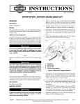
See Figure 1 and Table 1.
INSTALLATION
NOTE
When removing rear fender reflectors, be careful not to damage
fender paint.
1.
Carefully remove the rear reflector. Remove any remaining
adhesive from the back side of the reflector and any
adhesive from the side of the fender.
8.
2.
See Service Parts Illustration. Remove the screws,
washers, locknuts and clipnuts that attach the fender
support cover and fender support to fender. Discard the
button head screws but retain the washers (A), locknuts
(B,C) and clipnuts (D) for installation.
Federal Motor Vehicle Safety Standard (FMVSS) 108
requires motorcycles to be equipped with rear and side
reflectors. Be sure rear and side reflectors are properly
mounted. Poor visibility of rider to other motorists can
result in death or serious injury. (00336b)
SERVICE PARTS
See Figure 1 and Table 1.
-J02821
Many Harley-Davidson® Parts & Accessories are made of plastics and metals which can be recycled.
Please dispose of materials responsibly.
1 of 2
is01081
4
3
D
B
C
A
2
E
A
1
Figure 1. Service Parts: Sissy Bar Side Plate Kit
Table 1. Service Parts Table
Item
Description (Quantity)
Part Number
1
Screw, TORX 1-3/4 inch (2)
4783
2
Screw, TORX 1-3/8 inch (2)
4187
3
Reflector, framed red (2)
59259-90
4
Side plate, rigid (right side)
53927-04
5
Side plate, rigid (left side), (not shown)
53926-04
Items mentioned in text, but not included in kit:
A
Washer
B
Locknut
C
Locknut
D
Clipnut
E
Turn signal stud
-J02821
2 of 2