1
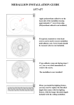
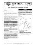
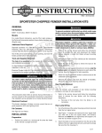
-J03063
REV. 2006-06-20
SISSY BAR MOUNTED AUXILIARY BRAKE AND TAIL LIGHT
GENERAL
is01457
Kit Number
1
Kit Number 59429-04, Light Kit with Red Lens
Kit Number 59470-06, Light Kit with Smoked Lens
Models
2
These kits fit 1999 and later XL models, 1996 and later Dyna™
and 1996 and later Softail models (except 2006 FXSTC)
equipped with a Medallion Plate-Style Sissy Bar Upright. Will
not fit with Backrest Pads that have mounting brackets that
match the contour of the sissy bar medallion. Will not fit with
sissy bar mounted storage bags.
Additional Parts Required
See Figure 2. To provide clearance for the auxiliary brake and
tail light, backrest pads with mounting holes (5) spaced 2.55
inch (64.8 mm) center to center require the purchase of a
Backrest Mounting Bracket Kit (Part No. 59545-04). This
mounting bracket replaces the existing backrest mounting
bracket (3).
1. Adhesive mounted medallion
2. Push nut mounted medallion
Figure 1. Medallions
is01458
The rider's safety depends upon the correct installation
of this kit. Use the appropriate service manual procedures.
If the procedure is not within your capabilities or you do
not have the correct tools, have a Harley-Davidson dealer
perform the installation. Improper installation of this kit
could result in death or serious injury. (00333a)
4
5
NOTE
1
This instruction sheet references Service Manual information.
A Service Manual for your model motorcycle is required for
this installation and is available from a Harley-Davidson Dealer.
INSTALLATION
1.
Follow the instructions in the Service Manual to remove
the seat.
3
2
To prevent accidental vehicle start-up, which could cause
death or serious injury, disconnect negative (-) battery
cable before proceeding. (00048a)
Disconnect negative (-) battery cable first. If positive (+)
cable should contact ground with negative (-) cable connected, the resulting sparks can cause a battery explosion,
which could result in death or serious injury. (00049a)
2.
1.
2.
3.
4.
5.
Screw
Screw (2)
Backrest bracket
Backrest pad
Mounting hole spacing (center to center)
Figure 2. Backrest Pad and Bracket
Disconnect battery cables, negative (-) cable first.
-J03063
1 of 5
Remove the Backrest Pad
is01459
NOTE
4
Medallions are attached to a medallion plate between the
uprights of the sissy bar using either adhesive or push nuts.
1.
See Figure 1. Remove and retain any existing medallion.
Adhesive Mounted Medallion (1): Carefully pry the
medallion (1) from the plate. Remove any adhesive residue
from the back of the medallion and the sissy bar medallion
plate. To avoid contaminating the adhesive backing, place
the medallion in an area away from dirt and debris.
2
3
Push Nut Mounted Medallion (2): Carefully pry the edge
of the medallion until the medallion is free of the push nuts.
2.
See Figure 2. Remove and retain the screw (1) that
secures the backrest pad to the plate.
3.
Remove and retain the two screws (2), backrest bracket
(3) and backrest pad (4).
5
1
Install the Light Assembly
1.
See Figure 3. Clean the front of the medallion plate (2)
with a 50/50 solution of isopropyl alcohol and water.
2.
Peel the adhesive backing from the adhesive tape located
on the light assembly (1). Fit and hold the light assembly
to the front of the medallion plate (2).
3.
See Figure 6. For 2.55 inch (64.8 mm) center to center
mounting hole backrest pads, use the bracket kit (Part
Number 59545-04) and sandwich the light assembly
between the bracket frame and the medallion plate. The
bracket clamps will fit around the back of the sissy bar
arms.
4.
5.
6.
Light assembly
Medallion plate
Spacer
Backrest pad
Screw
Figure 3. Light Assembly, Spacer and Backrest Pad
is01460
See Figure 3. Place the spacer (3) in the center hole in
the light assembly, and place the backrest pad (4) against
the light assembly/sissy bar. Install the screw (5) through
the medallion plate and spacer, to secure the backrest
pad.
1
See Figure 4. Secure the harness (2) to the sissy bar
upright, using either adhesive-backed metal clips or cable
straps at locations (1) near the light assembly and the side
plate. If using adhesive-backed metal clips, snap the light
assembly harness (2) into the clips.
3
4
Hold light assembly harness (2) against a sissy bar upright,
and install the backrest bracket (3) using two screws
included in the kit.
NOTE
To ensure maximum adhesion, clean the area of the frame
where the adhesive clips are to be placed using a 50/50 solution of isopropyl alcohol.
7.
1.
2.
3.
4.
5.
Softail and Dyna and 1999 to 2003 XL models: Route
the light assembly wiring harness along the fender support.
Secure the harness to the fender support using adhesivebacked metal clips.
2
1.
2.
3.
4.
Adhesive clip/cable strap locations (2)
Light assembly harness
Backrest bracket
Screw (2)
Figure 4. Install the Backrest Bracket
2004 and later XL models: See Figure 5. Route the light
assembly wiring harness (2) along the fender support and
along the inside of the frame tube. Secure the wiring harness using adhesive-backed plastic clips (1) placed as
shown.
-J03063
2 of 5
is01461
is01462
2
1
1. Adhesive backed clips
2. Wiring harness
Figure 5. Harness Routing - XL Models
Connect the Light Assembly
1.
Locate and separate the taillamp wiring harness connector
[7B] from the main harness taillamp connector [7A].
2.
Following the instructions in the Service Manual, note the
cavity numbers and remove the main harness black, blue
and red/yellow leads (with pin terminals) from the taillamp
connector [7A].
3.
See Figure 7. Install the main harness leads removed from
the taillamp connector [7A] into the 3-way pin housing (1)
provided in the kit as follows:
a.
The blue lead (2) to cavity 1.
b.
The red/yellow lead (3) to cavity 2.
c.
The black lead (4) to cavity 3.
4.
Mate the kit 3-way connector (1) to the socket housing (5)
on the Y-harness (6) from the kit.
5.
Mate the 3-way connector (10) on the Y-harness to the
sissy bar mounted auxiliary brake and tail light assembly
wire connector.
6.
Install the blue, red/yellow and black terminated leads (7,
8 and 9) from the Y-harness into the numbered cavities
of the taillamp connector [7A] that matched the original
main harness lead colors.
7.
Mate the main harness connector [7A] to taillamp wiring
harness socket connector [7B].
-J03063
Figure 6. Bracket for 2.55 inch (64.8mm) Pad Hole Spacing
(light assembly installed - view from front of sissy bar)
3 of 5
Return Motorcycle to Service
is01463
7
8
9
10
Connect positive (+) battery cable first. If positive (+) cable
should contact ground with negative (-) cable connected,
the resulting sparks can cause a battery explosion, which
could result in death or serious injury. (00068a)
1.
Connect the battery cables, positive (+) cable first.
After installing seat, pull upward on seat to be sure it is
locked in position. While riding, a loose seat can shift
causing loss of control, which could result in death or
serious injury. (00070b)
2.
Follow the instructions in the Service Manual to install the
seat.
6
5
If ABS lamp remains on continuously, the ABS is not
operating. The standard brake system is operational, but
wheel lock up can occur. Contact a Harley-Davidson Dealer
to have ABS repaired. A locked wheel will skid and can
cause loss of vehicle control, which could result in death
or serious injury. (00361a)
1
3.
Turn ignition on and test for proper brake light and tail light
operation.
4.
Install the medallion.
Adhesive Mounted Medallions: Center the medallion on
the plate, and press the medallion firmly onto the plate.
4
2
3
1. 3-way pin housing (mates to Y-harness socket
housing)
2. Blue lead (from main harness)
3. Red/yellow lead (from main harness)
4. Black lead (from main harness)
5. Socket housing
6. Y-harness
7. Blue lead (to tail lamp connector [7A])
8. Red/yellow lead (to tail lamp connector [7A])
9. Black lead (to tail lamp connector [7A])
10. 3-way socket housing (mates with light assembly
connector)
Push Nut Mounted Medallions: Align the pins on the
medallion (2) with the "push nuts" on the medallion plate,
and push the medallion firmly into the "push nuts."
SERVICE PARTS
See Figure 8 and Table 1.
Figure 7. Y-Harness Wiring Diagram
-J03063
4 of 5
is01464
1
3
6
2
5
8
4
11
10
9
7
9
8
10
11
Figure 8. Service Parts: Sissy Bar Mounted Auxiliary Brake and Tail Light
Table 1. Service Parts Table
Item
Description (Quantity)
Part Number
1
Clip, adhesive-backed metal (4)
10102
2
Clip, adhesive-backed plastic (2)
10120
3
Cable strap (6)
10006
4
Spacer
Not sold separately
5
Y-harness (includes 3-way pin housing)
70327-04
6
Light assembly, hi-mount sissy bar
Not sold separately
7
Backrest mounting bracket kit
59545-04
8
Connector housing
73153-96BK
9
Socket terminals (3)
73191-96
10 Connector housing
73103-96BK
11 Pin terminal
73190-96
-J03063
5 of 5