1
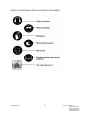
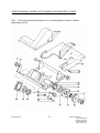
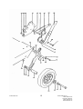
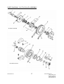
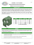
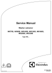
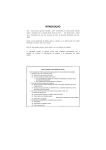
OPERATOR'S SPARE PARTS & SERVICE MANUAL Plate Compactor Models PP193 & PD193 FAIRPORT CONSTRUCTION EQUIPMENT LTD Blagden Street Sheffield S2 5QS ENGLAND Tel: +44 (0) 114 276 7921 Fax: +44 (0) 114 272 0965 Email: [email protected] Website: www.fairport.uk.com M-PP193ws.doc Unit 32, The Bell Centre, Newton Road, Manor Royal, Crawley, West Sussex, RH10 9FZ Tell +44 (0) 1293 534742 Fax +44 (0) 1293 529056 Issue 3226-Sep 01 CONTENTS 1. SAFETY PRECAUTIONS 2 SAFETY PICTOGRAMS USED ON FAIRPORT EQUIPMENT 3 2. TECHNICAL DATA 4 3. STARTING THE ENGINE 5 4. OPERATOR INSTRUCTIONS 5 5. GENERAL MAINTENANCE 6 6. ENGINE 6 7. VEE BELT ADJUSTMENT 6 8. CENTRIFUGAL CLUTCH 6 8.1. M TYPE CLUTCH 6 8.2. B TYPE CLUTCH 7 9. ENGINE MOUNTING PLATE AND ANTI-VIBRATION MOUNTS 8 10. HANDLE, BRACKETS AND ANTI-VIBRATION MOUNTS 8 11. WHEEL ARM ASSEMBLY 8 12. VIBRATOR UNIT 8 13. BLOCK COMPACTING ATTACHMENT PLATE 9 14. PARTS LIST - BASE PLATE, ENGINE PLATE, BELT GUARD AND ENGINES 12 15. PARTS LIST WHEEL ARM AND HANDLE BRACKET 16 16. PARTS LIST CLUTCH PULLEY ASSEMBLY 18 16.1. M TYPE CLUTCH 18 16.2. B TYPE CLUTCH 18 17. PARTS LIST BLOCK COMPACTING ATTACHMENT PLATES 19 18. WATER SPRINKLER KIT 19 19. WARRANTY CONDITIONS AND CLAIMS PROCEDURE 20 CONDITIONS 20 CLAIMS PROCEDURE 21 20. REPAIRS AND ESTIMATES 21 M-PP193ws.doc 1 Issue 3226-Sep 01 Issue 3285 Oct 02 Issue 3415 Sept o4 Issue 3436 Jan 05 Issue 3523 Dec 05 1. SAFETY PRECAUTIONS Do not operate this machine unless all guards are in position and secure. Do not smoke when refuelling. Do not refuel with engine running. Wipe up spilt fuel. Do not overfill. Dispose of fuel contaminated wipes safely. Do not run engine in enclosed areas without adequate ventilation. Do not run engine in an area that has a hazardous or explosive atmosphere. Disconnect H.T. lead from spark plug on petrol engines before carrying out any maintenance. Turn off fuel when not using machine. Wear protective footwear, ear defenders and gloves. Comply with site safety regulations. Check condition of anti-vibration mounts between engine plate and base plate before lifting. M-PP193ws.doc 2 Issue 3226-Sep 01 Issue 3285 Oct 02 Issue 3415 Sept o4 Issue 3436 Jan 05 Issue 3523 Dec 05 SAFETY PICTOGRAMS USED ON FAIRPORT EQUIPMENT M-PP193ws.doc 3 Issue 3226-Sep 01 Issue 3285 Oct 02 Issue 3415 Sept o4 Issue 3436 Jan 05 Issue 3523 Dec 05 2. TECHNICAL DATA Engines Type Net BHP at operating speed Operating speed 4.7 3.7 4.0 3.6 3300 RPM 3300 RPM 3300 RPM 3300 RPM Honda GX160 Robin EY20 B&S 5HP Yanmar L40AE Dimensions Base plate width: Overall length Width, wheels down: Height, wheels up: 460mm 960mm 600mm 870mm Weight with Honda GX160: Robin EY20: B&S 5HP: Yanmar L40AE: 92.0 kg 92.0kg 93.3kg 103.0kg Noise Levels Honda GX 160 Guaranteed Sound power level: Sound pressure level at Operators Ear: 108. dB Lwa 98 db Lpa Test condition: To BS 500-4 2001 Hand/Arm Vibration (maximum axis) 13.8m/Sec2 Honda GX160 Test condition: To BS 500-4 2001 Performance Vibration frequency 5500 V.P.M. Centrifugal force 1570 kg M-PP193ws.doc 4 Issue 3226-Sep 01 Issue 3285 Oct 02 Issue 3415 Sept o4 Issue 3436 Jan 05 Issue 3523 Dec 05 3. STARTING THE ENGINE Check oil level. Turn fuel tap on. Put speed control lever to tick-over. If engine is cold, close the choke (petrol engines only). Turn engine switch to ON(1) position. Pull the starter rope toggle lightly until resistance is felt, then pull briskly using quick short pull. Do not pull rope to its full extent or allow toggle to snap back against engine. Return it gently to avoid damage. When engine is warm open choke. Position engine speed control lever to give required engine speed (usually full speed). Commence vibration - the compactor is self-travelling. To stop engine, position the engine speed control to slow and turn the engine switch to off(0). Turn the fuel valve to off. 4. OPERATOR INSTRUCTIONS Read section (1) - Safety. NOTE: Drive between engine and vibrator is through a centrifugal clutch. Vibration will commence as engine speed is increased. Position the engine speed control lever to give required speed (usually full speed). Commence compaction. The compactor is self travelling. Its speed of travel and the number of passes required to achieve optimum compaction depends on the type and condition of material being compacted and the layer depth. Uniformly graded granular material compacts far more efficiently than wet cohesive material. When compacting block paving always use a rubber attachment mat, contact your agent for details. When compacting blacktop always use a water spray, contact your agent for details. M-PP193ws.doc Issue 3226-Sep 01 5 Issue 3285 Oct 02 Issue 3415 Sept o4 Issue 3436 Jan 05 Issue 3523 Dec 05 Do not run the machine on solid concrete surfaces, as this is likely to cause damage. 5. GENERAL MAINTENANCE Top up engine oil daily and change regularly using the correct grade of oil in accordance with the engine manufacturers instructions. If the machine is working continuously, check the oil level and top up twice daily. Clean the air filter element regularly. In very dry, dusty conditions, this should be done daily. Lightly oil the wheel spindles and wheel arm spindles monthly. Check tightness of all nuts and bolts monthly. 6. ENGINE Removal Unfasten screws (19) and remove the guard (20) and the vee belt (16). Remove the engine mounting bolts (21) and nuts and lift off engine. For engine service, refer to the manufacturer’s instructions. Replacement To refit engine, reverse removal instructions. Set engine speed to 3300 r.p.m. 7. VEE BELT ADJUSTMENT Unfasten screws (19), remove the guard and check belt tension. It is important to note that belt tension in this application is much less than is generally accepted as normal. Too high a belt tension may lead to engine damage due to excessive transmission of vibration from the power pack through the vee belt. To adjust belt tension, loosen the engine mounting nuts and screws (21) and move the engine backwards towards the handle until the front of the engine mounting plate moves downwards slightly. Adjust the engine position to allow the mounting plate to just return to normal level position and tighten the engine mounting nuts and screws after making a final check that the clutch pulley is in line with the bottom pulley. 8. CENTRIFUGAL CLUTCH 8.1. M TYPE CLUTCH Removal Remove the guard and vee belt. M-PP193ws.doc 6 Issue 3226-Sep 01 Issue 3285 Oct 02 Issue 3415 Sept o4 Issue 3436 Jan 05 Issue 3523 Dec 05 Remove the four bolts (15) and nuts which hold the clutch assembly together. Warm the front cover bearing housing (14) and tap the back of the vee belt pulley to withdraw the pulley and front cover. The clutch shoes and inside face of the pulley can now be inspected. If no further work is required, reassemble in reverse order. To further dismantle remove the outer bearing (6) and spacer (13) using a suitable extractor. To remove the clutch, release the locking tab from the taper lock nut (17) and remove the nut and lock washer. Use a suitable extractor to pull the clutch off the taper lock sleeve. If both the clutch and taper lock sleeve move together, continue to pull until they have moved about 3mm along the shaft adaptor. Now remove pulley extractor and screw on taper lock nut for about 3 turns. Place a short length of tube over the end of the shaft so that the end of the tube bears against the taper lock nut. Give the tube a sharp tap with a hammer to release the taper lock. The taper lock and clutch can now be easily withdrawn. Lever out key (1), unscrew the countersunk screw (4) and withdraw the shaft adaptor. If the shaft adaptor is screwed onto a threaded shaft, grip the large diameter with "Mole" grips and unscrew (right hand thread). Replacement Re-assemble in reverse order. To position the pulley assembly and clutch correctly, fit the distance ring (7) against the shoulder on the shaft adaptor with the recessed side facing outwards. The taper sleeve butts up against the distance ring. 8.2. B TYPE CLUTCH Removal To remove the clutch from an engine with a 3/4" keywayed shaft unscrew screw (33), withdraw spacer (29) and pull clutch assembly off shaft. To remove clutch from an engine with a 5/8" unf shaft unscrew nut (34), remove washer (35) and withdraw clutch assembly. It is possible that when nut (34) is unscrewed shaft adaptor (37) will unscrew from the engine shaft rather than the nut unscrewing from the adaptor. If this happens remove entire assembly, grip the shoulder end of the adaptor in a vice suitably supported internally with a short length of 5/8" bar inserted into the end of the adaptor and unscrew nut (34) as above. To dismantle the clutch remove circlips (27) and (28) and press out hub(24) complete with shoes and springs. If it is necessary to remove the shoes and springs note first the orientation of the shoes in the hub and which notch is located on the hub. Care also should be taken when removing the springs. M-PP193ws.doc 7 Issue 3226-Sep 01 Issue 3285 Oct 02 Issue 3415 Sept o4 Issue 3436 Jan 05 Issue 3523 Dec 05 Replacement Replacement is the reverse of the above procedure but ensure the shoes are replaced to the same orientation as the ones removed. 9. ENGINE MOUNTING PLATE AND ANTI-VIBRATION MOUNTS Removal Unscrew screws (27) and lift off the engine plate. The anti-vibration mounts can now be removed after unscrewing nuts (63). Replacement Inspect anti-vibration mounts for deterioration, cracking, tearing etc. and renew if necessary. Refit anti-vibration mounts to brackets on base plate ensuring a star washer is between the mount and the bracket and that there is also one under the nut. Do not tighten the nuts at this stage. Refit engine base plate fully tightening screws (27) remembering to place star washers under head of screws. If a mount tends to twist when screw (27) is tightened, ensure nut (63) is loose. Finally, tighten nuts (63). 10. HANDLE, BRACKETS AND ANTI-VIBRATION MOUNTS To remove handle, unscrew special screws (47). The handle can now be lifted clear. When re-fitting the handle, ensure that star washers are placed between the handle and the anti-vibration mount to prevent the mount from twisting when the special screws (47) are tightened. Dismantling of the brackets is straight forward, but take care not to over tighten the locking lever bolt (43) when reassembling. 11. WHEEL ARM ASSEMBLY Dismantling and reassembly of the wheel arm is straightforward. However, prior to reassembly it is worthwhile applying a thin coating of graphite grease to the wheel arm pivot and to the wheel axle. It should be noted that the dished side of disc spring (48) faces the wheel arm. 12. VIBRATOR UNIT M-PP193ws.doc 8 Issue 3226-Sep 01 Issue 3285 Oct 02 Issue 3415 Sept o4 Issue 3436 Jan 05 Issue 3523 Dec 05 Dismantling Remove brackets (38). To remove the pulley (32) release the locking tab of the taper lock nut (31) and unscrew the locknut approximately two turns. Place supporting wedges between the pulley and the vibrator case end plate (30). Position a short length of tube over the end of the shaft so that it bears against the taperlock nut. Give the tube a sharp tap with a hammer to release the taper lock and remove pulley and taper lock from shaft. Unscrew the cap head screws retaining the end plate and remove the end plates. If it is felt that the bearings are not worn, but need regreasing, use Castrol BM2 or an equivalent grease. Half fill the bearings and fully fill the end caps. If the bearings are to be renewed, continue dismantling as follows. Strike the long end of the vibrator spindle with a copper faced mallet. This will drive out the vibrator spindle and far bearing. Remove the near bearing by striking it with a suitable drift inserted from the far end. Reassembly Grease the bearings as described above First place a bearing shield (64) over the short end of the vibrator spindle with grooved side facing outwards and then press on a bearing. Apply a thin layer of grease to the outside of the bearing and to the bearing housing. Offer the bearing, spindle and bearing shield to the housing and force home using copper faced mallet or press. Fasten the rear cover (36) into position using cap head screws (33) Place a bearing shield over the end of the shaft. Lightly grease the inner and outer surfaces of the second bearing and also the shaft and housing. Force the bearing onto the shaft and into the housing using a suitable tubular drift and copper faced mallet. Renew the seal in the end plate and refit end plate. NOTE: Some older base plates might not have a shoulder in the bearing housing. For these applications only Nilos ring, Part No. W81053 may be used. These fit on the shaft between shoulder and bearing. If they are not available, pre lubricated bearings; Part No. W81020 with shields may be fitted. For housings that do have a shoulder, bearing shield, Part No. W51788 should be used. Replace the bottom pulley and taper lock, but do not tighten until the engine is in position and pulley adjustment can be checked. 13. BLOCK COMPACTING ATTACHMENT PLATE For Fabricated Base Plate M-PP193ws.doc 9 Issue 3226-Sep 01 Issue 3285 Oct 02 Issue 3415 Sept o4 Issue 3436 Jan 05 Issue 3523 Dec 05 On some base plates it will be necessary to mark out and drill the fixing holes. It is recommended that the base plate is removed to make this easier. Place the base plate the right way up onto the edge of the attachment plate abutting one of the studs and with the sloping face of the base plate nesting in the sloping face of the attachment plate. Mark the edge of the base plate where the front holes and studs in the attachment plate come and use these marks to scribe underneath the base plate the transverse centre lines of the holes to be drilled. Mark the front to back centre line. Drill three 11mm diameter holes through the front sloping face, one on the centre line and 205mm each side of the centre line and drill two 11mm diameter holes 115mm each side of the centre line for the studs. Refit the base plate. Fit the attachment plate with the fastenings provided. Check tightness of fastenings after 15 minutes operation. For Cast Base Plate Place the compactor on the attachment plate and check that the holes in the attachment plate line up with the slots in the base plate. Fasten attachment to base plate with screws and washers provided. The large diameter washers with a flat are fitted on the inside of the front and the fully rounded large diameter washers are fitted at the rear. Check tightness of fastenings after 15 minutes operation. M-PP193ws.doc 10 Issue 3226-Sep 01 Issue 3285 Oct 02 Issue 3415 Sept o4 Issue 3436 Jan 05 Issue 3523 Dec 05 PARTS DIAGRAM - BASE PLATE, ENGINE PLATE AND BELT GUARD N.B. To prevent torsional distortion of A-V mounts tighten screws 27 before tightening nuts 63. M-PP193ws.doc 11 Issue 3226-Sep 01 Issue 3285 Oct 02 Issue 3415 Sept o4 Issue 3436 Jan 05 Issue 3523 Dec 05 14. PARTS LIST - BASE PLATE, ENGINE PLATE, BELT GUARD AND ENGINES Item No. Part No. Description Qty 19 20a 20b 21 22 23 24 25a 25b 26 27 28 29 29 30 31 32a 32b 33 34 35 36 37 435/8/16 W51819 W51765 435/8/40 420/8/25 W526/8 480/8 W51811 W51772 439/10 469/10/16 W51809 W81054 W81020 W50243 W80098 W51810 W55036 455/6/22 435/10/30 480/10 W50240 W80466 W88909 W51812 W51808 439/8 480/10 W51788 W81053 W81246 M8 x 16 Hex. hd. bolt Belt guard (petrol engines) Belt guard (Yanmar engine) M8 x 40 hex. hd. eng. mt. bolt M8 Washer M8 large. dia. washer M8 Nyloc nut Engine plate (petrol engines) Engine plate (Yanmar L40 engine) M10 Star washer M10 x 16 Csk. Skt. Screw Eccentric weight and shaft Ball bearing (for use with ring item 64) Ball bearing (with out ring item 64 ) Front cover Taper sleeve Lower pulley for use with M type clutch Lower pulley for use with B type clutch M6 x 22 cap. hd. screw M10 x 30 hex. hd. bolt M10 Nyloc nut Rear cover A.V. mount A.V. mount after Oct 2002 Front bracket Base plate M8 star washer M10 nut Bearing shield (for shouldered brg hsg) Nilos ring (for straight through brg. hsg) Lip seal 5 1 1 3 3 3 13 1 1 28 4 1 2 2 1 1 1 1 8 4 4 1 4 4 2 1 7 4 2 2 1 38 39 51 63 64 64 65 Additional requirements for diesel version (not illustrated) W51773 W51774 Rear buffer bracket Rear buffer 2 2 Engine Part Numbers Honda GX160 screwed shaft Honda GX160 keywayed shaft Robin EY20 screwed shaft Robin EY20 keywayed shaft M-PP193ws.doc W81732 W81731 W81798 W81776 12 Issue 3226-Sep 01 Issue 3285 Oct 02 Issue 3415 Sept o4 Issue 3436 Jan 05 Issue 3523 Dec 05 Briggs & Stratton keywayed shaft Yanmar L40 keywayed shaft M-PP193ws.doc W81924 W81843 13 Issue 3226-Sep 01 Issue 3285 Oct 02 Issue 3415 Sept o4 Issue 3436 Jan 05 Issue 3523 Dec 05 PARTS DIAGRAM - WHEEL ARM AND HANDLE BRACKET M-PP193ws.doc 14 Issue 3226-Sep 01 Issue 3285 Oct 02 Issue 3415 Sept o4 Issue 3436 Jan 05 Issue 3523 Dec 05 M-PP193ws.doc 15 Issue 3226-Sep 01 Issue 3285 Oct 02 Issue 3415 Sept o4 Issue 3436 Jan 05 Issue 3523 Dec 05 Items Fitted to Engines (not illustrated) W51784 433/6 437/6/16 418/6 480/6 W81805 W81846 W81860 15. Throttle stop (for Honda engines) Ext. star washer (for throttle stop) M6 x 16 screw " M6 washer " M6 nyloc nut " Exhaust deflector (for Honda engine) Deflector screws " Exhaust deflector (for B & S.engine) 1 1 1 1 1 1 2 1 PARTS LIST WHEEL ARM AND HANDLE BRACKET Item No. Part No. Description Qty 24 25 26 40 41 41 42 43 44 45 46 47 48 50 51 52 54 55 67 68 69 70 71 72 73 74 75 76 480/8 W51811 439/10 437/8/20 W51814 W51815 W80467 435/8/25 W83011 W51816 W51813 W51823 W80468 W51817 439/8 435/8/16 418/20 W80322 W51827 433/6 437/6/14 485/12 433/12 W51825 W51826 420/12 435/12/90 W51820 M8 Nyloc nut Engine plate M10 star washer M8 x 20 hex. hd. screw Handle bracket LHS Handle bracket RHS 8.2 i/d disc spring M8 x 25 hex. hd. bolt Anti-vibration mount Locking lever Handle (U type) Handle bolt Disc spring 18 x 35.5 Pivot washer M8 star washer M8 x 16 hex. hd. bolt M20 washer Wheel Catch plate M6 star washer M6 x 14 hex. hd. screw M12 thin nut M12 star washer Wheel arm Wheel axle M12 washer M12 x 90 hex. hd. bolt Wheel Arm Pivot (Welded to eng. plate) 13 1 28 40 1 1 2 2 4 2 1 4 2 2 7 2 6 2 2 4 4 2 2 2 2 2 2 2 M-PP193ws.doc 16 Issue 3226-Sep 01 Issue 3285 Oct 02 Issue 3415 Sept o4 Issue 3436 Jan 05 Issue 3523 Dec 05 PARTS DIAGRAM - CLUTCH PULLEY ASSEMBLY M TYPE CLUTCH B TYPE CLUTCH M-PP193ws.doc 17 Issue 3226-Sep 01 Issue 3285 Oct 02 Issue 3415 Sept o4 Issue 3436 Jan 05 Issue 3523 Dec 05 16. PARTS LIST CLUTCH PULLEY ASSEMBLY 16.1. M TYPE CLUTCH Item No. Part No. Description Qty 1 2 2 3 3 4 4 5 6 7 8 9 10 11 11a 12 13 14 15 16a 16b 17 18 W84040 W51719 W51160 417/10 417/8 466/6/30 466/5/16 W50102 W81007 W50106 92468 W81929 W81933 W52341 W87401 W50107 W50101 W50103 435/6/40 W80223 W80465 W80097 480/6 92351 91026 Key (3/4" shaft) Shaft adaptor (3/4" shaft) Shaft adaptor (5/8" UNF) Csk star washer for 3/8" UNF screw * Csk star washer for 5/16" UNF screw* 3/8 UNF csk skt screw x 3/4" long* 5/16 UNF csk skt screw x 5/8" long* Rear cover Ball bearing Distance ring Clutch assembly Clutch shoe Clutch spring Clutch hub Drive pin (not shown) ** Clutch pulley Spacer End cover M6 Hex. Hd bolt x 40 long Vee belt A36 (diesel engines) Vee belt A33 (petrol engines) Taper sleeve M6 Nyloc nut Clutch assembly (5/8” UNF shaft) Clutch assembly (3/4” keywayed shaft) 1 1 1 1 1 1 1 1 2 1 1 2 2 1 2 1 1 1 4 1 1 1 4 * Check size required (3/4" shafts only) ** Fit pins with split facing inwards to centre of engine shaft. Grind off ends of pins flush to face of hub. 16.2. B TYPE CLUTCH 21a 21b 22 23 24 25 26 27 28 M-PP193ws.doc W84040 W14565 BT-01200035 BT-01000178 BT-11300026 BT-11600320 W81048 W81254 W81303 Key (3/4" shaft) Adaptor key (5/8" shaft) Shoe Spring Hub Drum/Pulley Ball bearing Circlip Circlip 18 1 1 2* 2* 1* 1* 1* 1* 1* Issue 3226-Sep 01 Issue 3285 Oct 02 Issue 3415 Sept o4 Issue 3436 Jan 05 Issue 3523 Dec 05 29 W14562 Clutch spacer 30** W51817 Washer (3/4" shaft) 30** W525/6/16 3/8" large dia washer (3/4" shaft) 31** 439/8 M8 Shakeproof washer (3/4" shaft) 31** 425/6 3/8" Shakeproof washer (3/4" Shaft) 32a W87276 Vee belt (petrol engines) 32b W80036 Vee belt (Yanmar engine) 33** 408/5/10 5/16" UNF x 5/8" hex screw (3/4" shaft) 33** 525/6/10 3/8" UNF x 5/8" hex screw (3/4" shaft) 34 W14571 Locknut 35 425/12 3/4" Shakeproof washer 37 W55037 Shaft adaptor Items marked * comprise 93024 Clutch Pulley Assembly. ** Check size required. 17. 1 1 1 1 1 1 1 1 1 1 1 1 PARTS LIST BLOCK COMPACTING ATTACHMENT PLATES (not illustrated) For Cast Base Plate Part No. Description Qty required 92650 Block compacting attachment plate kit comprising parts listed below: W51780 W50165 W51787 435/12/50 439/12 418/12 480/12 Attachment plate Rear washer Front washer M12 x 50 bolt M12 Shakeproof washer M12 plain washer M12 Nyloc nut 1 2 2 2 4 2 4 For Fabricated Base Plate 92333 Block compacting attachment plate kit comprising parts listed below: W51822 435/10/40 480/10 420/10 Attachment plate M10 x 40 hex. bolt M10 Nyloc nut M10 washer 18. 1 3 5 8 WATER SPRINKLER KIT (not illustrated) 92332 Water sprinkler kit comprising parts listed below W51670 W51671 Strap Bracket M-PP193ws.doc 1 1 19 Issue 3226-Sep 01 Issue 3285 Oct 02 Issue 3415 Sept o4 Issue 3436 Jan 05 Issue 3523 Dec 05 W80568 W87868 P80210 W80045 W80528 W51783 W87856 480/12 429/12 435/6/55 480/6 19. Tank 1/4 X 1/8 bush Tap Plastic feed pipe Clip Sprinkler tube 1/4bspt plug M12 Nyloc nut M12 washer M6 X 55 hex hd bolt M6 Nyloc nut 1 1 1 1.4m 4 1 2 2 2 4 4 WARRANTY CONDITIONS AND CLAIMS PROCEDURE All products supplied by Fairport Construction Equipment Ltd (hereafter referred to as FCE) are warranted to be free of defects due to faulty materials or workmanship for a period of 12 months from the date of original despatch from FCE or as specified below: Hydraulic hoses and hydraulic couplings – 3 months. Hydraulic accumulators – 6 months. Flexible drives – 6 months. All spare parts used in repairs carried out by FCE or an authorised dealer or repairer – 3 months. If the goods have been purchased through a stockist the above warranty periods also apply from receipt of the goods by the user of the equipment up to a total of a further 6 months from date of despatch from FCE whichever is earlier. Filter elements, gauges and oils are specifically excluded from this warranty. FCE shall at their option repair or replace during normal working hours goods accepted as faulty free of charge to the user. For proprietary items such as engines, the original manufacturer’s warranty and conditions shall apply. CONDITIONS The goods shall be returned at the purchaser’s expense to FCE or to a destination FCE may reasonably direct. Carriage costs will be refunded if warranty is accepted. Warranty claims will not be considered where there is evidence that failure has been caused by carelessness, improper use, negligence, inadequate servicing, incorrect engine speeds, fair wear and tear or non-compliance with instructions issued by the manufacturer. M-PP193ws.doc 20 Issue 3226-Sep 01 Issue 3285 Oct 02 Issue 3415 Sept o4 Issue 3436 Jan 05 Issue 3523 Dec 05 To the extent permitted by law, the liability of FCE under this section is confined only to providing a remedy for defective goods and does not extend to any consequential loss, loss of profit, injury or damage suffered. Warranty will not be accepted on dismantled goods unless dismantling was carried out with the written permission of FCE. No claim shall be considered if other than genuine parts supplied by FCE have been used. Products are only covered by this warranty in the country to where they were supplied by FCE. Warranty on products applies only to the original user of the equipment. This warranty shall not apply if the serial number or other identifying numbers or marks applied by FCE have been removed, defaced or are otherwise illegible. CLAIMS PROCEDURE Check that the goods are still under warranty before returning them to FCE (see above for warranty periods). Return the goods to FCE with an order number for the work to proceed. If warranty is accepted no charge will be made. If warranty is not accepted a quotation will be given for the repair and the conditions under the section headed REPAIRS AND ESTIMATES will apply. In the customer’s interest, goods must be accompanied by documentation detailing the nature of the fault or its symptoms. Phrases such as ‘Faulty’ are unacceptable and will result in delays and possible charges to defray costs incurred in identifying the fault. In the case of hydraulic breakers and power packs, both the breaker and the pack should be returned 20. REPAIRS AND ESTIMATES When returning a machine, or an assembly for repair, always include an Advice Note quoting model and serial number of the machine. An official order must also be forwarded to FCE giving detailed instructions. No repair work can be carried out unless covered by an official order. An estimate will be submitted before proceeding with any repair. To partly cover the cost in dismantling, cleaning and inspection, a small charge will be made, this however will be waived upon receipt of your official instructions to proceed with the repair. M-PP193ws.doc Issue 3226-Sep 01 21 Issue 3285 Oct 02 Issue 3415 Sept o4 Issue 3436 Jan 05 Issue 3523 Dec 05 In the event of the estimate not being accepted, a further charge will be made to defray the rebuilding of the machine. Estimates must be treated as approximate only as it may be found necessary to use additional parts on further examination. M-PP193ws.doc 22 Issue 3226-Sep 01 Issue 3285 Oct 02 Issue 3415 Sept o4 Issue 3436 Jan 05 Issue 3523 Dec 05 EC Declaration of Conformity We Fairport Construction Equipment Limited Blagden Street Sheffield S2 5QS Declare that the product PP 193 Fitted with Honda GX160 engine Manufactured from 1 Sept 2004 conforms to the following Directives: 89/336/EEC, 89/392/EEC, 91/368/EEC, 2000/14/EC uses the following standards: BS EN 292-1, BS EN 292-2, BS EN 294 conforms to the following Statutory Instruments The Supply of Machinery (Safety) Regulations 1992 & amendments Complies with the relevant essential health and safety requirements of the Machinery Directive Technical Construction File no. 93331 Noise Construction Technical File PP193 2004 Technical Manager Signature Position R.J.Castle I.Eng M.I.Mech.E. 12/12/2005 Date Signed by M-PP193ws.doc 23 Issue 3226-Sep 01 Issue 3285 Oct 02 Issue 3415 Sept o4 Issue 3436 Jan 05 Issue 3523 Dec 05