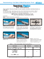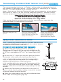
1
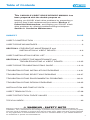
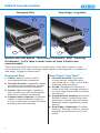
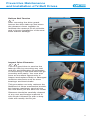
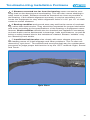
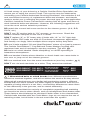
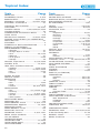
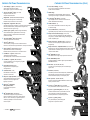
Service Manual
for
Industrial V-Belt Drives
Power Transmission Products, Inc.
U.S.A.
Customer Service: (866) 773-2926
CANADA
Customer Service: (866) 797-2358
www.carlislebelts.com
www.cptbelts.com
[email protected]
[email protected]
102163 (Rev ©2007) Carlisle Power Transmission Products, Inc.
Power Transmission Products, Inc.
Carlisle’s Full Power Transmission Line
1
*Power-Wedge® Cog-Belt® (3VX,5VX,8VX)
Space saving V-Belt transmits higher
HP and gives longer life for maximum savings.
3
Wedge-Band® (R3V,R5V,R8V,R3VX,R5VX,R8VX)
Carlisle's Power-Wedge belt in banded design.
Eliminates whip and turnover on narrow drives.
4
Wedge-Band® Chipper Drive Belt (R5VL)
Specially designed and constructed to meet the unique demands of
the forest products industry. Ideally suited for chipper saws,
debarker drives, head rigs and hogs.
3
4
5
6
Variable Speed Cog-Belt® (1228V through 6136V Series)
Carlisle Variable Speed Cog-Belt offers the same high
standard of quality in a replacement belt that Carlisle
provides to the OEM.
*Super Blue Ribbon® V-Belt (AP,BP,CP,DP)
The finest wrapped belt in the industry.
7
*Super II® V- Belt (A,B,C)
The revolutionary raw-edge® belt from Carlisle that blows
the cover off conventional wrapped belts due to its unique construction.
8
Super Vee-Band ® (RBP,RCP,RDP) Carlisle’s
Super Blue Ribbon V-Belt in banded design.
Eliminates belt whip and turnover on conventional drives.
9
Gold Ribbon™ Cog-Belt® (AX,BX,CX,DX)
The Energy Saver! More efficient
than ordinary belts. The finest classical V-belt available.
11
Double-Angle Belt (AA,BB,CC)
Designed for use on serpentine type
drive applications.
12
Vee-Ribbed™ Belt (J,L,M)
Increased HP in 2/3 the space
required for normal belts.
13
14
15
17
QD Bushings
Standardized for interchangeability. Tapered and fully
split through bore length for equivalent of interference fit.
18
Power-Wedge® QD Sheaves (3V,5V,8V)
High -capacity cast iron sheaves for use with narrow
V-Belts. Standardized QD bushings.
19
V-Ribbed Sheaves (J)
For use with V-ribbed belts. Precision form-cut grooves
for smooth running.
20
Classical QD Sheaves (AQ,BQ,CQ,DQ)
High-Quality heavy duty sheaves for classical (A,B,C,D) V-Belts.
21
Durapower Sheaves-Bushed Type (3L-4L,4L-5L)
Cast iron, for all types of light-duty and FHP applications
using 3L,4L,5L, A and B V-Belts. Bushing interchanges with
similar competitive types.
8
6
Gold Ribbon™ Cog-Band® (RBX,RCX,RDX)
A unique combination of our energy saving Cog-Belt
and the banded concept.
Thoro-Twist® V-Belting (3L,A,B,C,)
For use as an emergency replacement where endless
V-belts cannot be installed.
2
*Super Power-Wedge® V-Belt (3V, 5V,8V)
Designed for lower cost, more
compact multiple-belt drives.
10
16
1
2
5
Carlisle’s Full Power Transmission Line (Cont.)
7
9
10
Durapower Sheaves - Fixed Bore Type (3L-4L,4L-5L)
Cast iron, bore and keywayed to fit popular shaft sizes.
For light-duty.
23
Durapower Sheaves - Adjustable Diameter (3L-4L,4L-5L)
Rugged cast iron, two piece threaded assembly allows adjustment
of pitch diameter. Combination grooves for use with 3L,4L,5L,
A and B section V-Belts.
24
RPP® PANTHER (8M,14M)
The ultimate choice in high torque synchronous belt drives.
25
RPP® PANTHER Sprockets
Specially designed to handle the high torque transmitted by
PANTHER belt drives.
26
RPP PLUS® (3M, 5M, 8M,14M, 20M)
Up to 50% more power capacity than conventional high
torque drives.
27
Dual RPP® (D8M,D14M)
Dual sided synchronous belt with deep tooth parabolic profile
teeth allowing synchronous transmission via both the
external and internal pulleys in a multi-pulley drive.
28
RPP® Sprockets (5M,8M,14M,20M)
Precision companion to RPP and RPP PLUS belts on high
torque synchronous drives.
29
Synchro-Cog® Timing Belt (XL,L,H,XH,XXH)
For synchronization of driven speed to driver speed.
12
®
Durapower® ll (Raw Edge)
FHP Light Duty V-Belt
Longer belt life and improved
performance.
18
20
19
21
22
23
24
25
13
14
30
XDV® Xtra Duty V-Belt (38X,48X,58X)
The XDV belt is designed for tough belt drives;
typical of snowblowers, lawn mowers, garden tractors,
tillers, etc. Cover fabric design is geared to optimize
declutching capability for smooth and reliable
transfer of power.
17
22
11
Durapower Light duty V-Belt (3L,4L,5L)
Carlisle wrapped belt technology makes
Durapower a real heavyweight in the
light duty v-belt arena.
16
28
26
Synchro-Cog® Dual Timing Belt (DXL, DL, DH)
Provides maintenance-free synchronization from both
sides of the belt on positive drive applications.
Excellent performance on serpentine type drives.
27
15
31
Synchro-Cog® Timing Pulleys
(XL,L,H,XH,XXH) For perfect mating with
timing belts on synchronous drives.
29
* available in
construction
31
30
Table of Contents
This CARLISLE V-BELT DRIVE SERVICE MANUAL has
been prepared with the double purpose of:
Helping you AVOID V-belt drive problems by presenting a
step-by-step V-belt replacement procedure–Section 1:
Preventive Maintenance; and helping you SOLVE V-belt
drive problems by offering troubleshooting techniques–
Section 2: Corrective Maintenance.
SUBJECT
PAGE
V-BELT CONSTRUCTION ............................................................................2
V-BELT DRIVE ADVANTAGES ......................................................................3
SECTION 1–PREVENTIVE MAINTENANCE and
INSTALLATION of V-BELT DRIVES ......................................4-9
V-BELT INSTALLATION CHECK LIST ..........................................................9
SECTION 2–CORRECTIVE MAINTENANCE and
TROUBLESHOOTING of V-BELT DRIVES ......................10-35
V-BELT DRIVE TROUBLESHOOTING GUIDE ......................................12-13
TROUBLESHOOTING INSTALLATION PROBLEMS ............................14-21
TROUBLESHOOTING SELECTION PROBLEMS ................................22-27
TROUBLESHOOTING ENVIRONMENTAL PROBLEMS ......................28-31
TROUBLESHOOTING DESIGN PROBLEMS ........................................32-35
INSTALLATION AND TAKE-UP DATA ........................................................36
V-BELT TENSION TOOL ........................................................................37-38
V-BELT DEFLECTION FORCE VALUES ....................................................39
TOPICAL INDEX ..........................................................................................40
! WARNING - SAFETY NOTE
Failure to follow recommended application information and recommended procedures for
installation, care, maintenance and storage of products may result in failure to perform properly
and may result in damage to property and serious bodily injury. Make sure that product selected
for any application is recommended for that service. Contact Carlisle or your Carlisle distributor
for assistance or specific recommendations.
1
V-Belt Construction
Wrapped Belt
Raw Edge® Cog-Belt®
1
1
2
2
3
4
4
3
Before we talk about “Avoiding Problems” and “Solving
Problems”, let’s take a brief look at how V-belts are
constructed.
There are basically two types of construction. One has a fabric cover
surrounding it; the other–usually rated higher in horsepower–is made in a
raw edge, cogged construction.
Wrapped Belt
Raw Edge® Cog-Belt®
1. Cover–Woven cotton fabric
impregnated with neoprene.
1. Tension Section–Specially
woven stress-relieved fabric
stretches up to 176% more than
ordinary bias-cut fabric.
2. Cords–Synthetic Hi-Modulus
cords form the strength member
to carry high loads with minimum
stretching.
3. Compression Section–Exclusive
Stiflex® rubber compounds and
precision molded cogs increase
flexibility while supporting cords
evenly.
4. Raw Edge® Sidewalls–Provide
uniform, anti-slip surface, greater
flexibility and allows more cord
width.
2. Tension Section–Synthetic rubber
specially compounded to stretch
as belt bends around sheaves.
3. Cords–High-strength, synthetic
fiber cords carry the horsepower
load and minimize stretching.
4. Compression Section–Synthetic
rubber compounded to support
cords evenly and compress while
bending around sheaves.
2
V-Belt Drive Advantages
V-belt drives provide many maintenance advantages that help in your daily
struggle to reduce equipment repairs and to hold forced downtime to the
lowest possible level.
1. They are rugged–they will give years of
trouble-free performance when given
minimal attention...even under
adverse conditions.
2. They are clean–require no lubrication.
3. They are efficient–performing with an
average of 93-95% efficiency.
4. They are smooth starting and running.
5. They cover extremely wide horsepower
ranges.
6. They permit a wide range of driven
speeds, using standard electric motors.
7. They dampen vibration between driving
and driven machines.
8. They are quiet.
9. They act as a “safety fuse” in the powertrain.
10. V-belts and sheaves wear gradually–
making preventive and corrective
maintenance simple and easy.
3
Section 1
Preventive
Maintenance
and Installation
of V-Belt Drives
You will notice Reference Key
Numbers (such as A -1)appear
throughout this section. These refer
to a more detailed discussion with
illustrations relating to the subject in
Section 2 (Corrective Maintenance
and Troubleshooting).
Safety First
Before doing any maintenance work on power drives, be sure the controlling
switch is in the OFF position, locked out and tagged. Follow your plant’s
safety rules.
4
Preventive Maintenance
and Installation of V-Belt Drives
Relieve Belt Tension
A
-1
After removing the drive guard,
loosen the drive take-up and move
the sheaves closer together to
facilitate the removal of all old belts,
and to insure installation of the new
belts without damage.
Inspect Drive Elements
A -1 A -6
This is a good time to service the
take-up rails by removing any rust
and dirt, and lubricating as necessary
so tensioning of the new belts will go
smoothly and easily. You now also
have an excellent opportunity to
inspect and replace faulty or damaged
machine elements such as worn
bearings and bent shafts.
This procedure not only reduces the
likelihood of future mechanical trouble,
but insures maximum service from
the new belts you are about to install.
Sheaves should be carefully cleaned
of any rust and foreign material. A
wire brush followed up with a shop
cloth will usually do the job.
5
Section 1
Inspect Sheaves
A -4 A -9
Sheave condition and alignment are
vital to V-belt life and performance.
New V-belts should never be installed
without a careful and thorough
inspection of the sheaves involved.
Particular attention should be given
to these conditions:
a. Worn Groove Sidewalls
b. Shiny Sheave Groove Bottom
c. Wobbling Sheaves
d. Damaged Sheaves
Shiny Sheave Groove Bottom
Worn Groove Sidewalls
Wobbling Sheaves
Damaged Sheaves
Align Sheaves (Preliminary)
A -3
A -5
Alignment should be given preliminary consideration at this time.
Check to make sure that:
a. The shaft of the DriveR and the DriveN sheaves are parallel,
horizontally and vertically.
b. The DriveR and DriveN sheaves are in a straight line.
c. Both sheaves are properly mounted and as near to the bearings
as practical.
6
Preventive Maintenance
and Installation of V-Belt Drives
Select Replacement Belts
B -1
B -4
B -2
B -3
After you have made any necessary corrections in your V-belt drive elements, the next step is the selection of the right replacement belts.
In replacing sets of V-belts, here are some Very Important Reminders:
• NEVER MIX NEW AND USED BELTS ON A DRIVE.
• NEVER MIX BELTS FROM MORE THAN ONE MANUFACTURER.
• ALWAYS REPLACE WITH THE RIGHT TYPE OF V-BELT.
• ALWAYS OBSERVE V-BELT MATCHING LIMITS.
Installing New Belts
A -1
Place the new belts on the sheaves,
and be sure that the slack of each
belt is on the same side. You can do
this by pressing the belts with your
hand to bring the slack on one side
of the drive. Loosening the drive
take-up in advance makes this easy.
Right
Do not force the belts on the
sheaves by using a pry bar or by
rolling the sheaves. Now, move
sheaves apart until the belts are
seated in the grooves, and make
preliminary tightening of the drive,
just until the slack is taken up.
Wrong
7
Section 1
Apply Tension
A -7
A -8
All V-belt drives must operate under proper tension to produce the wedging
action of the belt against the groove sidewall. A well-established rule of
thumb is that the best tension for a V-belt drive is the LEAST tension at
which the drive will not slip under peak load.
Most V-belt problems are due to
improper tensioning. Several tools and
methods are available to insure proper
tensioning. A simple and easy to use
option is the Tension-Finder™ available
only from Carlisle.
Run the drive for about 15 minutes.
Then apply full load and check for
slipping. Should slipping occur, further tension should be applied.
After the drive has operated under load long enough for the belts to
become seated and adjusted (approximately 24 hours), it is a good idea to
make a final tension inspection.
For a complete discussion on tensioning and slippage, refer to Section 2
A -7, in this manual.
You have now completed a practical procedure for replacing V-belts that
should help you AVOID problems with your V-belt drives. The check list on
page 9 serves to summarize the points discussed in this section.
Check Sheave Alignment (Final)
A -3
One of the advantages of V-belt drives is the fact that perfect alignment of
sheaves is not critical to the operation of the drive–V-belts tolerate
mis-alignment of up to 1/16 inch per 12 inches of shaft center distance.
However, the closer you can come to perfect alignment, the better.
Laser Alignment
A -3
Use a laser alignment tool or straight edge to check alignment. The straight
edge should make contact at four distinct points along the outside perimeter
of both sheaves.
Contact points
Straight edge
Refer to Section 2,
procedures.
Laser alignment tool
A
-3, for complete discussion of proper alignment
Note: Sheaves should always be mounted as close to the bearings as
practical to avoid excessive loads on bearings and shafts.
8
Preventive Maintenance
and Installation of V-Belt Drives
V-Belt Installation Check List
! 1. Cut off and lock out power source.
Observe all other safety procedures.
! 2. Remove belt guard.
! 3. Loosen motor mounts.
! 4. Shorten center distance.
! 5. Remove old belts.
! 6. Inspect belt wear patterns for possible
troubleshooting.
! 7. Inspect drive elements–bearings,
shaft, etc.
! 8. Inspect sheaves for wear and clean.
! 9. Check sheave alignment. (preliminary)
! 10. Select proper replacement belts.
! 11. Install new belts.
! 12. Tension belts.
! 13. Check sheave alignment. (final)
! 14. Replace guard.
! 15. Start drive (look & listen).
! 16. Re-tension after 24 hours.
9
Section 2
Corrective
Maintenance
and Troubleshooting
of V-Belt Drives
The first section of this V-Belt
Service Manual outlined a step-bystep procedure for the installation of
replacement V-belts to help you
prevent V-belt maintenance problems.
The reason behind these steps is
also fundamental in the daily inspection and maintenance of V-belt
drives. Watching and listening will
alert you to warning signs of trouble,
since one of the greatest advantages
of V-belt drives is the fact that belts
and sheaves wear gradually. You
can spot potential problems in time
to arrange a short, scheduled maintenance down-time instead of experiencing a longer, costly interruption
of production when unexpected
trouble occurs.
V-belts may be thought of as being
much like electrical fuses–their
unexpected failure is usually a signal
that something else in the system is
wrong. Even their patterns of gradual
wear can often indicate conditions
needing corrections or improvement.
10
Corrective Maintenance
and Troubleshooting of V-Belt Drives
How to correct maintenance problems by using Carlisle’s
Quick Reference Troubleshooting Guide
The V-Belt Drive Troubleshooting Guide presented on the following pages
represents knowledge acquired by Carlisle in the development and manufacture of V-belts for almost 100 years.
This quick-reference guide lists the most common symptoms or warning
signs of drive problems and then indicates possible causes.
Each possible cause is further referenced by a key number (such as A -1)
which indicates where you may find the cure in a more detailed discussion
of the subject in this section of the manual.
These discussions are grouped into four major sections:
A
Troubleshooting INSTALLATION Problems
B
Troubleshooting SELECTION Problems
C
Troubleshooting ENVIRONMENTAL Problems
D
Troubleshooting DRIVE DESIGN Problems
Practical, non-technical troubleshooting tips are included to help you to
quickly identify and correct suspected problems.
11
Worn Cover On Back
❉
Belt Turns Over Or Jumps Off Sheave
●
●
❉
A-5
A-4
Worn Or Damaged Sheaves
●
Sheaves Too Far From Bearing
A-3
Rapid Sidewall Wear
Sheaves Misaligned
SYMPTOMS
A-2
CAUSES
Belts Rubbing Guard
CURES
Belts Pried On Or Misplaced Slack
A-1
Corrective Maintenance
and Troubleshooting of V-Belt Drives
●
●
Belt Soft, Swollen
❉
Belt Slips, Squeals (Spin Burn)
❉
Belt Cover Split
●
Underside Cracked
●
Tie-Band Damaged
●
❉
●
Repeated Breakage
Belts Ride Too High
Belts Bottoming
❉
Repeated Take-up Necessary
●
Belts Vibrate Excessively Or Appear Mismatched
●
●
Bearings Are Hot
●
●
Shafts Whip Or Bend
●
●
Cracked Bushings
●
Sheave Wobble
●
❉ Indicates most common causes ● Indicates other possible causes
12
●
●
●
●
●
❉
●
●
●
●
●
●
❉
●
❉
●
A-7
A-8
A-9
B-1
B-2
Insufficient Tension
Excessive Tension
Improper Sheave Installation
Belts Worn (Normal Service Life)
Wrong Belt Cross-Section Or Type
C-2
C-3
C-4
C-5
C-6
C-7
D-1
D-2
D-3
Excessive Heat
Excessive Oil Or Grease
Use of Belt Dressing
Abrasive Environment
Foreign Objects In Grooves
Excessive Moisture
Overloaded Drive/Underbelting
Drive Seriously Overbelted
Sheaves Too Small
●
●
●
●
●
❉
❉
●
●
●
❉
●
❉
●
●
●
●
●
●
❉
❉
●
●
●
●
●
D-5
D-6
Backside Idler
Harmonics
Insufficient Wrap On Small Sheave D-4
C-1
Machine-Induced Impulse Or Shock B-4
Mismatched Belts Or Mixed Brands B-3
A-6
Poor Bearing Or Shaft Condition
Improper Or Prolonged Storage
●
●
●
●
●
●
●
❉
❉
❉
●
●
❉
●
❉
❉
13
Troubleshooting
Installation
Problems
As pointed out in Section 1 of this
manual, preventive maintenance by
using proper installation techniques
is important for long, trouble-free
V-belt service.
Occasionally, however, you will find
it necessary to correct problems
caused by improper installation.
This section deals with these
problems and troubleshooting
procedures.
14
Troubleshooting Installation Problems
-1 Prying or forcing V-belts onto
the sheaves can, and usually does,
break some of the load-carrying
tensile cords (see photo on page 7,
Section 1). When this happens, the
belt may either break or turn over in
the groove, usually within the first
few minutes of operation. This
method of installation may be
evidenced by a rupture or split in the
wrapped cover of the belt, caused
by the prying tool or sheave edge.
Broken cords are easily identifiable
on raw-edge V-belts, because it is
usually the edge cords that break
first.
A
Misplaced Slack can also cause
belt breakage, again usually on
startup. This occurs on multiple-belt
drives when all of the belt slack is
not brought to the same side of the
drive before tensioning. If some
belts are tight on one side, and
others are tight on the other side,
the heavy shock load of starting will
be borne by only some of the belts,
thus weakening or breaking the
load-carrying cords.
Ruptured Cover
A -2 Belts rubbing against the metal
guard or other obstruction will be
evidenced by cut or worn fabric on the
back or upper edge of the V-belt. Often
just replacing missing bolts in guard
brackets will remedy this situation.
Fabric Worn on
Backside
15
A
A -3 Misaligned sheaves can
cause rapid wear of the V-belt sidewalls, considerably shortening service
life of both belts and sheaves.
Mis-alignment can also cause
separation of the tie-band on banded
belts, or apparent mismatching of
individual belts. V-belt sheave alignment should be within a tolerance of
1/16” per 12” of drive center
distance.
The three basic types of sheave
and shaft misalignment are shown
below, with suggested methods for
checking and correcting each type.
Note that all 3 types may exist at
the same time. Alignment should be
checked and corrected in the order
given.
Sidewall Wear
Horizontal
Angular
16
Vertical
Angular
Parallel
Troubleshooting Installation Problems
1. Horizontal Angular (shafts in same horizontal plane but not parallel)
To Check: Use straightedge or string near sheave centers.
To Correct: Loosen motor mounting bolts and rotate motor until all 4
points touch straightedge.
2. Vertical Angular (shafts in same vertical plane but not parallel)
To Check: Place straightedge about 4 radius from the outside diameter
of both sheaves as shown 1. Repeat on opposite side of shaft 2.
Straightedge should touch 4 points indicated in each position.
To Correct: Use shims under motor base in front or rear of motor,
depending on type of correction required.
3. Parallel (shafts are parallel; sheaves not in line)
To Check: Use straightedge or string near sheave centers.
To Correct: Loosen sheave so it slides easily on shaft until all 4 points
touch straightedge. Retighten sheave in position. Important: Sheave
should be mounted as close to bearing as possible to reduce overhung
load on bearing. Re-locate equipment if necessary.
17
A
-4 Worn or damaged sheaves are an even greater cause of rapid belt
wear, slippage and vibration. Badly worn sheaves can cause over-tensioning
of the drive to prevent slippage, indirectly causing over-heated bearings and
shaft damage. If pieces of the sheave flange are missing, it will result in
badly worn sidewalls of the belt, and the resulting sheave imbalance can
damage bearings and create a safety hazard. When only some of the
grooves are worn more than others, the effect is that the belts appear to be
mis-matched. It also causes “differential driving,” where only some of the
belts are carrying the entire load of the drive.
A
In the case of banded belts, worn grooves cause the belts to ride too low in
the grooves, thus causing the tie-band to wear against the sheave flanges
between the grooves. In severe cases, this can have the same effect as a
circular blade, cutting the band and separating the belts.
Sheave templates are available from your Carlisle distributor, which can be
used to check grooves accurately for wear. A flashlight held behind the template when placed in the groove will help you to observe the amount of
wear. “Dishing” should not exceed 1/32” for individual V-belts, or 1/64” for
banded V-belts. A shiny groove bottom is a sign that the belt or sheave, or
both are badly worn and the belt is bottoming in the groove. Worn sheaves
or shiny sheave groove bottoms will show up first on the smaller sheave.
The cost of replacing a worn sheave will be more than recovered in longer
V-belt life, reduced maintenance and downtime.
Worn Sidewalls
Proper Position of Belt in
Sheave
18
Cut Tie-Band
Bottoming and Dishing of
Belt in Sheave
Troubleshooting Installation Problems
-5 Sheaves mounted too far from the bearing cause excessive overhung load on the bearing and overheating. This can also cause shafting to
whip, bend or break. Sheaves should be mounted as close as possible to
the bearing. If this affects alignment severely, it may be necessary to relocate the equipment to stay within alignment limits of 1/16” per 12” of shaft
center-to-center distance.
A
A -6 Bearing condition and normal wear may well be the cause of overheating, rather than belt tension. They should be inspected for proper lubrication
and wear according to the specifications of the bearing or equipment manufacturer. Shaft condition should also be checked and replaced if necessary,
as bent shafts can be detrimental to bearings, belts and sheaves, as well as
being a safety hazard due to the imbalance created. Sheave “wobble” may
be caused by bent shafts.
A -7 Insufficient belt tension vies closely with worn sheave grooves as
the leading cause of V-belt slippage and other problems. This is often evidenced by “spin burn”. The easiest and most practical way for maintenance
personnel to judge proper belt tension is by the “SST” method–Sight, Sound
and Touch.
Spin Burn
19
A
Sight–While the drive is operating,
look for a slight “bow” or “sag” in
the slack side of the belts. This is
normal, and should appear more
noticeable under heavy load, such
as at startup or during the load
cycles of an air compressor, for
instance. Check the sheave
grooves for wear.
Sound–Properly designed V-belt
drives should not squeal or howl
under peak load conditions, such
as on startup of a centrifugal fan. If
necessary, stop the drive, then start
it again. If a squeal is heard, the
belts should be tightened just to the
point where they do not squeal
under peak load. Newly installed
belts require about 24 hours to
become fully seated in the grooves,
so a little extra tension and a
recheck the next day are called for.
Touch–V-belts don’t always squeal
when they are slipping. If slippage
is suspected, a sure way of determining it is by stopping the drive
(lock it out!) and placing your bare
finger against the inside of a
sheave groove. If slippage is present, it will generate enough heat so
that you can’t keep you finger on
the groove. If this is true, and there
is no outside heat source, then the
drive is probably slipping.
Assuming no sheave wear, the
drive should be tightened. If the
sheave is worn, replace the sheave
and tension normally. Use the
various tensioning tools that are
available from Carlisle to assure
proper tensioning.
20
Troubleshooting Installation Problems
-8 Excessive tension on V-belts can be even more detrimental than too
little tension, affecting not only the belts, but also bearings and shafts.
Again, the best rule is to apply only enough tension on the belts to keep
them from slipping during startup or peak loading. Some indicators of
excessive tensioning (but not always) are:
A
• Repeated belt breakage
• Excessive vibration
• Overheated bearings
• Whipping or bent shafts
A -9 Improper sheave and bushing installation can result in sheave
“wobble” as well as causing bushings or sheave hubs to crack. When
installing split-tapered bushings such as QD® or Taper-Lock types, always
follow manufacturer’s instructions.
It is important to never lubricate the tapered surfaces before installing. The
lubrication will permit recommended torque wrench values to increase the
actual force on the bushing and hub. This usually results in cracking of the
bushings at the bolt hole or keyway.
On flanged bushing types, the flange should never be brought up flush with
the sheave hub face. A small gap between the two surfaces is normal.
When removing split-tapered bushings, start at the jack-screw hole
opposite the split, to avoid cracking the bushing.
Cracked Bushing
Recommened Wrench Torque Values To Use In Tightening QD Bushings
Bushing Size
QT
JA
SH-SDS-SD
SK
SF
E
F
J
M
N
P
W
S
Cap Screw
Size & Thread
Foot Pounds
Torque Wrench
Normal Applications*
1/4-1
No. 10-24
1/4-20
5/16-18
3/8-16
1/2-13
9/16-12
5/8-11
3/4-10
7/8-9
1-8
1-1/8-7
1-1/4-7
9
5
9
15
30
60
110
135
225
300
450
600
750
* For severe (rock-crusher type applications) these values can be increased by a maximum
of 50%. On severe applications the bolt torque should be rechecked at periodic intervals
during operation.
21
B
Troubleshooting
Selection Problems
The array of V-belt types, crosssections and lengths on the market
today are all part of technological
efforts to provide more efficient,
cost-saving answers to your drive
requirements.
This category is intended to point
out how you can be sure of applying
the best Carlisle V-belt type to your
applications.
22
Troubleshooting Selection Problems
B -1 Worn V-belts may have gotten that way simply because they have
delivered the service life built into them. Carlisle, like other manufacturers,
strives to build V-belts with a “balanced” construction, so each element of
the belt will last as long as all other elements. But the wide variety of industrial
applications, environmental conditions and maintenance practices makes
this impossible to achieve. However, the expected life of an industrial V-belt
on a properly designed drive is 3 years.
B -2 Using the wrong V-belt cross-section or type can create problems
for you...and it’s not hard to do, since many have similar dimensions. For
example, the following Carlisle V-belts have approximately the same top
width (5/8”) and length (85” O.C.):
And yet, the horsepower ratings of these belts range from as little as 2.2 HP
per belt to as much as 11.9 HP per belt. on a 5” diameter sheave and 1750
RPM motor!
5/8"
5L
11/32"
5L850 Durapower®
Light Duty FHP V-Belt
5/8"
58X
11/32"
58X850 XDV® Premium V-Belt
21/32"
BP
7/16"
BP82 Super Blue Ribbon® V-Belt
7/16"
BX82 Gold Ribbon™ Cog-Belt®
17/32"
5VX850 Power-Wedge® Cog-Belt®
21/32"
5/8"
23
B
A V-belt survey of your drives by a Carlisle Certified Drive Specialist can
assure you of using the correct V-belt. This service may be obtained by
contacting your Carlisle Authorized Stocking Distributor. He maintains a full
and convenient inventory of replacement belts and sheaves, and stands
ready to assist you in selecting the proper size and type for each application.
Carlisle’s Industrial Power Transmission catalog lists all types and sizes of
stock industrial belts and sheaves. However, the following suggestions will
cover the most serious selection problems:
DO match the correct belt cross-section to the sheave groove. (A-A, B-B,
5V-5V, etc.)
DON’T use “B” section belts in “5V” grooves, or vice-versa. Check the
sheave number stamped on the rim if in doubt.
DON’T replace “A” or “B” heavy duty V-belts with “4L” or “5L” light duty
(FHP) V-belts. FHP belts are built for Fractional Horsepower applications,
and usually run singly. Most multiple drives require heavy duty belts.
DO use V-belts marked “Oil and Heat Resistant” where oil or heat is present.
The Carlisle Gold Ribbon™ Cog-Belt and Power-Wedge Cog-Belt offer
maximum heat and oil resistance–see key numbers C-2 and C-3
DO insist on a belt labeled “Static-dissipating” on drives operating in
hazardous atmospheres.
DO use banded V-belts where vibration or shock loads can cause belts to
turn over or jump out of the sheave grooves.
DO use matched sets from the same manufacturer (see key number
B
-3)
DON’T mix old and new belts on a drive. They cannot be matched.
GOLD RIBBON™ COG-BELT®
GOLD RIBBON™ COG-BELT®
OIL HEAT RESISTANT
STATIC DISSIPATING
OIL HEAT RESISTANT
STATIC DISSIPATING
MADE IN
U.S.A.
MADE IN
U.S.A.
BX62
BX62
B -3 Mismatched belts or mixed brands from different manufacturers
cannot be matched together, and will not deliver the service life they should.
Although all manufacturers use similar belt numbering systems, different
brands with the same number will differ slightly in dimensions and are not
capable of being mixed in a set. Also, construction differences cause them
to ride differently in the grooves, and to stretch differently.
It should be noted that the majority of complaints regarding belt matching
are found to be due to other causes, such as misalignment and sheave wear.
These factors should always be checked if belts seem to be mismatched.
Carlisle belts branded with the Chek-MateTM logo do not require the use of
matching codes, but all belts in the set must bear this symbol.
24
Troubleshooting Selection Problems
-4 Machine-induced vibration or shock loads frequently can cause
V-belts to whip or even jump off the drive, creating a safety hazard, and of
course, damaging the belts.
B
On multiple-belt drives, this whipping can be reduced or eliminated by using
banded V-belts. A banded V-belt consists of from 2 to 5 individual V-belts
joined together with a bonded, reinforced tie-band (see illustration).
These belts will ride slightly higher in the sheave grooves to provide clearance
between the band and the sheave flange. Because of this, sheave grooves
should not be worn or “dished-out” more than 1/64”. Also, because they are
banded together, alignment of the sheaves is somewhat more critical.
Belts riding slightly higher
in the sheave grooves.
(The chart on the next page will be helpful in selecting the best Carlisle
belt for an application.)
25
B
V-Belt Selection Guide
Generic Belt Type
(Cross-Sections)
Normal
HP Range
Maximum
Belt Speed
(FT/Min)(1)
Super Blue
Ribbon
Classical Multiple
(A, B, C, D)
1-500
6500
Super ll
Classical Multiple
(A, B, C, D)
1-500
6500
Gold Ribbon
Cog-Belt
Classical Cogged
Multiple (AX, BX, CX, DX)
1-500
6500
Super
Power-Wedge
Narrow Multiple
(3V, 5V, 8V)
1-1000
6500
Power-Wedge
Cog-Belt
Narrow Cogged
Multiple (3VX, 5VX)
1-600
6500
Classical Banded
(RB, RC, RD)
1-500
6500
Gold Ribbon
Cog-Band
Classical Cogged Banded
(Premium HP)
(RBX, RCX, RDX)
1-500
6500
Wedge-Band
Narrow Banded
(R3V, R5V, R8V)
1-1000
6500
Double
Angle
Double-V Belts
(AA, BB, CC, DD)
1-200
6500
Variable Speed
(1228V-6136V)
21-100
6500
V-Ribbed
(J, L, M)
4-500
6000
Thoro-Twist
Link (Segmented)
(3LTwist, ATwist, BTwist, CTwist)
1-300
5000
(1000 min.)
Durapower
FHP
(2L, 3L, 4L, 5L)
Light Duty
6500
Durapower ll
FHP
(2L, 3L, 4L, 5L)
Light Duty
6500
XDV
Premium FHP
(38X, 48X, 58X)
Light Duty
6500
Carlisle Brand
Super
Vee-Band
Variable Speed
Cog-Belt
Vee-Rib
Notes: (1) Normally limited by sheave materials. (2) Expect little or no life loss due to heat.
26
Troubleshooting Selection Problems
Normal
Temp. Range
(˚F)(2)
Oil/Heat
Resistance
Static
Dissipating
General Application
Min.
Max.
-35
120
Good
✔
General-Purpose Heavy Duty
Industrial Drives.
-35
120
Good
✔
General-Purpose Heavy Duty
Industrial Drives.
-35
130
Excellent
✔
Longer Life, High Efficiency,
Small Diameters.
-35
130
Very
Good
✔
High-Performance, Compact
Industrial Drives, Long C.D.
-35
130
Excellent
✔
High-Performance, Compact
Industrial Drives, Short C.D.
-35
120
Good
✔
Reduces Belt Whip, Turnover
on Pulsating, Surge Loads.
-35
130
Excellent
✔
Longer Life, High Efficiency,
Reduces Belt Whip, Turnover
on Pulsating, Surge Loads
-35
130
Very
Good
✔
Reduces Belt Whip, Turnover
on Pulsating, Surge Loads
-35
120
Good
Special Order
-35
130
Excellent
✔
Wide-Range Variable
Sheaves
-35
130
Very
Good
No
Small Diameters, High Speed
Ratios, Compact
-35
130
Excellent
No
Emergency Replacement
Fixed Center Distance
-35
120
Fair
✔
Light Duty Drives
Using a Single Belt
-35
120
Fair
✔
Light Duty Drives
Using a Single Belt
-35
130
Very
Good
No
Longer Life on FHP Drives,
Clutching Lawn/Garden
Drives
Available in
Serpentine Drives
construction
27
C
Troubleshooting
Environmental
Problems
“Environmental Protection” can be
as important for a V-belt as for
humans. This section deals with the
effect of adverse environmental
conditions on V-belts, and how you
can minimize these effects.
28
Troubleshooting
Environmental Problems
C -1 Improper or prolonged storage can reduce service life considerably.
V-belts should be stored in a cool, dry place with no direct sunlight. On shelves
in boxes or piles, the stack should be small enough to avoid excess weight
and distortion on the bottom belts. On pegs, the longer belts should be coiled
in loops of suitable size to prevent distortion from the weight of the belt.
The following guide provided by the RMA should be followed for optimum
conditions:
Guide to Maximum Number of
Coilings of V-Belts of Storage
Belt
Cross Section
Belt Length
(Inches)
Number
of Coilings*
Number
of Loops*
A,AA,**3V
and B
Under 60.0
60.0 to 120.0
120.0 to 180.0
180.0 and up
None
1
2
3
1
3
5
7
BB,**C,
and 5V
Under 75.0
75.0 to 144.0
144.0 to 240.0
240.0 and up
None
1
2
3
1
3
5
7
D
Under 120.0
120.0 to 240.0
240.0 to 330.0
330.0 to 420.0
420.0 and up
None
1
2
3
4
1
3
5
7
9
E and 8V
Under 180.0
180.0 to 270.0
270.0 to 390.0
390.0 to 480.0
480.0 and up
None
1
2
3
4
1
3
5
7
9
*One coiling results in three loops; two coilings result in five loops, etc.
**“AA” and “BB” are known as “double angle” or “hexagonal” V-belts.
The pegs should be crescent shaped in cross-section to avoid compression
set dents in the belts from sharp corners and the pegs should be sufficiently
large in cross-section to avoid compression setting into sharp bends resulting
from the weight of the hanging belts.
It is recognized that belts are sometimes coiled in smaller loops for packaging
for shipment than indicated in the above table, but such packaging should
not be for prolonged storage.
29
C
C -2 Excessive heat
Standard construction V-belts (such as Carlisle’s Super Blue Ribbon) are
compounded for moderate resistance, and should give adequate service
under normal conditions.
Belt temperature (not ambient or surrounding air temperature) is the determining factor when heat is a suspected cause of short belt life.
Tests have shown that the service life of a V-belt is cut in half for every
18˚F raise in belt temperature.
Troubleshooting Belt Temperature
A good general rule for checking belt temperature without sophisticated
instruments is to stop the drive (lock it out!) and touch the belt with your hand.
If you can grasp if firmly for at least 5 seconds, the belt temperature is
probably not over 140˚F and therefore not beyond the operating range for
most V-belts. However, if you can’t hold it for at least 5 seconds, the belt
temperature is probably well over 140˚F, and heat is contributing to short
belt life.
Further evidence of heat may be the appearance of small cracks on the
underside of the belt.
What to do about excessive heat:
1. Check for slippage (see key number A -7).
2. Ventilate the drive or shield from heat source.
3. Replace belts with specially compounded heat-resistant belts (such as
Carlisle’s Gold Ribbon or Power-Wedge Cog-Belt).
Heat Cracks
C -3 Excessive oil or grease
Standard construction V-belts (such as Carlisle’s Super Blue Ribbon) are
compounded for moderate grease and oil resistance. However, an excessive
amount can cause softening, swelling and deterioration of the rubber compounds, as well as slippage.
What to do about oil or grease:
1. When there is occasional exposure from spillage or leakage, the belts
and sheave grooves should be cleaned with a mixture of detergent and
water–after the drive has been locked out and cause of leakage corrected.
2. When belts cannot be protected from oil, specially compounded oilresistant V-belts (such as Carlisle’s Gold Ribbon or Power-Wedge CogBelt) should be used.
30
Troubleshooting
Environmental Problems
-4 Never apply so-called “belt
dressings” to V-belts. These compounds are usually made from a
petroleum derivative and can have a
destructive effect on rubber compounds and other components of the
belt. If belts slip, check for adequate
tension and/or worn sheave grooves
(see A -4, A -7).
C
C -5 Abrasive conditions from
sand, dust or grit can accelerate
wear of both belts and sheaves.
This is especially true when slippage
is present. Belt selection can be an
important factor. Experience has
shown that raw-edge constructions
reduce this wear because they
reduce the “sandpaper-effect” caused
by slippage. Drives should be wellshielded against excessive abrasive
particles as much as possible.
-6 Foreign objects, such as wood
chips, can create havoc with V-belt
drives. Belt breakage and turnover
are the most common symptoms.
Shielding the drive is a necessity.
Belt guards with expanded metal
screening are often used, but ventilation is sometimes sacrificed, possibly
requiring additional cooling. Banding
belts are often effective, since they
eliminate belt turnover.
C
Abrasive Wear
-7 Excessive moisture can
penetrate the fabric covering of a
V-belt, causing deterioration. In
addition, a large amount of water
can reduce friction and cause slippage. Belt drives should be protected
as much as possible when used
outside or when subject to spray
from washdown hoses, etc. Belt
tension should be inspected regularly.
C
31
D
Troubleshooting
Design Problems
When normal corrective measures
as discussed in the previous sections
do not seem to produce the desired
results, an inherent design problem
may be the culprit. The solutions to
these are best left up to the plant
engineering department or a Certified
Drive Specialist. However, the discussion presented in this section will
help identify symptoms caused by
design problems.
32
Troubleshooting Design Problems
D -1 Underbelting a drive, (using
fewer belts than recommended by
good design practice) results in
excessive tension in each belt on
the drive.
This is commonly evidenced by
excessive stretching which requires
frequent take-ups to prevent slippage.
Another warning sign can be repeated
belt breakage.
In many cases, underbelting can be
corrected simply by using raw edge,
cogged V-belts which have a higher
horsepower rating. When these are
used, drives should be identified to
assure that future replacements are
made with this type of belt.
D -2 Drive overbelting, while usually
resulting in longer V-belt life, can be
just as serious as underbelting. The
symptoms most commonly found
are overheated bearings and bent
shafts.
When too many belts are on the
drive, the total tension can be
excessive when “table” values are
used. On the other hand, when too
few belts are on the drive, tension
values from these tables may be
inadequate.
D -6 Belt Vibration, is a
not-so-common problem resulting
from tension harmonics. Since
induced vibration can be caused by
several factors, this should be
referred to plant engineering.
33
D
D -3 When sheaves are too small for the belt cross-section, the belt flexes
beyond its normal limits. This is usually evidenced by cracks on the underside of the belt. Table A indicates the minimum recommended sheave diameter
for flexing each belt cross-section. In most cases, use of a raw-edge cogged
belt will improve service life greatly, due to its greater flexibility.
Table A. Minimum Recommended Sheave and Idler Diameters
V-Belt
Cross Section
Minimum P.D.
Sheave or Inside Idler
Minimum O.D.
Flat Backside Idler*
A, AP
3.0
4.5
B, BP
5.0
7.5
C, CP
9.0
13.5
D, DP
13.0
19.5
E, EP
21.0
31.5
AX
2.6
4.0
BX
4.0
6.0
CX
7.0
10.5
DX
11.0
16.5
3V
2.6
__
3VX
2.2
__
5V
7.0
__
5VX
4.3
__
8V
12.4
__
8VX
11.2
__
*Note: Backside Idlers are detrimental to V-belt service life.
Another problem caused by sheaves that are too small is overheating of
motor bearings, or even bent shafts. NEMA publishes minimum recommended
sheave diameters for use with electric motors to avoid excessive bearing
loads. Table B shows these minimums for the most common motor types.
General purpose motors having continuous time rating with the frame sizes,
horsepower and speed ratings listed in the following are designed to operate
with V-belt sheaves within the limiting dimensions listed. Selection of V-belt
sheave dimensions is made by the V-belt drive vendor and the motor purchaser
but, to assure satisfactory motor operation, the selected pitch diameter shall
be no smaller than the dimensions listed on the next page.
34
Troubleshooting Design Problems
Table B. Application of V-Belt Sheave Dimensions to General Purpose Motors
Integral-Horsepower Motors–
Polyphase Indcuction
Frame
Number
3600
143T
145T
182T
182T
184T
184T
184T
213T
215T
215T
254T
254T
256T
256T
284T
284T
286T
324T
326T
364T
364T
365T
365T
404T
404T
404T
405T
405T
405T
444T
444T
444T
444T
445T
445T
445T
445T
12
2-3
3
5
…
5
72
72-10
10
15
15
20
20-25
…
…
…
…
…
…
…
…
…
…
…
…
…
…
…
…
…
…
…
…
…
…
…
…
Horsepower at
Synchronous Speed, Rpm
1800
1200
900
1
12-2
3
…
…
…
5
72
…
10
…
15
…
20
…
25
30
40
50
…
60
…
75
…
…
100
…
100
125
…
…
125
150
…
…
150
200
w
1
12
…
2
…
…
3
5
…
72
…
10
…
15
…
20
25
30
40
…
50
…
60
…
…
75
…
…
100
…
…
…
125
…
…
…
2
w
1
…
12
…
…
2
3
…
5
…
72
…
10
…
15
20
25
30
…
40
…
…
50
…
60
…
…
…
75
…
…
…
100
…
…
Conventional
A,B,C,D & E
Minimum
Pitch
Diameter,
Inches
2.2
2.4
2.4
2.6
2.4
2.6
3.0
3.0
3.0
3.8
3.8
4.4
4.4
4.6
4.6
5.0
5.4
6.0
6.8
6.8
7.4
8.2
9.0
9.0
9.0
10.0
10.0
10.0
11.5
11.0
10.5
11.0
…
12.5
12.5
…
…
V-belt Sheave
Narrow
3V,5V, & 8V
Minimum
Outside
Diameter,
Inches
2.2
2.4
2.4
2.4
2.4
2.4
3.0
3.0
3.0
3.8
3.8
4.4
4.4
4.4
4.4
4.4
5.2
6.0
6.8
6.8
7.4
8.2
8.6
8.0
8.4
8.6
10.0
8.6
10.5
10.0
9.5
9.5
10.5
12.0
12.0
10.5
13.2
NEMA Standard, MG1-14.42
-4 Insufficient wrap on the small sheave can require excessive belt tension
to prevent slippage. This condition may require re-design, either using more
belts, increasing the center distance or using a backside idler with longer belts.
This is again a matter for plant engineering.
D
-5 Backside idlers can create their own problems, because they cause V-belts
to bend opposite to the way they were designed. Care must be taken to see
that a backside idler is large enough in diameter to reduce harmful stresses,
which often cause cracks on the underside of the belt. Table A (under D -3) also
shows these minimum recommended diameters.
D
Full technical information regarding proper V-belt design can be found in the
Carlisle Engineering Guide for Industrial V-Belt Drives available from your
Carlisle distributor.
35
INSTALLATION AND TAKE-UP DATA
TABLE 3 POWER-WEDGE/SUPER POWER-WEDGE V-BELTS CENTER
DISTANCE ALLOWANCE FOR INSTALLATION AND TAKE-UP (INCHES)
Standard
Length
Designation
For Take-Up
(Add)
For Installation (Subtract)
3VX
3V
3V
Banded
5VX
5V
5V
Banded
250 thru 475
500 thru 710
750 thru 1060
0.5
0.8
0.8
1.2
1.4
1.4
—
1.0
1.0
—
2.1
2.1
1120 thru 1250
1320 thru 1700
1800 thru 2000
0.8
0.8
—
1.4
1.4
—
1.0
1.0
1.0
2120 thru 2360
2500 thru 2650
2800 thru 3000
—
—
—
—
—
—
3150 thru 3550
3750
4000 thru 5000
—
—
—
—
—
—
8VX
8V
8V
Banded
All
Cross
—
—
1.5
—
—
3.4
1.0
1.2
1.5
2.1
2.
2.1
1.5
1.5
1.8
3.4
3.4
3.6
1.8
2.2
2.5
1.2
1.2
1.2
2.4
2.4
2.4
1.8
1.8
1.8
3.6
3.6
3.6
3.0
3.2
3.5
1.2
—
—
2.4
—
—
2.0
2.0
2.0
4.0
4.0
4.0
4.0
4.5
5.5
Sections
TABLE 4 CLASSICAL V-BELTS CENTER
DISTANCE ALLOWANCE FOR INSTALLATION AND TAKE-UP (INCHES)
Standard
Length
Designation
A, AX
AP
B, BX
BP
BX & BP
Banded
21 thru 35
36 thru 55
56 thru 85
0.75
0.75
0.75
1.00
1.00
1.25
1.50
1.50
1.60
86 thru 112
116 thru 144
148 thru 180
1.00
1.00
—
1.25
1.25
1.25
191 thru 210
225 thru 240
225 thru 300
—
—
—
315 thru 390
420 and over
—
—
36
For Take-Up
(Add)
For Installation (Subtract)
C, CX
CP
CX & CP
Banded
DX
DP
DX & DP
Banded
All
Cross
Sections
—
1.50
1.50
—
2.00
2.00
—
—
—
—
—
—
1.00
1.50
2.00
1.60
180
1.80
1.50
1.50
2.00
2.00
12.10
2.20
—
2.00
2.00
—
2.90
3.00
2.50
3.00
3.50
1.50
1.50
1.50
1.90
2.00
2.20
2.00
2.00
2.00
2.30
2.50
2.50
2.00
2.50
2.50
3.20
3.20
3.50
4.00
4.50
5.00
—
—
—
—
2.00
2.50
2.70
2.90
2.50
3.00
3.60
4.10
6.00
1.5% of Belt
Length
Tensioning–Carlisle V-Belt Tension Tool
User Instructions
The Carlisle Tension-Finder can be used to tension individual belts or
V-Bands.
The Tension-Finder should be used only with Carlisle belt lines listed in Table 1.
The Tension-Finder should NOT be used with aramid cord or glass cord belts.
Use with these belts could result in damage to equipment.
!Warning!! Remove The Tension-Finder
from the belt before starting the drive.
Procedure
Step 1: Install belts loosely on the drive.
Step 2: Apply enough tension to take the slack out of the belts.
Step 3: Scribe a line on the
belt using the Tension-Finder
as a square. (For cog belts
see the special instructions)
Step 5: With the line in the
Start Slot attach the spring to
the belt. Note: For cog belts
the best place for the spring
may be in a cog.(See special
instructions)
Step 7: Determine the
required slot for your drive
from Table 1. Tighten the belt
until the line has moved to
the designated slot. (In this
picture the line is in Slot 3.)
Step 4: Place the Start Slot
over the line.
Step 6: Scribe a line at the
spring end of the TensionFinder. Use this line as a
reference point in case the
spring slips off the belt.
Step 8: Remove the
Tension-Finder from the belt,
tighten mounting bolts, and
replace belt guards. You’re
ready to start the drive!
Table 1: Recommended Tensioning Slots
Belt Lines
AP, BP, CP, DP, RBP, RCP, RDP
A, B, C
AX, BX. CX, DX, RBX, RCX, RDX
5V,8V
R3V, R5V,R8V
5VX, 8VX
R3VX, R5VX,
Slot No.
New Belt
Used Belt
2
1
3
2
R5VL
SPAX, SPBX, SPCX
See recommended slot no’s for table 1 page on (38)
37
Tensioning–Carlisle V-Belt Tension Tool (cont)
The recommended slot no's. in Table 1 will provide an adequate level of
belt tension on average drives. If more tension is required go to a higher
slot no. For less tension go to a lower slot no.
Note: Slots 4 and 5 on the Tension-Finder are provided for drives where
the values in Table 1 do not provide adequate tension. Please consult
Carlisle Application Engineering before tensioning a drive to these slots.
!Warning!! Remove The Tension-Finder
from the belt before starting the drive.
Special Instructions For Cog Belts
If the spring clip won’t sit securely on the flat area between cogs take the
following steps to scribe the line on the belt.
Place the spring in a cog
groove.
Put a dot at the Start Slot.
Be careful not to catch the
pen in the slot--you may pull
the tip out of the pen.
Scribe a line through the dot.
The line should extend
across the width of the
Tension-Finder. Then go
back to step 4 on page 37.
a. On a single belt drive, depress the Tensiometer until the
large “O” ring is even with the bottom of a straight edge
placed on the outside rims of the two sheaves.
b. On a multiple belt drive, depress the Tensiometer until the
large “O” ring is even with the top of the next belt. Measure
each belt in the drive. and take the average reading of all belt
tensions.
3. Remove the Tensiometer, and observe that the small “O”
ring has moved from its original setting at zero to the number
of pounds required to deflect the belt.
4. Check this reading against the value of the deflection force
in the V-Belt Tensioning table (page 39).
38
Fig. 1
INCHES
LARGE
"O"
RING
1
2. Set the small “O” ring at zero and press down the Carlisle
Tensiometer at the center of the belt span (See Fig. 2).
2
1. Measure the span length of the drive. (See Fig. 1).
Set the large “O” ring at 1/64˝ for each inch of belt span. For
example, set the large “O” ring 1/4˝ for a span length of 16˝,
at 1/2˝ for a span length of 32˝, at 1˝ for a span length of 64˝
etc.
10
SMALL
"O"
RING
DEL.
Procedure for using the Carlisle V-Belt Tensiometer
HOLD
HERE
5
Uses a tensioning method based on the fact that the force
required to deflect a given span length by a given amount
is related to the tension in the belt.
15 20 25 30 LB
Spring Loaded Tensiometer for V-Belts
PLACE THIS END
AT MID-POINT
OF BELT SPAN
SPAN LENGTH,
LS
D
d
DEFLECTION FORCE,p
DEFLECTION, q
C
Fig. 2
Tensioning
V-BELT TENSIONING
AVERAGE TENSIONING VALUES (RECOMMENDED MINIMUM FORCE PER BELT)
V-Belt
Type
V-Belt
Section
Super ll
A
AP
B
BP
Super
Blue Ribbon
C
CP
DP
AX
BX
Gold Ribbon
Cog Belt
CX
DX
3VX
PowerWedge
Cog-Belt
5VX
8VX
5V
Super
PowerWedge
8V
Small Sheave
Speed Range
Diameter
1800-3600
3.0
1800-3600
4.0
1800-3600
5.0
1800-3600
7.0
1200-1800
4.6
1200-1800
5.0
1200-1800
6.0
1200-1800
8.0
900-1800
7.0
900-1800
9.0
900-1800
12.0
700-1500
16.0
900-1500
12.0
900-1500
15.0
700-1200
18.0
700-1200
22.0
1800-3600
3.0
1800-3600
4.0
1800-3600
5.0
1800-3600
7.0
1200-1800
4.6
1200-1800
5.0
1200-1800
6.0
1200-1800
8.0
900-1800
7.0
900-1800
9.0
900-1800
12.0
700-1500
16.0
900-1500
12.0
900-1500
15.0
700-1200
18.0
700-1200
22.0
1200-3600
2.2
1200-3600
2.5
1200-3600
3.0
1200-3600
4.1
1200-3600
5.3
1200-3600
6.9
1200-3600
4.4
1200-3600
5.2
1200-3600
6.3
1200-3600
7.1
900-1800
9.0
900-1800
14.0
900-1800
12.5
900-1800
14.0
700-1500
17.0
700-1200
21.2
400-1000
24.8
900-1800
7.1
900-1800
9.0
900-1800
14.0
700-1200
21.2
900-1800
12.5
900-1800
14.0
700-1500
17.0
700-1200
21.2
400-1000
24.8
Deflection Force for Drive Speed Ratio (lbs.)
1.00
1.5
2.0
4.0 & over
2.0
2.3
2.4
3.3
2.6
2.8
3.0
3.3
3.0
3.3
3.4
3.7
3.5
3.7
3.8
4.3
3.7
4.3
4.5
5.0
4.1
4.6
4.8
5.6
4.8
5.3
5.5
6.3
5.7
6.2
6.4
7.2
6.5
7.0
8.0
9.0
8.0
9.0
10.0
11.0
10.0
11.0
12.0
13.0
12.0
13.0
13.0
14.0
13.0
15.0
16.0
17.0
16.0
18.0
19.0
21.0
19.0
21.0
22.0
24.0
22.0
23.0
24.0
26.0
2.5
2.8
3.0
3.3
3.3
3.6
3.8
4.2
3.7
4.1
4.3
4.6
4.3
4.6
4.8
5.3
5.2
5.8
6.0
6.9
5.4
6.0
6.3
7.1
6.0
6.4
6.7
7.7
6.6
7.1
7.5
8.2
10.0
11.0
12.0
13.0
11.0
12.0
13.0
14.0
12.0
13.0
13.0
14.0
13.0
14.0
14.0
15.0
16.0
18.0
19.0
20.0
19.0
21.0
22.0
24.0
22.0
24.0
25.0
27.0
25.0
27.0
28.0
30.0
2.2
2.5
2.7
3.0
2.6
2.9
3.1
3.6
3.1
3.5
3.7
4.2
3.9
4.3
4.5
5.1
4.6
4.9
5.1
5.7
5.0
5.4
5.6
6.2
6.5
7.5
8.0
9.0
8.0
9.0
9.5
10.0
9.5
10.0
11.0
12.0
10.0
11.0
12.0
13.0
12.0
13.0
14.0
15.0
14.0
15.0
16.0
17.0
18.0
21.0
23.0
25.0
21.0
23.0
24.0
28.0
24.0
26.0
28.0
30.0
28.0
30.0
32.0
34.0
31.0
32.0
34.0
36.0
8.5
9.5
10.0
11.0
10.0
11.0
12.0
13.0
12.0
13.0
14.0
15.0
14.0
15.0
16.0
17.0
18.0
21.0
23.0
25.0
21.0
23.0
24.0
28.0
24.0
26.0
28.0
30.0
28.0
30.0
32.0
34.0
31.0
32.0
34.0
36.0
NOTE: These are minimum deflection force values. New belts should be
installed at two times these values. Used belts should be between 1.0 and 1.5
times these values.
39
Topical Index
Topic
Pages
Topic
Pages
ABRASION ......................................................31
ALIGNMENT, Sheaves ..............................6,8,16
PITCH DIAMETER ......................................34,35
PRYING BELTS ON DRIVE ..........................7,15
BANDED BELTS................................24,25,26,31
BEARINGS, Overheated ..............18,19,21,33,34
BUSHINGS, Installation of ..............................21
RAW EDGE BELTS (see COGGED V-BELTS)
REPLACEMENT CHECKLIST..............................9
RE-TENSIONING ..........................................8,20
CHECKLIST, Belt Installation ............................9
CHEK-MATE ..........................................24,26,27
COGGED V-BELTS ............2,23,24,226,30,33,34
COILING of BELTS ..........................................29
COMPRESSION SECTION of V-BELTS ..............2
CORD, Tensile ..............................................2,15
SAFETY ................................................3,5,20,30
SEATING, V-belt ......................................8,20,24
SELECTION, V-belt ..........................................23
SHEAVE
• Alignment ........................................6,8,16
• Bushing ..................................................21
• Cleaning ..................................................5
• Damage ....................................6,18,21,32
• Diameters ..........................................34,35
• Inspection ..............................5,6,16,18,25
• Installation ..................................6,8,16,19
• Wear ..............................................6,18,25
• Wrap ......................................................35
SHIELDS, Drive ....................................15,30,31
SHOCK LOADS ..........................................15,25
SIDEWALLS
• Belt ......................................................2,31
• Sheave............................................6,18,31
SIGHT METHOD, Tensioning ..........................20
SLIPPAGE, Causes ............12,18,19,20,30,31,35
SOUND METHOD, Tensioning ........................20
SPLIT-TAPER BUSHINGS................................21
SQUEAL ....................................................12,20
STATIC DISSIPATION ................................24,27
STORAGE ........................................................29
STRETCH ..................................................24,33
DESIGN, Drive Problems ............12,32,33,34,35
DISHING, Sheave Groove (see SHEAVE Wear)
DRESSING, Belt ..............................................31
EFFICIENCY ......................................................3
ELEMENTS OF BELT CONSTRUCTION ..............2
ENERGY (see EFFICIENCY)
ENVIRONMENTAL CONDITIONS
• Abrasion ................................................31
• Foreign objects in drive..........................31
• Heat..............................................24,27,30
• Moisture ................................................31
• Oil & grease ......................................27,30
• Storage ..................................................29
GROOVE, Inspection of ..................5,6,18,24,25
GUARDS, Drive ....................................15,30,31
HEAT, Effect and Measurement of
• Ambient ..................................12,24,27,30
• Bearing ..............................12,18,19,34,35
• Belt ....................................................27,30
• Sheave....................................................20
IDLERS, Backside ..........................................35
IMPULSE LOADS ............................................25
INSPECTION
• Bearing ..................................................19
• Belt ....................................................12,20
• Shaft ................................................5,6,17
• Sheave ................................5,6,8,16,18,19
INSTALLATION
• Belt ................................4,7,9,15,36,37,38
• Bushing ..................................................21
• Sheave....................................6,8,16,19,21
• Tension....................5,9,18,19,33,37,38,39
• Take-Up data ..........................................36
INSUFFICIENT WRAP......................................35
MATCHING, Belt ..........................................7,24
MISALIGNMENT, Sheave ................6,8,16,17,19
MISMATCHING, Apparent ....................16,18,24
MISPLACED SLACK ........................................15
MIXED BRANDS, Use of ..............................7,24
MOISTURE, Excessive ....................................31
MOUNTING, Sheave........................6,8,16,19,21
NEMA, Sheave Standards ..............................35
OIL and GREASE ............................................30
OVERBELTED DRIVE ......................................33
OVERHUNG LOAD ................................19,34,35
OVERLOADED DRIVE......................................33
OVER-TENSIONING ..............................21,33,35
40
TAKE-UP (see TENSION)
TEMPERATURE
• Ambient........................................24,27,30
• Belt ..............................................24,27,30
• Sheave....................................................20
TEMPLATE, Sheave ........................................18
TENSILE CORDS ..........................................2,15
TENSIOMETER ................................................38
TENSION
• Belt ..............8,19,20,21,31,33,35,37,38,39
• Tension-Finder ..................................37,38
TIE-BAND ........................................15,17,25,31
TORQUE WRENCH, Use of..............................21
TOUCH METHOD, to Determine:
• Belt Temperature ....................................30
• Slippage ................................................20
• Tension................................................8,20
TROUBLESHOOTING GUIDE ......................12,13
TURNOVER, Belt ..................................15,25,31
UNDERBELTED DRIVE ....................................33
VIBRATION, V-belt ..................3,12,18,21,25,33
V-Belt Tensioning tools ..............................37-38
WOBBLE, Sheave ........................................6,21
WRAP, Insufficient ..........................................35
Carlisle’s Full Power Transmission Line
1
*Power-Wedge® Cog-Belt® (3VX,5VX,8VX)
Space saving V-Belt transmits higher
HP and gives longer life for maximum savings.
3
Wedge-Band® (R3V,R5V,R8V,R3VX,R5VX,R8VX)
Carlisle's Power-Wedge belt in banded design.
Eliminates whip and turnover on narrow drives.
4
Wedge-Band® Chipper Drive Belt (R5VL)
Specially designed and constructed to meet the unique demands of
the forest products industry. Ideally suited for chipper saws,
debarker drives, head rigs and hogs.
3
4
5
6
Variable Speed Cog-Belt® (1228V through 6136V Series)
Carlisle Variable Speed Cog-Belt offers the same high
standard of quality in a replacement belt that Carlisle
provides to the OEM.
*Super Blue Ribbon® V-Belt (AP,BP,CP,DP)
The finest wrapped belt in the industry.
7
*Super II® V- Belt (A,B,C)
The revolutionary raw-edge® belt from Carlisle that blows
the cover off conventional wrapped belts due to its unique construction.
8
Super Vee-Band ® (RBP,RCP,RDP) Carlisle’s
Super Blue Ribbon V-Belt in banded design.
Eliminates belt whip and turnover on conventional drives.
9
Gold Ribbon™ Cog-Belt® (AX,BX,CX,DX)
The Energy Saver! More efficient
than ordinary belts. The finest classical V-belt available.
11
Double-Angle Belt (AA,BB,CC)
Designed for use on serpentine type
drive applications.
12
Vee-Ribbed™ Belt (J,L,M)
Increased HP in 2/3 the space
required for normal belts.
13
14
15
17
QD Bushings
Standardized for interchangeability. Tapered and fully
split through bore length for equivalent of interference fit.
18
Power-Wedge® QD Sheaves (3V,5V,8V)
High -capacity cast iron sheaves for use with narrow
V-Belts. Standardized QD bushings.
19
V-Ribbed Sheaves (J)
For use with V-ribbed belts. Precision form-cut grooves
for smooth running.
20
Classical QD Sheaves (AQ,BQ,CQ,DQ)
High-Quality heavy duty sheaves for classical (A,B,C,D) V-Belts.
21
Durapower Sheaves-Bushed Type (3L-4L,4L-5L)
Cast iron, for all types of light-duty and FHP applications
using 3L,4L,5L, A and B V-Belts. Bushing interchanges with
similar competitive types.
8
6
Gold Ribbon™ Cog-Band® (RBX,RCX,RDX)
A unique combination of our energy saving Cog-Belt
and the banded concept.
Thoro-Twist® V-Belting (3L,A,B,C,)
For use as an emergency replacement where endless
V-belts cannot be installed.
2
*Super Power-Wedge® V-Belt (3V, 5V,8V)
Designed for lower cost, more
compact multiple-belt drives.
10
16
1
2
5
Carlisle’s Full Power Transmission Line (Cont.)
7
9
10
Durapower Sheaves - Fixed Bore Type (3L-4L,4L-5L)
Cast iron, bore and keywayed to fit popular shaft sizes.
For light-duty.
23
Durapower Sheaves - Adjustable Diameter (3L-4L,4L-5L)
Rugged cast iron, two piece threaded assembly allows adjustment
of pitch diameter. Combination grooves for use with 3L,4L,5L,
A and B section V-Belts.
24
RPP® PANTHER (8M,14M)
The ultimate choice in high torque synchronous belt drives.
25
RPP® PANTHER Sprockets
Specially designed to handle the high torque transmitted by
PANTHER belt drives.
26
RPP PLUS® (3M, 5M, 8M,14M, 20M)
Up to 50% more power capacity than conventional high
torque drives.
27
Dual RPP® (D8M,D14M)
Dual sided synchronous belt with deep tooth parabolic profile
teeth allowing synchronous transmission via both the
external and internal pulleys in a multi-pulley drive.
28
RPP® Sprockets (5M,8M,14M,20M)
Precision companion to RPP and RPP PLUS belts on high
torque synchronous drives.
29
Synchro-Cog® Timing Belt (XL,L,H,XH,XXH)
For synchronization of driven speed to driver speed.
12
®
Durapower® ll (Raw Edge)
FHP Light Duty V-Belt
Longer belt life and improved
performance.
18
20
19
21
22
23
24
25
13
14
30
XDV® Xtra Duty V-Belt (38X,48X,58X)
The XDV belt is designed for tough belt drives;
typical of snowblowers, lawn mowers, garden tractors,
tillers, etc. Cover fabric design is geared to optimize
declutching capability for smooth and reliable
transfer of power.
17
22
11
Durapower Light duty V-Belt (3L,4L,5L)
Carlisle wrapped belt technology makes
Durapower a real heavyweight in the
light duty v-belt arena.
16
28
26
Synchro-Cog® Dual Timing Belt (DXL, DL, DH)
Provides maintenance-free synchronization from both
sides of the belt on positive drive applications.
Excellent performance on serpentine type drives.
27
15
31
Synchro-Cog® Timing Pulleys
(XL,L,H,XH,XXH) For perfect mating with
timing belts on synchronous drives.
29
* available in
construction
31
30
Service Manual
for
Industrial V-Belt Drives
Power Transmission Products, Inc.
U.S.A.
Customer Service: (866) 773-2926
CANADA
Customer Service: (866) 797-2358
www.carlislebelts.com
www.cptbelts.com
[email protected]
[email protected]
102163 (Rev ©2007) Carlisle Power Transmission Products, Inc.
Power Transmission Products, Inc.