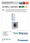
1
INSTALLATION - OPERATION - SERVICE MANUAL
TELECOM INVERTER
DC RANGE
EN
Outdoor packaged unit
i-MED
0031-0051-0071
INDEX
General warnings
3
Menu structure
17
Fundamental safety rules
3
Display screen
20
Identification
4
“LAN” Local Network
35
Receiving and handling the product
4
Interconnection between the units by shielded cable
36
Description of the appliance
5
Setting the addresses of the units (from 1 to 10)
and the user terminals (from 11 to 20)
36
38
Main functions
6
Operating Modes
6
Configuring the software for the recognition
and management of the units
Dimensional drawings
7
Special functions of the LAN network
39
General technical data
13
Serial board supervisory system
43
Operating limits
13
Alarm (Troubleshooting)
44
Installation
13
Troubleshooting
46
Electrical connections
14
Operating characteristics
47
Extended shutdown
47
Routine maintenance
47
Special maintenance
48
Disposal
48
Condensate drain
48
ELECTRICAL WIRING DIAGRAM
ON THE MACHINE
Control diagram
Controller
15
16
Liability disclaimer
This bulletin refers to standard executions, particularly as regards dimensions, weight, electric, hydraulic, aeraulic and refrigerant connections (where applicable). Contact Climaveneta Commercial Office for further drawings and schemes.
Climaveneta declines any liability deriving from use of the bulletin. This bulletin is the exclusive property of Climaveneta and
all forms of copy are prohibited. The data contained herein are subject to change without notice.
In some parts of this manual, the following symbols are used:
WARNING = for actions that require special care and
suitable preparation
PROHIBITED = for actions that absolutely MUST
2
i-MED EN
Specialist personnel
(electrician)
Person with in-depth knowledge
and experience such as to be
able to recognise risks and avoid
dangers that may derive from
electricity (IEV 826-09-01).
GENERAL WARNINGS
Incorrect installation, control and maintenance, improper use or installation by unqualified personnel
absolves the manufacturer from all liability,
whether contractual or otherwise, for damage to
people, animals or things. Only those applications
specifically indicated in this list are permitted.
Read this manual carefully. All work must be
carried out by qualified personnel in conformity
with legislation in force in the country concerned.
The warranty is void if the above instructions are
not respected and if the unit is started up for the
first time without the presence of personnel authorised by the Company (where specified in the supply
contract) who should draw up a “start-up report”.
The documentation supplied with the unit must
be consigned to the owner who should keep it carefully for future consultation.
When the items are consigned by the carrier,
check that the packaging and the unit are undamaged.
If damage, missing components or consignment errors are noted, indicate this on the delivery note.
A formal complaint should be sent via fax or registered post to the After Sales Service within eight
days from the date of receipt of the items.
All the operations involved in handling, installing,
starting up and testing the unit must be carried out
by qualified personnel.
Failure to observe this warning could cause serious
damage.
This appliance contains R410A refrigerant gas:
at the end of its working life, it should be taken to a
special collection centre; care should be taken to
avoid damage to the gas circuit and the finned coil.
Too low temperatures are harmful to health and
a useless waste of energy.
Avoid direct contact with the air flow for prolonged
periods.
These appliances have been designed for cooling and must be used for this purpose in applications compatible with their performance characteristics.
FUNDAMENTAL SAFETY RULES
When operating equipment involving the use of electricity
and refrigerant gas, a number of fundamental safety rules
must be observed, namely:
The unit must not be used by children or by unfit persons without suitable supervision.
Do not touch the unit with bare feet or with wet
or damp parts of the body.
Do not carry out cleaning operations without
first disconnecting the unit from the electricity supply by placing the mains switch in the “off” position.
Do not modify safety or control devices without authorisation and instructions from the manufacturer.
Do not pull, detach or twist the electrical cables
coming from the unit, even when disconnected from
the mains electricity supply.
Do not open doors or panels providing access to
the internal parts of the unit.
Do not dispose of, abandon or leave within
reach of children packaging materials (cardboard,
staples, plastic bags, etc) as they may represent a
hazard.
Do not allow refrigerant gas to leak into the atmosphere. Avoid contact with the refrigerant gas as
it is potentially hazardous.
Do not sit or stand on the appliance and/or
rest any type of object on top of it.
Do not spray or throw water directly on the
appliance.
Do not introduce pointed objects through the
air intake grills.
Respect safety distances between the unit and other
equipment or structures. Guarantee adequate space
for access to the unit for maintenance and/or service operations..
Power supply: the cross section of the electrical cables must be adequate for the power of the unit and
the power supply voltage must correspond with the
value indicated on the respective units. All units
must be earthed in conformity with legislation in
force in the country concerned. Electrical connections should be carried out as indicated in the instructions to guarantee correct operation of the
unit. Handle the unit with the utmost care to avoid
damage.
EN i-MED
3
IDENTIFICATION
The direct expansion units cab be identified by the:
Packaging label
Giving the data identifying the product.
Rating plate
Giving the technical and performance data of the unit.
If this is lost, ask the After Sales Service for a replacement.
The rating plate is fixed in a panel inside the electric board
Tampering with or the removal or absence of rating
plates or other means enabling the unit to be identified causes problems during installation and maintenance.
RECEIVING AND HANDLING THE PRODUCT
The direct expansion units are supplied accompanied by:
- instruction manual.
- warranty certificate.
- CE declaration.
These are contained in a plastic bag attached to the top of
the unit.
The instruction manual is an integral part of the
unit and should therefore be read and kept carefully.
Do not dispose of packaging materials in the environment or leave them within reach of children as
they may represent a hazard/source of pollution.
The unit should always be handled by qualified personnel
using equipment adequate for the weight of the unit.
4
i-MED EN
MED Inverter
DESCRIPTION OF THE APPLIANCE
The i-MED Inverter packaged units are suitable for the precision air-conditioning of mobile telephone shelters.
Direct expansion version, with inverter compressor, for
R410A. They are designed for indoor installation and fitted
with a freecooling damper to allow energy savings.
STRUCTURE
Panelling, base and internal structure made from epoxycoated metal, with stainless steel condensate collection
pan. The cover panels are internally coated with a thermal
and acoustic insulation, closed cell polyethylene foam extinguishing.
INVERTER COMPRESSORS
A hermetic compressor rotary scroll or DC. Brushless according to the size and full of the thermal protection at
high efficiency with control by INVERTERS electronic capabilities. This allows a good capacity with a partial loads,
which represent over 75% of normal operation time allowing an effective saving average total energy which can lead
to 50% compared to conventional technology type ON /
OFF. Fitted on rubber antivibration mounts and complete
charge of oil and oil separator to contain the effects of migration of gas charge and of the absence of lubrication
Crankcase.
POWER AND CONTROL ELECTRICAL PANEL
Power and control electrical panel constructed in accordance with IEC 204-1/EN60204-1, complete with compressor contactor and thermal solenoid switch and door lock
safety device.
AIR FILTERS
Filter Removable and washable made of acrylic material
self-extinguishing with efficiency class EU3 (standard) or
higher EU4.
EXCHANGE BATTERIES
Made using copper tubes and aluminium fins with a high
exchange surface area.
EVAPORATOR FAN
Radial fan with standard AC power supply or in alternative
48VDC power supply with electronic speed control.
CONDENSER FAN
Axial fans, statically and dynamically balanced.
Four or Six - pole electric motor with built-in thermal cutout. Housed in aerodynamic tubes with accident prevention grill. Device for operation according to the outside air
temperature: continuous fan rotation speed control via
pressure transducer.
REFRIGERANT CIRCUIT
Refrigerant circuit featuring the following components:
thermostatic valve, dewatering filter, liquid indicator, liquid
receiver, pressure switches for controlling the discharge
and suction pressure.
Unit supplied complete with refrigerant charge, factory
tested.
ELECTRIC HEATERS
Electric heater,s with double safety feature. Heating capacity 1,7 or 3,4 kW, depending on the size selected.
DIFFERENTIAL PRESSURE SWITCHES
Two differential air pressure switches for detecting faults
with the indoor fan or blocked filters.
PLC
The operation of the unit is managed by a PLC with a
graphic display.
OPTIONAL ACCESSORIES TO BE REQUESTED
WHEN ORDERING
- Humidity Sensor
- Function Dehumidification
- Clock Card
- Serial adapter for interfacing with external BMS
- Soundproof compressor jacket
- Shutter management and free cooling
- Air filter EU4 instead EU3 standard
- Air filter for fresh air intake
- Electric heater
- Power supply from UPS 48 VDC for evaporator fan and
damper free cooling if req.
For any further request please contact the office.
EN i-MED
5
MAIN FUNCTIONS
Main features
• Modulation of capacity
Using the new DC INVERTER SCROLL technology currently implemented in technological applications. The operation of the units is consequently automatically adapted
to the actual load conditions on site, providing the exact
amount of cooling required to maintain stable conditions
by modulating the capacity.
This also allows the units to be used in sites with varying
thermal loads.
• New R410A refrigerant
The use of the new high performance R410A refrigerant
with low atmospheric impact is in line with the strictest
environmental protection parameters.
• Modulation of the conditioned air flow-rate
The use of new high efficiency INVERTER EC technology
on the evaporator fan means that the i-MED can operate
at between 50% and 100% of the air flow-rate in freecooling operation, so as to minimise the power consumption
of the fan.
OPERATING MODES
Operation in freecooling or emergency mode
Operation in mechanical cooling mode
Outdoors air
Condenser air flow
Ricirculation air
Outdoors air
(Free Cooling)
Evaporator
air flow
6
i-MED EN
Evaporator air flow
88,5
EN i-MED
7
914
727
TOP VIEW
900
976
88,5
11
108
500
=
11
103,5
434
1698
1706
CONDENSATE DRAIN OUTPUT
875
BOTTOM VIEW
494
409
40
113,5
168,5
65
=
=
ELECTRICAL POWER
SUPPLY INPUT
730
500
939
77,5
=
500
N°10 SLOTS Ø8,5x20
500
1720
500
115
270
649
1735
744
215
31,5
40
420
39,5
REMOVABLE
PANEL
REMOVABLE
PANEL
REMOVABLE
PANEL
DIMENSIONAL DRAWINGS
i-MED 0031 UNDER
DIMENSIONAL DRAWINGS
i-MED 0031 UNDER - WALL DRILLING PATTERN
258
362
120
270
258
115
350
115
2400 *
270
1735
816
197 *
80 *
VIEW FROM INSIDE
THE SHELTER
760
62,5
80 *
153,5
468 *
497 *
29
30
40
* = HIPOTESIZED
8
i-MED EN
744
EN i-MED
495
600
11
124
128
42,5
605,5
1185,5
CONDENSATE DRAIN OUTPUT
915
BOTTOM VIEW
REMOVABLE
PANEL
90,5
11
510
49
1935
606
236
=
258
871,5
TOP VIEW
1016
939
N°10 SLOTS Ø8,5x20
500
979
258
=
18,5
15
155
550
550
550
115
24
114
19
649
1185,5
843
114
599
273
75,5
208,5
40
40
730
ELECTRICAL POWER
SUPPLY INPUT
270
824
200
77,5
49
18,5
DIMENSIONAL DRAWINGS
i-MED 0051 UNDER
9
1896
1906
1°
DIMENSIONAL DRAWINGS
i-MED 0051 UNDER - WALL DRILLING PATTERN
760
62,5
258
206
235 *
120
17
* = HIPOTESIZED
10
i-MED EN
80 *
1095 *
315 *
270
45
522
258
2400 *
270
1970
195 *
193,5
80 *
VIEW FROM INSIDE
THE SHELTER
744
EN i-MED
75
128
OUTPUT DRAIN CONDENSATE
1095
BOTTOM VIEW
188
685
1466
31,5
11
125,5
298
483,5
945
1196
TOP VIEW
1119,4
600
1159
298
500
18,5
500
125,5
19
208
200,5
128
REMOVABLE
PANEL
2237
35
1°
778
795
ELECTRICAL POWER
SUPPLY INPUT
N°12 SLOTS Ø8,5x20
200,5
300
1005
18,5
1866
785,7
71,7
1340
11
24 2
680
49
2279
238
500
500
163,5
2264
43
170
857,4
35
329
692,5
1462
1023
250
50
REMOVABLE
PANEL
DIMENSIONAL DRAWINGS
i-MED 0071 UNDER
11
DIMENSIONAL DRAWINGS
i-MED 0071 UNDER - WALL DRILLING PATTERN
VIEW FROM INSIDE
THE SHELTER
285
2279
+5
0
285
300
* = HIPOTESIZED
12
i-MED EN
80 *
15
80
113 *
165
0
-5
*
255
+5
0
80
1115
665
300
80 *
198
2400 *
800
8 *
198
775
GENERAL TECHNICAL DATA
Model
N. Circuit(s) / N. Compressor(s)
Refrigerant
Power supply V/Ph/Hz
COOLING CAPACITY
Total cooling capacity
Sensible cooling capacity
SHR
Compressor(s) power input
Evaporator air flow
Free-cooling air flow
Evaporator fan 48 V DC power input
Evaporator fan AC power input
Condenser max. air flow
Condenser fan AC power input
Sound pressure level (r=1m, Q=2)
ELECTRIC HEATER
Total heating capacity
DIMENSIONS & WEIGHT
(1)
(1)
(1)
(1)
OVER
UNDER
OVER
UNDER
OVER
UNDER
OVER
UNDER
Width
Depth (2)
Height
Net weight
kW
mc/h
mc/h
kW
kW
mc/h
kW
dB(A)
0031
1/1
R410A
230/1/50
MAX
MIN
9,53
4,34
7,22
4,34
0,76
1,00
2,37
0,75
1600
800
1600
800
0,36
0,11
0,23
0,17
2500
2500
0,16
0,16
52
0051
1/1
R410A
230/1/50
MAX
MIN
12,56
4,92
10,97
4,92
0,87
1,00
3,18
0,78
3200
1600
3200
1600
0,54
0,16
0,49
0,37
4000
4000
0,75
0,75
54
0071
1/1
R410A
400/3N/50
MAX
MIN
17,6
7,96
15,45
7,96
0,88
1,00
4,49
1,18
3900
1950
3900
1950
1,08
0,17
0,98
0,74
5900
5900
0,41
0,41
62
kW
1,7
3,4
3,4
mm
mm
mm
mm
mm
mm
kg
kg
n.a.
976
n.a.
500 (745)
n.a.
1735
n.a.
175
n.a.
1016
n.a.
600 (840)
n.a.
1935
n.a.
230
n.a.
1196
n.a.
780 (1025)
n.a.
2280
n.a.
310
kW
kW
(1) Ref. Conditions: Indoor=27°C, 45%UR Outdoor=35°C
(2) The dimension between ( ) considers rain hood dimension
OPERATING LIMITS
COOLING
Max
Min
DB: Dry bulb
Inside temp. DB/WB °C.
32/23,5
22/15,5
Outside temp. DB/WB °C
48/-25/-
WB: wet bulb
CALIBRATION OF PROTECTION DEVICES
High pressure switch
Low pressure switch
Opens (bar)
41,5 (+0-1,4)
3 (+-0,2)
Closed (bar)
33(+-2)
3,9 (+-0,3)
Reset
automatic
automatic
INSTALLATION
CHOICE OF INSTALLATION SITE
Before installing the unit, agree with the customer the site where
it will be installed, taking the following points into consideration:
- check that the fixing points are adequate to support the
weight of the unit;
- pay scrupulous respect to safety distances between the unit and
other equipment or structures (see functional clearances);
- install the unit with a minimum slope of 2 mm/m to guarantee condensate drainage
POSITIONING
Before handling the unit, check the capacity of the lift equipment used, respecting the instructions on the packaging.
To move the unit horizontally, make appropriate use of lift
trucks or similar, in the most appropriate way. The units are
supplied with the following accessories to simplify installation: vibration dampers, washers and fastening bolts for the
6 slots on the indoor unit. The distance between the fastening points on the ceiling are shown in the dimensioned
drawings on page 8.
CONDENSATE DRAIN CONNECTION
This operation must be carried out with particular care.
The unit is fitted with a condensate drain pan, and the connector on the rear of the unit is supplied with a plastic hose.
The following warnings must be observed for the connections:
1. Do not connect the drains from different units together.
2. Make sure the drain pipe has a slope of at least 2 cm/m
without obstructions or bottlenecks.
3. Fit a drain trap at least 30 mm below of the condensate pan.
4. Connect the condensate drain pipe to a rainwater
drainage system.
Do not connect to the sewage system as odours may be
sucked up if the water in the drain trap evaporates.
5. After connecting, check correct drainage of the condensate by pouring water into the pan.
6. Fill the drain trap with water in the tray by pouring water into the pan.
EN i-MED
13
ELECTRICAL CONNECTIONS
Voltage must be within a tolerance of ±10% of
the rated power supply voltage for the unit.. If these
parameters are not respected, contact the electricity supply company.
For electrical connections, use double insulation
cable in conformity with current legislation in the
country concerned.
Install, if possible near the unit, an appropriate
protection device to isolate the unit from the mains
supply. This should have a delayed characteristic
curve, contact opening of at least 3 mm and an adequate interruption and differential protection capacity.
If this device is not visible from the electrical
panel of the unit, it should be lockable
An efficient earth connection is obligatory.
Failure to earth the appliance absolves the manufacturer of all liability for damage.
In the case of three phase units, ensure the
phases are connected correctly.
Do not use refrigerant pipes to earth the unit.
ra dell’apparecchio. (Used the dedicated clamps)
The condensing units leave the factory fully wired. Installation is limited to connection to the mains electrical supply
and connection of the remote (ON/OFF) switch, operations that must be carried out by qualified personnel in
compliance with current legislation. For all electrical work,
refer to the electrical wiring diagrams in this manual.
You are also recommended to check that:
- The characteristics of the mains electricity supply are adequate for the power values indicated in the electrical
characteristics table below, also bearing in mind the possible use of other equipment at the same time.
Power to the unit must be turned on only after
installation work (refrigerant and electrical) has
been completed.
All electrical connections must be carried out
by qualified personnel in accordance with legislation
in force in the country concerned.
Respect instructions for connecting phase, neutral, earth conductors and the 48VDC polarities. The
power line should be fitted upstream with a suitable
device to protect against short-circuits and leakage to
earth, isolating the installation from other equipment.
ELECTRICAL PANEL
The electrical panel is located inside the unit at the top of the technical compartment where the various components of the refrigerant circuit are also to be found. To access the electrical panel, remove the front panel of the unit by undoing the self-tapping screws. To access the components in the electrical panel and the terminal boards, undo the four screws on the panel itself.
ELECTRICAL WIRING DIAGRAM ON THE MACHINE
Only for the machines with 48VDC power supply:
Must protect the 48 VDC power supply with a bipolar thermal Overload switch.
( The negative and even the positive)
POWER INPUT OF THE INDIVIDUAL COMPONENTS
COMPRESSOR
R410A
Model
0031
0051
0071
Power input
V/Ph/Hz
230/1/50
230/1/50
400/3N/50
EVAPORATOR FAN EVAPORATOR FAN
AC power input
48 V DC power input
F.L.I. F.L.A. L.R.A.
Nr.
kW
A
A
5,6 17,2
2,7
1
5,6 17,2
2,7
1
10,1 15,4
5,3
2
F.L.I.
kW
0,2
0,5
1,0
F.L.A.
A
1,0
2,4
4,7
TOTAL UNIT POWER INPUT i-MED R410A
COOLING ONLY,
COOLING ONLY,
with EVAPORATOR
with EVAPORAFAN AC power input
TOR FAN AC
and ELECTRIC
power input
HEATER
Power input
F.L.I. F.L.A. S.A
F.L.I.
F.L.A.
Model
V/Ph/Hz
kW
A
A
kW
A
0031
230/1/50
6,0 18,9 4,4
1,9
8,4
0051
230/1/50
6,8 23,0 8,5
3,9
17,2
0071
400/3N/50
11,5 21,9 11,8
4,4
19,5
14
i-MED EN
Nr.
1
1
2
F.L.I.
kW
0,4
0,5
1,1
F.L.A.
A
6,2
9,8
19,5
CONDENSER
FAN
Nr.
1
1
1
F.L.I.
kW
0,2
0,8
0,4
F.L.A.
A
0,7
3,4
1,8
ELECTRIC
HEATER
Nr.
1
2
2
F.L.I.
kW
1,7
3,4
3,4
F.L.A.
A
7,4
14,8
14,8
COOLING ONLY, 48V DC POWER SUPCOOLING ONLY,
with EVAPORATOR PLY (EVAP. FAN +
with EVAPORATOR
FAN 48 V DC
FREE COOLING
FAN 48V DC
power input and DAMPER + ELECTRIC
power input
ELECTRIC HEATER
BOARD)
F.L.I. F.L.A. S.A
F.L.I.
F.L.A.
F.L.I.
F.L.A.
kW
A
A
kW
A
kW
A
5,8 17,9 3,4
1,7
7,4
0,4
6,6
6,4 20,6 6,1
3,4
14,8
0,6
10,2
10,5 17,2 7,1
3,4
14,8
1,1
19,9
band
band
compressor
band
heater
band
compressor support unit
band
band
free cooling
support unit
band
fan. support unit
free cooling
fan
heater. support unit
low temperature alarm
band
max temperature alarm
band
high temperature alarm
CONTROL DIAGRAM
EN i-MED
15
CONTROLLER
Select alarms
Display
Programming
Up / Down
Exit
Confirm
Room T:
Display
The display shows the main values managed by the unit.
Alarms
Alarms are signalled by the light on the alarm button. Pressing the button displays the details of the causes of alarm.
To reset the alarms, press the alarm button again.
The controller saves up to 100 alarms.
Displaying and setting the unit parameters
Pressing the Prg button and entering the password accesses the menu for setting the parameters.
The operating parameters are sub-divided into the following levels:
• Level 1 (incorrect PSW): general unit status, alarms and graphs.
• Level 2 (user PSW required): USER MENU (0000).
• Level 3 (maintenance PSW required): MAINTENANCE MENU.
16
i-MED EN
DESCRIPTION OF THE AREAS SHOWN ON THE DISPLAY
FIRST PAGE
Menu structure: the pages in the main loop are scrolled using the UP and DOWN buttons.
If the clock is fitted and operating, the time and date are displayed.
If an analogue input is configured as the room temperature, this is displayed.
If an analogue input is configured as the room humidity, this is displayed.
AREA1: this displays the general status of the unit.
Unit off
Unit on and fan off
Unit on and fan on
Unit on and air-conditioner
1 fan active
Unit on and air-conditioner
2 fan active
Unit on and air-conditioner
1 and 2 fan active
AREA 2: this displays the detailed status of the unit.
Active alarm
Maintenance signal
Unit off from time bands
Unit off from keypad
Unit off from digital input
Unit off from time bands
Unit off from supervisor
Confort function active
Suction pressure limit at
compressor start
Suction - discharge delta P
at compressor start.
Free cooling disabled by
digital input
Unit in emergency mode
Unit in night mode
Unit on in LAN due to high
room temperature
Unit on in LAN due to low
room temperature
Unit awaiting LAN
Unit on in LAN
AREA 3: this displays an icon that, in the event of an alarm or a maintenance signal, indicates the type of alarm or the device
that requires maintenance respectively.
Configuration alarm
Fire/smoke/flood alarm
Fire/smoke alarm
Flood alarm
Outlet fan flow alarm
Outlet fan thermal overload
alarm
Blackout /incorrect phase
sequence alarm
Suction - discharge delta P
limit alarm
Envelope alarm (operation
outside the zone)
Thermostatic valve EEPROM
driver alarm
Inconsistent envelope alarm
Thermostatic valve not
closed at all
Thermostatic valve driver
temperature probe broken
or not connected
Low pressure alarm
Thermostatic valve driver
pressure probe broken or
not connected
Compressor alarm on
air-conditioner 1 and 2
Inverter alarm
tLAN driver thermostatic
valve alarm
Thermostatic valve motor
alarm
High pressure alarm from
digital input/analogue input
Compressor alarm on
air-conditioner 2
EN i-MED
17
Compressor alarm on
air-conditioner 1
Condenser fan thermal
overload alarm
Heater alarm
Blocked filter alarm
Damper alarm
EPROM alarm
Room temperature probe
alarm
Outside temperature
probe alarm
Outlet temperature
probe alarm
Maximum room temperature
alarm
Condensing pressure
probe alarm
High room temperature
alarm
High room humidity alarm
Low room humidity alarm
Room thermostat alarm
Auxiliary alarm
Clock alarm
Compressor maintenance
Outlet fan maintenance
Condenser fan maintenance
Compressor maintenance,
air-conditioner 1 and 2
Compressor maintenance,
air-conditioner 2
Compressor maintenance,
air-conditioner 1
Outlet fan maintenance
air-conditioner 1 and 2
Outlet fan maintenance,
air-conditioner 2
Outlet fan maintenance,
air-conditioner 1
Room humidity probe alarm
LAN disconnected alarm
Low room temperature
alarm
AREA 4: this displays the unit operating mode, heating or cooling, if the outlet fan temperature control function is enabled.
Unit in cooling mode
Unit in heating mode
Fan temperature control
not active
AREA 5: all the devices currently operating are displayed.
Compressor active
Air-conditioner
1 compressor active
Air-conditioner
2 compressor active
Air-conditioner 1 and 2
compressor active
Inverter-driven compressor with current activation ramp
AREA 6: all the devices currently operating are displayed.
Heater active
Air-conditioner 1 heater
active
Air-conditioner 2 heater
active.
Air-conditioner 1 and 2
heaters active
AREA 7: all the devices currently operating are displayed.
Dehumidification active
Emergency fan active
AREA 8: this displays the Unit LAN address.
Unit LAN address
AREA 9: if the ON/OFF from keypad option is enabled, this displays the corresponding icon.
Press ENTER for 5 seconds
to switch the unit off
18
i-MED EN
Press ENTER for 5 seconds
to switch the unit on
AREA 10: this displays the layout of the unit.
Packaged unit without
freecooling
Packaged unit with
freecooling closed, inside
air recirculation
Packaged unit with
freecooling open, full
outside air
Split unit without
freecooling
Split unit with freecooling
50%, inside/outside air
mixture
Split unit with freecooling
open, full outside air
Packaged unit with
freecooling 50%,
inside/outside air mixture
Split unit with freecooling
closed, inside air recirculation
SECOND PAGE
This displays the values of the analogue inputs enabled, identified by icons.
Room air temperature
Outlet air temperature
Room air humidity
Condensing pressure
Outside air temperature
THIRD PAGE
This shows the set point and band for all the devices enabled, identified by icons.
Outlet fan temperature
control in cooling
Outlet fan temperature
control in heating
Freecooling
Compressor
Heaters
Dehumidification
Compressor 1
Compressor 2
Heater 1
Heater 2
Emergency fan
FOURTH PAGE
This shows information relating to the software and hardware.
NOTE: the pages of the main loop is run with the UP or DOWN button
MANAGEMENT ELECTRONIC THERMOSTATIC VALVE
With thermostatic valve enabled displays a summary screen in the main loop:
Close to the suction temperature value, in the case of high suction
temperature protection, it appears an upwards flashing arrow.
In the bottom of the screen is displayed in case of alarm a concise description:
LOP protection
MOP protection
Error Temp Sensor
Error Sensor Press.
Step Motor Error
EEPROM error
Valve Not Closed
DRIVER NOT CONNECTED
EN i-MED
19
DISPLAY SCREENS
MAIN LOOP
FIRST PAGE
Press the
sequence.
button displays the following status screens in
SECOND PAGE
THIRD PAGE
1 unit controlled by the electrical panel controller
2 units controlled by the electrical panel controller
FOURTH PAGE
Press the
menu.
20
i-MED EN
button repeatedly to return to the main
PASSWORD ENTRY
Secondary loop
Pressing the
button accesses the password entry
page. Depending on the password entered, 3 loops of
screens may be enabled:
level 0 - incorrect password;
level 1 - user password 0000 (modifiable);
level 2 - maintenance password (modifiable);
Main screen
Press together
for 5 seconds
The language can be
changed
Press the Prg button
User password
0000 (modifiable)
LEVEL 1
Password not correct
LEVEL 0
Displays only:
Displays:
Maintenance password
Contact Climaveneta
LEVEL 2
Displays:
A Status
Digital 1
Digital 0
Analogue I
Analogue 0
Operating hours
pLAN network
A Stati
B Alarm log
B Alarm log
B Alarm log
C Graphs
C Graphs
C Graphs
D Clock
D Clock
E User
E User
Digital 1
Digital 0
Analogue I
Analogue 0
Operating hours
pLAN network
Fan
Freecooling
Compressor
Heater
Dehumidification
Alarms
pLAN network
Set password
A Status
Digital 1
Digital 0
Analogue I
Analogue 0
Operating hours
pLAN network
Fan
Freecooling
Compressor
Heater
Dehumidification
Alarms
pLAN network
Set password
F Maintenance
Analogue I
Operating hours
Manual alarms
Password
EN i-MED
21
LEVEL 0
A ALARM LOG
Digital 1
Digital O
Analogue 1
Analogue O
Operating Hours
pLAN
The inputs are already configured during production of the unit. Before changing any settings, contact the office.
Digital I
STATUS
Digital I
Digital O
Analogue I
Analogue O
Operating hours
pLAN
DIGITAL O
i-MED EN
To move to the
next row press
.
Screen displaying the status of the digital inputs
Screen displaying the status of the digital outputs
Screen displaying the status of the analogue inputs
Screen displaying the status of the analogue outputs
Screen displaying the device operating hours
Screen displaying the status of the pLAN network
Description
Not used
Room thermostat
External alarm
Fire/smoke alarm
Flood alarm
Flood and fire/smoke alarm
Remote ON/OFF
Remote ON impulse
Remote OFF impulse
Enable freecooling
Confort function
Low pressure switch
High pressure switch
Outlet fan thermal overload
Condenser fan thermal overload
Heater thermal overload
Outlet fan flow
Outlet fan filters blocked
230/400Vac power connected and incorrect phase sequence
Air-conditioner 1 alarm
Air-conditioner 2 alarm
Air-conditioner 1 compressor on
Air-conditioner 2 compressor on
Inverter allarm
Possible configurations of the digital outputs
Value
0
1
2
3
4
5
6
7
8
9
10
11
12
13
14
15
16
17
18
19
20
21
22
23
24
25
26
27
28
A2
Confirm by
pressing .
Possible configurations of the digital inputs
Value
0
1
2
3
4
5
6
7
8
9
10
11
12
13
14
15
16
17
18
19
20
21
22
23
A1
22
To change the To change the
value press
. value press
and .
Description
Not used
allarm 1
allarm 2
allarm 3
allarm 4
allarm 5
allarm 6
allarm 7
FC fan
Unit status
Compressor status
Fan discharge status
FC status
Heater status
FC fan status
FC open
FC closed
Discharge fan
Condenser fan
Compressor
Dehumidification
Heater
Fan discharge 1
Fan discharge 2
Compressor 1
Compressor 2
Heater 1
Heater 2
Inv. Compressor
ANALOGUE I
Pressure
Humidity
Room T.
Outlet T.
Outside T.
A3
ANALOGUE O
Open FC
Outlet fan
Cond. fan
Free cooling fan
A4
Operating hours
A5
This screen is displayed in systems with:
1 unit controlled by one PLC
A6
This screen is displayed in systems with:
2 units controlled by the same PLC
A7
This screen is displayed in systems with:
2 units controlled by the same PLC
pLAN network
A8
pLAN network status screen
This screen, only active if the LAN is enabled, displays the status of the units connected in the pLAN network.
Addresses 1 to 10 are used for controllers, addresses 11 to 20
for private terminals, and address 32 for the shared terminal.
EN i-MED
23
B ALARM LOG
List of alarms
ALARM LOG screen
In this screen this displays the alarm log.
A maximum of 100 events can be saved, once having
reached the one hundredth alarm, i.e. the last space
available in the memory, the next alarm is saved
over the oldest alarm (001), which is deleted, and so
on for subsequent.
To scroll the list of logged alarms press / .
Reset memory
AC 1 fan hour threshold
AC 2 fan hour threshold
AC 1 comp. hour threshold
AC 2 comp. hour threshold
Fan hour threshold
Compressor hour threshold
Clock
Auxiliary
Room thermostat
Low humidity
High humidity
Low temperature
High temperature
Maximum temperature
pLAN network
Pressure probe
Humidity probe
Outlet temp. probe
Outside temp. probe
Room temp. probe
EPROM
Freecooling damper
Dirty filters
Heater thermal overload
Fan thermal overload
AC 1 compressor
AC 2 compressor
Low pressure
High pressure A (Analogue)
High pressure D (Digital)
No power
Fan thermal overload
No flow
Flood
Fire/smoke
Flood Fire/smoke
DA CFG (Digital/Analogue configuration)
AO CFG (Analogue Output configuration)
DO CFG (Digital Output configuration)
AI CFG (Analogue Input configuration)
DI CFG (Digital Input configuration)
Reset log
Temperature probe
Pressure probe
Step Motor
EEPROM
Valve not closed
tLAN
Out of envelope
Inconsistent envelope alarm
Inverter compressor
Suction – discharge delta P
C GRAPHS
C1
GRAPHS screens
The first screen displays a graph showing the trend in room air
temperature, the screen is enabled if an analogue input is configured as the room air temperature reading.
C2
Note: The second screen displays the logged values (temperature only)
24
i-MED EN
LEVEL 1
•
•
•
•
Status
Alarm log
Graphs
Clock
To change the To change the
value press
. value press
and .
Confirm by
pressing .
To move to the
next row press
.
D CLOCK
CLOCK screen
This screen is used to set the time and date.
E USER
USER
Fan
Fan
Freecooling
Compressor
Heater
Dehumidification
Alarms
pLAN network
Configuration
Password
The set points for all the resources can be set in the
USER level.
Screens for setting the main fan operating
parameters
Freecooling
Screens for setting the freecooling operating
parameters
Compressor
Screen for setting the compressor operating
parameters
Heater
Screen for setting the heater operating parameters
Dehumidification Screen for setting the dehumidification operating
parameters
Alarms
Screens for setting the alarm parameters
pLAN network Screen for setting the pLAN network parameters
Configuration
Screen for setting the configuration parameters
Password
Screen for setting the level 1 password
The loops of screens are displayed if the corresponding devices are enabled.
Fan
E1
Fan digital control
Temperature control: with temperature control the fan switches on and off depending on the value of the heating and cooling set point.
YES / NO
Cooling set point:
used to set the cooling set point temperature.
Cooling band:
used to set the band in cooling mode.
Heating set point:
used to set the heating set point temperature.
Heating band:
used to set the band in heating mode.
P+I control:
used to choose between proportional or proportional-integral control (in the latter control depends on the time set).
Integral time:
used to set the time for proportional-integral control.
E2
Fan analogue control
Temperature control: with temperature control the fan switches on and off depending on the value of the heating and cooling set point.
YES / NO
Modulation:
enables modulating operation of the fan.YES / NO
Cooling set point:
used to set the cooling set point temperature.
Cooling band:
used to set the band in cooling mode.
Cooling cut-off:
used to set the temperature in the shut-down phase in cooling mode.
Heating set point:
used to set the heating set point temperature.
Heating band:
used to set the band in heating mode.
Heating cut-off:
used to set the temperature in the shut-down phase in heating mode.
EN i-MED
25
E3
Fan non-modulating analogue control
If selecting modulating NO this screen is displayed with the
fixed parameters.
E4
Fan modulating analogue control
If selecting modulating YES this screen is displayed with the values that can be set for the fan.
Minimum cooling:
Maximum cooling:
Minimum heating:
Maximum heating:
Dehumidification:
Start-up time:
P+I control:
Integral time:
used to set the minimum fan speed in cooling mode.
used to set the maximum fan speed in cooling mode.
used to set the minimum fan speed in heating mode.
used to set the maximum fan speed in heating mode.
enables the dehumidification function.
used to set the delay in starting the fan.
used to choose between proportional or proportional-integral control (in the latter control depends on the time set).
used to set the time for proportional-integral control.
E5
Sniffing:
Fan ON:
Fan OFF:
allows of switch on / turn off the fan per a time determined.
used to set the fan on time.
used to set the fan off time.
E6
This screen is displayed in systems with:
2 units controlled by the controller
Rotation hours:
Rotation test:
used to set the hours for master and slave rotation.
used to set the minutes to test the operation of master /
slave rotation
Freecooling
Page 1
E7
Set point:
Band:
Minimum:
Maximum:
P+I control:
Integral time:
FC Modulating:
used to set the temperature per the opening of the
freecooling damper.
used to set the band.
used to set the minimum damper opening.
used to set the maximum damper opening.
used to choose between proportional or proportional-integral control (in the latter control depends on the time set).
used to set the time for proportional-integral control
used to set the damper in modulating mode.YES / NO
Page 2
E8
In/out delta:
used to set the delta between the inside temperature and
the outside temperature for opening the freecooling damper
DT band:
used to set the band for opening the freecooling damper.
FC with compressor: allows simultaneous operation of freecooling and the compressor. YES / NO
Delay:
used to set a delay for opening the freecooling damper.
Outlet limit:
enables a limit to ensure too much cool air is not introduced into the site. YES / NO
Minimum temp.:
used to set the minimum inlet temperature via the freecooling damper.
Band:
used to set the band for the minimum temp.
26
i-MED EN
Page 3
E9
Emergency mode:
Set point:
Band:
Delta T:
DT band:
FC with compressor:
Compressor alarm:
enables the freecooling damper in the event of emergencies. YES / NO
used to set the temperature for activating emergency
mode.
used to set the set point band.
used to set the temperature delta in emergency mode.
used to set the temperature delta band in emergency
mode.
allows simultaneous operation of freecooling and the compressor in emergency mode. YES / NO
allows freecooling operation if the compressor alarm is activated. YES / NO
Compressor
This screen is displayed in systems with:
1 unit controlled by one PLC
E10
Set point:
Band:
used to set the set point for activating the compressor.
used to set the band for activating the compressor.
This screen is displayed in systems with:
2 units controlled by the same PLC
E11
Set point AC 1:
Band:
Set point AC 2:
Band:
used to set the set point for activating the compressor relating to the 1st air-conditioner.
used to set the band of start-up of the compressor.
used to set the set point for activating the compressor relating to the 2nd air-conditioner.
used to set the band for activating the compressor.
Heater
This screen is displayed in systems with:
1 unit controlled by one PLC
E12
Set point AC 1:
Band:
used to set the set point for activating the heater.
used to set the band for activating the heater.
This screen is displayed in systems with:
2 units controlled by the same PLC
E13
Set point AC 1:
Band:
Set point AC 2:
Band:
used to set the set point for activating the heater relating to
the 1st air-conditioner.
used to set the band for activating the heater.
used to set the set point for activating the heater relating to
the 2nd air-conditioner.
used to set the band for activating the heater.
Dehumidification
E14
Enable:
Set point:
Band:
Temp. limit:
Temp. band:
Enable FC limit:
FC limit:
FC limit band:
enables the dehumidification function. YES / NO
used to set the set point for operation of the dehumidifier.
used to set the band for operation of the dehumidifier.
used to set the minimum temperature limit, for operation of
the dehumidifier.
used to set the band for the operating temperature limit.
enables the humidity limit for activating the freecooling
damper. YES / NO
used to set the humidity limit for activating freecooling.
used to set the humidity limit band for activating freecooling.
EN i-MED
27
Alarms
Used to set the alarm set points.
The set points are pre-set in the factory.
E15
E16
This screen is displayed in systems with:
1 unit controlled by one PLC
E17
Page 1
Used to configure the alarm signals (from 1 to 7, depending on
the controller and configuration).
The user can select which alarms activate the alarm signal output.
E18
Page 2
E19
Page 3
The state NC / NO allows you to configure the polarity of the
contact alarm.
E20
This screen is displayed in systems with:
2 units controlled by one PLC.
Page 1
Each alarm can be configured to perform an action on the system.
0 No action
1 Add unit to network.
2 Switch unit off and switch on another in the network.
3 Switch off all the units in the network
28
i-MED EN
E21
Page 2
E22
Page 3
Note: When an alarm is activated, the main screen shows the alarm symbol (page 14-15) in area 3; pressing the
ALARM button opens the alarm display screens and the audible alarm sounds; if more than one alarm is active, these
can be scrolled using the UP and DOWN buttons. Pressing the ALARM button on one of the alarm display screens resets all the alarms; if the alarms are still active, the audible alarm sounds again.
EN i-MED
29
pLAN network
The network can have a maximum of 10 units and 11 terminals, one of which shared. Unit operation in the LAN network
is configured on unit 01.
Page 1
E23
Enable LAN:
enables the LAN function. YES / NO
No. of units in LAN: used to set how many units are connected to the LAN.
Average temperature: this function allows temperature control on the individual
units using the average temperature measured by the active
units connected to the pLAN. YES / NO
No. of units in STBY: sets how many units are in Standby.
Rotation hours:
this function is used to balance the operating hours of the units
connected in a pLAN network. Rotation is performed based on
the set time, expressed in hours, activating the unit with the
lowest address first. A maximum of 2 units can be set in standby
if there are more than 4 units connected in the pLAN network.
runs the test to verify the exact operation of the rotation function.
Rotation test:
Page 2
E24
Used to set the pLAN Support set points.
Page 3
E25
Each alarm can be configured to perform an action on the LAN.
0. No action
1. Add unit to network.
2. Switch unit off and switch on another in the network.
3. Switch off all the units in the network.
E26
Page 4
E27
Page 5
See the paragraph on “LAN - local network”
30
i-MED EN
Configuration
Page 1
E28
ON/ OFF keypad: enabling this function means the unit can be switched on and off
by pressing the ENTER button for 5 seconds on the main
screen. YES / NO
Time bands:
enabling this function means the unit can be switched on and off
based on time bands.
Start:
used to set the time the unit starts operating.
End:
used to set the time the unit stops operating.
Supervision:
enabling this function allows the unit to be managed by a supervisor, fitting an optional board.
Address:
used to set the address for the supervisor.
Speed:
selects the communication baud rate.
Protocol:
selects the communication protocol.
Modbus/Carel/Lon
Page 2
E29
Night function:
by enabling this function, in specific time bands a different set
point can be set for the fan and the compressor, plus a reduced outlet fan speed. YES / NO
Start:
used to set the Night function start time.
End:
used to set the Night function end time.
Compressor set:
used to set the compressor set point for the night function.
Out fan reduction: used to reduce the outlet fan speed for the night function.
Cooling set point: sed to set the cooling set point for the night function.
Heating set point:
used to set the heating set point for the night function.
Cond. fan reduction: used to reduce the condenser fan speed for the night function.
Password
E30
Screen for setting the level 1 password
EN i-MED
31
LEVEL 2
•
•
•
•
•
Status
Alarm log
Graphs
Clock
User
To change the To change the
value press
. value press
and .
Confirm by
pressing .
To move to the
next row press
.
F MAINTENANCE
MAINTENANCE
I Digital
Digital Screens for calibrating the analogue imputs
0 Digital
Digital Screens for calibrating the analogue outputs
I Analogue
Analogic Screens for calibrating the analogue imputs
0 Analogue
Analogic Screens for calibrating the analogue outputs
Operating hours Reset Screen, for works hours
Alarms
Setting Screen, for reset alarms and reset storic
Manual
Activation Screen, for manual mode and simulator
probes
Password
Setting Screen, for password 2° level
The loops of screens are displayed if the corresponding devices are
enabled.
Digital
Page 1
Calibration of digital imputs
F1
It allows to correct the reading of the probe by inserting an
offset
Page 2
Calibration of digital outputs
F2
Analogue
Pag. 1
Calibration of analogue imputs
F3
It allows to correct the reading of the probe by inserting an
offset
Page 2
Calibration of analogue outputs
F4
Entering a value positive or negative in the Cal. parameter, the
value of the probe increases or decreases
32
i-MED EN
Operating hours
This screen is displayed in systems with
1 unit controlled by one PLC
F5
Used the reset the various operating hours YES / NO.
This screen is displayed in systems with:
2 units controlled by the same PLC
F6
Page 1
Used the reset the various operating hours YES / NO.
Page 2
F7
Alarms
F8
Each alarm can be set as manual or automatic reset; the
MAINTENANCE LOOP, ALARM screens feature the corresponding parameters.
For alarms with automatic reset, the display on the main
screen disappears when the alarm is not longer active, however the alarm display screens and buzzer remain active until
the alarm is reset by pressing the ALARM button.
F9
F10
EN i-MED
33
Manual
This screen is displayed in systems with:
1 unit controlled by one PLC
F11
In manual mode, the devices can be activated independently of
the control functions, while the safety features are still active.
Manual mode can last a maximum of 30 minutes.
This screen is displayed in systems with:
2 units controlled by the same PLC
F12
Page 1
In manual mode, the devices can be activated independently of
the control functions, while the safety features are still active.
Manual mode can last a maximum of 30 minutes.
Page 2
F13
Password
Screen for setting the level 2 password
F12
NOTE:
34
LANGUAGE SETTING
Press both bottom at the same time, then select your own language
TO CHANGE THE DISPLAY
CONTRAST
Press at the same time
i-MED EN
To adjust (up or down)
the contrast
"LAN" - LOCAL NETWORK (E22- E23 - E24 DISPLAY SCREENS)
MAIN FUNCTIONS OF THE LAN
The connection of the units (that is, the PCO boards fitted
on each unit) in the pLAN network allows the following
functions to be performed:
• balance the operating hours between the air-conditioners
by rotation of the standby unit.
• start the standby unit if the other unit shuts down due to
a serious alarm or blackout
• start the standby unit to provide for excessive thermal
load.
• control up to 10 air-conditioners from just one user terminal (shared user terminal)
• operation of all the air-conditioners based on the average
of the temperature and humidity values read by the
probes on the air-conditioners that are operating at that
moment
1. The local network connection is used to manage the
operation of a series of air-conditioners operating inside
the same environment,
2. The number of units that can be connected is 10 MAX.
3. The maximum extension of the network connections is
500 metres.
4. All the units connected in the network must have the
same version of the program installed in the flash
memory on the board.
5. A terminal can be configured as "private" or "shared":
- a private terminal can display the operating status
only of the unit it is connected to via telephone cable
- a shared terminal can display the operating status of
all the units connected in the network.
6. Each board can “talk” to a maximum of 3 terminals; in
common applications, generally no more than two are
used: one fitted on the unit and another optional remote
terminal.
The priority on the terminal is always the display of the
alarms, even if when the alarm is activated the terminal is
displaying the parameters from another unit.
7. To be able to communicate over a local network, the
units must be configured so as to be able to send the
other units the required information for correct operation.
In this regard, the first step involves assigning a progressive number to the different units (1, 2, 3,…10) and then
correctly setting the addresses of the various terminals
and LAN boards, and making the electrical connections,
step-by-step, as described in the following paragraphs.
EN i-MED
35
1) INTERCONNECTION BETWEEN THE UNITS BY SHIELDED CABLE
In order to realize a LAN (Local Area Network) between the units,
of the units (on the El.Panel) and not on the main board directly.
it is required that installers provide to link together all units with a
Connectors RX/TX+, RX/TX-, & GND are in different
dedicated cable. The cable is not supplied by CLIMAVENETA. AWG
positions/Clamps based on the unit type and size: consequenly
24 cables with two twisted pairs plus shield, such as the Belden
please always refer to the electrical diagram inside the units where
8723 or 8102, and AWG 24 cables with three twisted pairs plus
such connectors are clearly indicated.
shield, Belden 8103 or similar, are recommended.
Remember that connection between 3 connectors RX/TX+,
The electrical connections must be completed when the units are
RX/TX-, & GND has to be similar among the units: the shield has to
off and disconnected from the power supply following the below re-
be connected to the earth connector only in 1 unit.
ported schema.
Refer to the below unit for the unit interconnection. (for the right
Connections must be provided directly on the main terminal block
clamps refer to the el. Diagram on the unit).
LAN CONNECTION BETWEEN 2 OR MORE UNITS
Cable connected to the earth
on the unit
Shielded cable for units interconnection. (under INSTALLER charge)
RX/TXRX/TX+
GND
UNIT Nr. 1
RX/TXRX/TX+
GND
UNIT Nr. .......
2) SETTING THE ADDRESSES OF THE UNITS (FROM 1 TO 10) AND THE USER
TERMINALS (FROM 11 TO 20)
CONFIGURING THE NETWORK
When it has been realized the electrical interconnection as reported on phase 1) it is required to switch to phase 2) for the
address configuration for:
A) units, addresses from 1 to 11
B) user terminal/Display, addresses from 11 to 20
Remember that standard confirguration from factory is the following:
Address 1 for the unit
Address 11 for the user terminal/Display
Remember that the MAX amount of units per LAN line are 10
(with max 2 in stad-by).
Right confirguration and addresses for units and user
terminals/Display are reported on the following resuming table.
TABLE OF TERMINAL ADDRESSES AND LAN BOARD ADDRESSES
LAN Board Address
1
2
3
4
5
6
7
8
9
10
LAN Board Address
-
36
i-MED EN
Terminal address / Display
11
12
13
14
15
16
17
18
19
20
Terminal address / Display
32 (remote / shared)
A) UNITS ADDRESSES (FROM 1 TO 10)
Right units configuration is foundamental for the network in order
to recognize all units connected.
Same addreessing for 2 or more units in the same LAN network is
not allowed: in such casethe following alarm screen will appear .
NO LINK
• To set the terminal address (display address setting), press the
ENTER button once: the cursor will move to the address field
(n°11).
• Use the UP and DOWN buttons to select the "0" (zero) value
and confirm by pressing ENTER again.
If the value selected is different from the one saved previously,
the following screen will be displayed and the new value will be
saved to the permanent memory on the display.
Display address
changed
Units addressing can be done only from user terminal/display.
Units addressing can be done only if the user terminal/display is previusly setted with "0" (zero) address.
A1) PROCEDURE TO ADDRESS THE USER
TERMIAL/DISPLAY AT "0" ZERO
It is possible to set the user terminal/display address only after
giving it a power supply through the telephone cable on its rear
side (connected to the main board).
To enter configuration mode press simultaneusly following buttons UP, ENTER, DOWN for 5 sec.; the following screen will appear with cursor blinking on the top -left side.
Display address
setting.............................:
I/O Board address:
11
01
B) USER TERMINAL/DISPLAY ADDRESSING FROM 11
TO 20
At this point unit n°1 has to be connected with user terminal/display 11, unit n°2 has to be connected with user terminal/display 12
etc.…………...unit n°10 has to be connected with user
terminal/display 20 (look the following table)
To enter configuration mode press simultaneusly following buttons UP, ENTER, DOWN for 5 sec.; the following screen will appear with cursor blinking on the top -left side.
Display address
setting.............................:
I/O Board address:
00
01
A2) PROCEDURE TO ADDRESS THE UNITS (ADDRESSES FROM 1 TO 10)
Once the terminal address is set to "0" (zero), disconnect power
supply from the board and then power it up again while at the
same time holding the ALARM and UP buttons on the user terminal: wait until the following screen is displayed.
pLan address:
UP:
DOWN:
ENTER:
1
increase
decrease
save & exit
Release the buttons and set the correct address as per the table
shown above, from 1 to 10. Same addreessing for 2 or more units
or user terminals/display in the same LAN network is not allowed.
Set the right value. Remember to set units addresses progressively from 1 to 10 within the sme LAN line.
TABLE OF TERMINAL ADDRESSES AND LAN BOARD ADDRESSES
LAN Board Address
1
2
3
4
5
6
7
8
9
10
LAN Board Address
-
Terminal address / Display
11
12
13
14
15
16
17
18
19
20
Terminal address / Display
32 (remote / shared)
• To modify the terminal address (display address setting), press
the ENTER button once: the cursor will move to the address
field (n°00).
• Use the UP and DOWN buttons to select the right value reported on the table
If the value selected is different from the one saved previously,
the following screen will be displayed and the new value will be
saved to the permanent memory on the display.
Display address
changed
EN i-MED
37
3) CONFIGURING THE SOFTWARE FOR UNIT RECOGNITION AND MANAGEMENT
All the settings corresponding to the LAN can be made starting from the settings menu and accessing (second row) the branch of LAN/serial configuration screens. All the parameters can be set on the MASTER unit only (that is, the unit with address 1), which automatically sends
any changes to all the other units in the network.
La rete può essere costituita da un massimo di 10 unità e 11
terminali di cui uno condiviso. La configurazione del funzionamento delle unità in rete LAN avviene nella unità 01.
Page 1
E23
Enable LAN:
enables the LAN function.YES / NO
No. of units in LAN: used to set how many units are connected to the LAN.
Average temperature: this function allows temperature control on the individual
units using the average temperature measured by the active
units connected to the pLAN. YES / NO
No. of units in STBY: sets how many units are in Standby.
Rotation hours:
this function is used to balance the operating hours of the units
connected in a pLAN network. Rotation is performed based on
the set time, expressed in hours, activating the unit with the lowest address first. A maximum of 2 units can be set in standby if
there are more than 4 units connected in the pLAN network.
Rotation test:
runs the test to verify the exact operation of the rotation
function.
Page 2
E24
Used to set the pLAN Support set points.
<z
E25
Each alarm can be configured to perform an action on the LAN.
0. No action
1. Add unit to network.
2. Switch unit off and switch on another in the network.
3. Switch off all the units in the network.
E26
Page 4
E27
Page 5
See the paragraph on “LAN - local network”
NB: For each pCO controller can be connected to two user terminals one private and one shared, the user terminal can be directly connected to the card pCO on the connector RJ12 phone or through a derivative. In the network there can be at most one shared terminal
with address 32. The shared terminal is able to connect to all the controllers present in pCO network plans, to move from one address to
another, simply press the keys simultaneously ESC + ALARM. In any mask of view, you can see which is the address of a controller connected by simultaneously pressing the keys UP + DOWN for 5 seconds.
38
i-MED EN
FUNCTIONS OF THE LAN NETWORK
If the LAN is enabled, allows the management of various functions.
AVERAGE TEMPERATURE
This feature allows temperature control of individual units using the average of the temperatures measured by the active units connected to
the pLAN.
ROTATION
This feature allows the balance of the hours of operation of the units connected to the pLAN. The rotation is based on the set time expressed in hours, first activates the unit with the lowest address. They can be set to a maximum of 2 units on stand-by if the units connected
to the pLAN are 4. Activating the function of "rotational test" the unit of measurement of time for rotation is given in minutes.
ACTIVATION UNIT FOR SUPPORT OF THE TEMPERATURE
If this function is active allows the activation of the unit in stand-by for exceeding temperature limits, the reference temperature is the most
cold or less hot, between temperatures measured between the active units, or the average of the relative temperature if is activated the
function. Activation unit in stand-by is a function of set point and the band as specified in the following chart:
State
ON
2° unit
stand by
OFF
ON
2° unit
stand by
OFF
Hot band
1/2 hot band
hot set point
cold set point
1/2 cold band
cold band
Tamb. °C
The first unit will be called in support of the set point of activation resources varied by adding / subtracting the parameter deviation set
point cold / hot, the second unit will have changed the set point for twice.
The following graph shows the deviation of the compressor set point activation for 2 units on stand-by:
State
ON
2° unit in support
OFF
ON
1° unit in support
OFF
ON
Unit ON
OFF
Tamb. °C
Hot band
band
set point +
deviation Set
band
set point +
2° deviation Set
band
EN i-MED
39
ACTIVATION UNIT FOR THE ALARM
Each alarm can be configured to have an effect on the LAN:
0. No effect;
1. Add a unit in the network;
2. Turn off unit and turn on another drive on the network;
3. Turn all the units in the network.
LAN PARAMETER
USER LOOP of LAN Network
Parameter
abil_lan
n_unita_lan
abil_media_temp
n_standby_lan
ore_rotazione
test_lan
abil_supporto_lan
set_point_lan_freddo
banda_lan_freddo
scost_1_freddo
set_point_lan_caldo
banda_lan_caldo
scost_1_caldo
lan_al_01
…
lan_al_43
40
i-MED EN
Description
Enabling functions pLAN
Number of units in the pLAN Network
Enabling average temperatures pLAN
Number of units on stand-by
Rotation time
Enabling rotation test
Enabling support for pLAN temperature
Set point activation units in cold LAN
Activation band for units in cold LAN
Deviation set point cold
Set point activation units in hot LAN
Activation band for units in hot LAN
Deviation set point Hot
Alarm AL01, effect in LAN
…
Alarm AL43, effect in LAN
UM
flag
num
flag
num
ore
flag
flag
°C/10
°C/10
°C/10
°C/10
°C/10
°C/10
num
num
num
Min
0
2
0
0
1
0
0
0
0
0
-999
0
0
0
0
0
Max
1
10
1
2
24
1
1
999
999
999
999
999
999
3
3
3
Default
0
2
0
1
24
0
0
210
30
40
50
20
30
0
0
0
CONNECTION TO THE REMOTE TERMINAL FROM THE BOARD
This configuration requires:
1. the use of two 'T' shunts: one fitted on the unit and one near
the remote terminal;
2. the use of the 3x2 shielded cable, so that the power to the remote terminal is also supplied by the board on unit 1, connected using the 'T' shunt;
3. near the terminal, insert the ferrite to reduce any electromagnetic disturbance.
Remote terminal no. 32
J17
Board no. 1
J11
Three-pair cable
pairs with 6-pin
telephone connector.
Three-pair shielded cable: 3 x 2 x
AWG 24 (six lead cable with
shield and twisted pairs, AWG24,
resistance < 80ohm/M). Remote
terminal no. 32 Board no. 1 Term.
Term. no. 11
Maximum distance between terminal/board: 200 m
Connections for the 2 x 2 x AWG 24 CABLE
(for connecting the remote terminal: without transferring
the power supply)
terminal
0
1
2
3
4
5
6
function
cable connections
Earth
+ VRL ≈ 30Vcc
Gnd
Rx/Tx Rx/Tx +
Gnd
+ VRL ≈ 30Vcc
shield
First pair
Second pair
Second pair
First pair
FERRITE
EN i-MED
41
ELECTRICAL CONNECTIONS
The electrical connections must be completed when the units are
If both the jumpers are installed between 2 and 3 the flow of cur-
off and disconnected from the power supply. The network can
rent is interrupted between the connectors separated by the
have different configurations, according to the maximum distance
dashed line.
of the connections between the boards and the remote terminal;
If power is required on all the connectors, both the jumpers must
for the connections between the remote terminal and the main
be installed between 1 and 2.
board, a 'T' shunt may be required, as shown in the drawing.
Terminal 0 is an auxiliary terminal and can be used to earth the
shield of the cable; the 'T' shunt must in any case be connected to
a metallic part of the unit that is already earthed.
Terminals
MAXIMUM DISTANCE BETWEEN THE TERMINAL
AND THE BOARD
A
B
C
1 For local terminals the connection to the main board is already
made using a 3-pair cable and 6-pin telephone connector. The
length of this cable generally does not exceed 3 metres.
123 123
2 The remote terminals can be connected to the main board using the type of telephone cable described in point 1, with a
pin-strip
maximum distance of 50 metres.
3 For greater distances, up to a maximum of 200 metres, a shield-
terminal
function
0
1
2
3
4
5
6
Earth (shield)
+VRL ≈ 30Vcc
Gnd
Rx/TxRx/Tx+
Gnd
+VRL ≈ 30Vcc
42
i-MED EN
ed cable must be used (six lead cable with shield and twisted
pairs, AWG24, resistance < 80 ohm/M). The cable may have 3
or 2 pairs, depending on whether the power needs to be supplied to the terminals. The cable is not supplied by CLIMAVENETA.
AWG 24 cables with two twisted pairs plus shield, such as the
Belden 8723 or 8102, and AWG 24 cables with three twisted
pairs plus shield, Belden 8103 or similar, are recommended.
SERIAL BOARDS AND SUPERVISORY SYSTEM
NB: this part is not intended to go into detail on the various ver-
The interfacing and sharing of the control variables with such sys-
sions and options available in the CLIMAVENETA range as regards
tems can be performed using serial boards/interfaces that are
supervisory systems, a topic that will be dealt with in a special man-
compatible with the BMS that the variables should be exchanged
ual. Rather, the purpose is to provide a rapid indication of the oper-
with.
ations to be performed on the unit software by setting parameters
Consequently, the various OPTIONS that can be ordered when
from the user terminal so as to activate the database on the con-
purchasing the unit (and can also be supplied subsequently) in-
troller.
clude the following serial interface boards:
Therefore below is a short list of the operations to be carried
out for the management of a serial interface board, in particular:
- CLOCK
board used for identifying alarm events by
1) Options and serial boards currently available
time. The clock board MUST NOT be instal
2) Installation
led in the same SLOT as the serial boards
3) Configuration of the software from the terminal
4) Configuration / Physical development of the serial net-
listed below
- RS485
work
for dialogue with protocols: CAREL and
MODBUS
- RS232
for dialogue with protocol RS232
1) Options and serial boards currently available
- BACNET
for dialogue with protocol: BACNET
Currently CLIMAVENETA offers the market a series of serial in-
- ETHERNET
for dialogue with protocols: SNMP and
terfaces that allow the ACCURATE precision air-conditioners to
share their control variables with local or remote BMS (Building
TCP/IP- LON
for dialogue with protocol: LON
Management Systems), both proprietary systems and those more
commonly found on the market today.
CLOCK BOARD
RS485 - MODBUS SERIAL CARD
ETHERNET / BACNET SERIAL CARD
RS232 SERIAL CARD
LON SERIAL CARD
EN i-MED
43
ALARMS (TROUBLESHOOTING)
Alarm
Description
Configuration alarm
Solution
No user action possible.
Contact Service
Check status on site.
Devices switched off
ignal only
Stops operation of the unit
Outlet fan flow alarm.
Check status on site.
Reset if possible.
Check status on site.
Reset if possible.
Check operation on site.
Outlet fan thermal overload alarm.
Check operation on site.
Stops operation of the unit
Blackout/incorrect phase sequence
alarm.
Suction – discharge delta P limit alarm
Check phase sequence and voltage presence
Check suction-discharge pressure difference
Stops operation of the compressor,
condenser fan and heater.
Stops operation of the compressor
Inverter alarm
Control the inverter compressor operation
Stops operation of the compressor
Inconsistent envelope alarm
Check unit operation
Stops operation of the compressor
Envelope alarm (operation outside the
zone)
Thermostatic valve not closed at all
Check unit operation
Stops operation of the compressor
Check thermostatic valve driver power supply
Stops compressor operation and El. Exp.Valve
tLAN driver thermostatic valve alarm
Check connection between thermostatic valve
driver and main board
Buffer driver thermostatic valve broken.
Replace driver thermostatic valve
Check therm. valve motor
Stops compressor operation and El. Exp.Valve
Thermostatic valve driver temperature
probe broken or not connected
Thermostatic valve driver pressure
probe broken or not connected
High pressure alarm from digital input /
analogue input.
Low pressure alarm.
Check compressor suction temperature probe
Stops compressor operation and El. Exp.Valve
Check phase sequence and voltage presence
Stops compressor operation and El. Exp.Valve
Check operation on site.
Stops operation of the compressor
Check operation on site.
Stops operation of the compressor
Compressor alarm on air-conditioner 1
and 2
Compressor alarm on air-conditioner 2
Check operation on site.
Stops operation of the unit
Check operation on site.
Stops operation of the compressor 1 and 2
Compressor alarm on air-conditioner 1
Check operation on site.
Stops operation of the compressor 1
Condenser fan thermal overload alarm
Check operation on site.
Stops operation of the compressor 2
Heater alarm
Check operation on site.
Stops operation of the heater
Blocked filter alarm
EPROM alarm
Clean the filters.
Signal only
Change of filters
Check correct closing of the damper or incorrect Signal only
activation of the heater.
Signal only
Call Climaveneta Service
Room temperature probe alarm.
Check probe connections.
Outside temperature probe alarm.
Check probe connections.
Stops operation of the compressor,
free cooling and heater.
Stops free cooling operation
Outlet temperature probe alarm
Check probe connections.
Signal only
Room humidity probe alarm.
Check probe connections.
Stops dehumidification operation
Fire/smoke/flood alarm
Fire/smoke alarm.
Flood alarm
Thermostatic valve EEPROM driver
alarm
Thermostatic valve motor alarm
Damper alarm.
44
i-MED EN
Stops operation of the unit
Stops operation of the unit
Stops operation of the unit
Stops compressor operation and El. Exp.Valve
Stops compressor operation and El. Exp.Valve
ALARMS (TROUBLESHOOTING)
Alarm
Description
Condensing pressure probe alarm
Solution
Check probe connections.
Devices switched off
Condenser fan at max. speed
LAN disconnected alarm.
Maximum room temperature alarm
Check LAN network or unit power supply con- Signal only
nection.
Signal only
Check the temperature and unit status on site.
High room temperature alarm.
Check the temperature and unit status on site.
Signal only
Low room temperature alarm.
Check the temperature and unit status on site.
Signal only
High room humidity alarm.
Check the temperature and unit status on site.
Signal only
Low room humidity alarm
Check the temperature and unit status on site.
Signal only
Room thermostat alarm.
Contact open, check on site.
Signal only
Auxiliary alarm.
Contact open, check on site.
Signal only
Clock alarm
Clock board not working. Check on site.
Signal only
Compressor maintenance.
Compressor operating hours exceeded.
Signal only
Outlet fan maintenance.
Check operation on site.
Signal only
Condenser fan maintenance.
Check operation on site.
Signal only
Compressor maintenance, air-conditioner 1 and 2.
Compressor maintenance, air-conditioner 2.
Compressor maintenance, air-conditioner 1.
Maintenance on air-conditioner 1 and 2
outlet fan
Maintenance on air-conditioner 2 outlet
fan
Maintenance on air-conditioner 1 outlet
fan
Check operation on site.
Signal only
Check operation on site.
Signal only
Check operation on site.
Signal only
Check operation on site.
Signal only
Check operation on site.
Signal only
Check operation on site.
Signal only
EN i-MED
45
TROUBLESHOOTING
PROBLEM
The fan doesn’t start
CAUSE
No DC power supply
SOLUTION
Check the DC power supply
Check the circuit breaker
The compressor
doesn’t start
External main switch “off”
Switch “On”
PLC fault
Contact the service centre
Fan fault
Contact the service centre
No AC power supply
Check the AC power supply
Check the circuit breaker
Insufficient
FREECOOLING capacity
Mesh filter blocked
Clean the filter
Insufficient cooling
capacity
Inside air flow blocked
Remove the obstacles
Outside air flow blocked
Remove the obstacles
Contact between metallic bodies
Check
Loose screws
Tighten the screws
Noise and vibrations
46
i-MED EN
OPERATING CHARACTERISTICS
SWITCHING ON AND OFF
To switch the unit on and off use the disconnect switch
QS1.
When switching on, the compressor oil heater is powered
and the electronic board goes to standby.
In the event of temporary power failures, when power returns, the mode set previously will be stored in the memory.
COMPRESSOR ACTIVATION
Two functions prevent the compressor from starting:
- Minimum time since last stopping: 180 seconds
- Minimum time since last starting: 300 seconds
EXTENDED SHUTDOWN
After having deactivated the condensing unit:
- Deactivate the indoor unit, moving the unit switch to the
“OFF" position.
ROUTINE MAINTENANCE
Regular maintenance is fundamental to ensure efficient operation of the unit and energy consumption.
Technical Service must follow an annual maintenance plan,
which includes the following operations and check:
- Charge gas
- Correct operation of the safety devices;
- Power supply
- Power input.
- Electrical and refrigerant connections.
- Condition of the compressor contactor;
- Operating pressure, heating and cooling function
- Correct operation of the compressor heater
- Cleaning of the finned coil
- Cleaning of the fan grills
- Cleaning of the condensate drain
For units installed near the sea, the maintenance intervals should be halved.
EN i-MED
47
SPECIAL MAINTENANCE
REFRIGERANT GAS CONTENT
The units are charged with gas and tested in the factory, to
identify the type of refrigerant see the rating plate on the
unit.
In normal conditions, there should be no need for the
Technical Service to intervene to check the refrigerant gas.
However, over time, small leaks may develop at the joints
leading to loss of refrigerant and emptying of the circuit,
causing the unit to function poorly.
In this case, the leaks of refrigerant must be identified and
repaired and the refrigerant circuit recharged, in compliance with national legislation in force on substances that
are harmful to the ozone layer.
For the i-MED models, use special equipment for the refrigerant collection, so as to protect the environment.
Proceed as follows:
- Empty and dry the entire refrigerant circuit using a vacuum pump connected to the low and high pressure tap until the vacuometer reads about 10 Pa.
Wait a couple of minutes and check that this value does
not rise to more than 50 Pa.
- Connect the refrigerant gas cylinder to the low pressure
line.
- Fill with the quantity of refrigerant gas indicated on the
unit’s rating plate.
- Always check the superheat and subcooling values.
- After a couple of hors of operation, check that the liquid
indicator indicates the circuit is dry.
The i-MED units must be charged in the liquid phase.
Operating conditions other than rated conditions may produce considerably different values.
The refrigerant circuit must not be charged with a
refrigerant other than that indicated.
The use of a different refrigerant may cause serious
damage to the compressor.
Oxygen, acetylene or other inflammable or
poisonous gases must never be used in the refrigerant circuit as they may cause explosion or intoxication.
Oils other than those indicated must not be used.
The use of a different oil may cause serious damage
to the compressor.
DISPOSAL
INFORMATION ON THE CORRECT DISPOSAL OF THE PRODUCT IN COMPLIANCE WITH EUROPEAN DIRECTIVE
2002/96/EC
At the end of its working life, the product must not be disposed as municipal waste.
It must be collected by specific local waste collection authorities and segregated in the waste collection centre or
by the reseller who provides this service.
The separate disposal of an electrical appliance avoids possible negative effects on human health and on the environment due to improper disposal and allows the recovery of
materials and consequently significant savings in energy and
resources.
To highlight the need to dispose of electrical appliances
separately, the product has been labelled with the crossedout wheeled bin symbol.
CONDENSATE DRAIN
The condensate is removed from the pan located underneath the coil through a hose with drain trap, already fitted
in the unit; the end of the hose should be connected to the
sewerage system in the building via a rubber or plastic hose with an inside diameter of 20 mm.
48
i-MED EN
During installation, pour water into the condensate collection pan so as to fill the drain trap inside the unit with water.
COD. C01002489G_V1_00
Climaveneta S.p.A.
Via Sarson 57/c
36061 Bassano del Grappa (VI)
Italy
Tel +39 0424 509 500
Fax +39 0424 509 509
[email protected]
www.climaveneta.com
Climaveneta France
3, Village d’Entreprises
ZA de la Couronne des Prés
Avenue de la Mauldre
78680 Epône
France
Tel +33 (0)1 30 95 19 19
Fax +33 (0)1 30 95 18 18
[email protected]
www.climaveneta.fr
Climaveneta Deutschland GmbH
Lyrenstraße 13
44866 Bochum
Germany
Tel +49 2327-95428-0
Fax +49 2327-95428-99
[email protected]
www.climaveneta.de
Climaveneta España - Top Clima
Londres 67, 1 4
08036 Barcelona
Spain
Tel +34 934 195 600
Fax +34 934 195 602
[email protected]
www.climaveneta.com
Climaveneta Chat Union
Refrig. Equipment Co Ltd
88 Bai Yun Rd, Pudong Xinghuo
New dev. zone 201419 Shanghai
China
Tel 008 621 575 055 66
Fax 008 621 575 057 97
Climaveneta Polska Sp. z o.o.
Ul. Sienkiewicza 13A,
05-120 Legionowo,
Poland
Tel +48 22 766 34 55-57
Fax +48 22 784 39 09
[email protected]
www.climaveneta.pl
Climaveneta Climate Technologies (P) Ltd
#3487, 14th Main, HAL 2nd stage,
Indiranagar, Bangalore 560008
India
Tel:+91-80-42466900 - 949,
Fax: +91-80-25203540
[email protected]
Climaveneta UK LTD.
Highlands Road,
Shirley Solihull
West Midlands B90 4NL
Tel: +44 (0)871 663 0664
Fax: +44 (0)871 663 1664
Freephone: 0800 801 819
[email protected]
www.climaveneta.co.uk
www.climaveneta.com