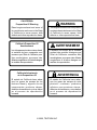
1
OUTFRONT FLAIL
MOWER
SETUP, PARTS & MAINTENANCE MANUAL
E
OUTFRONT FLAIL MOWER
F
MODELS:
956021 - FLAIL 60 IN, 700 FL HYD
956025 - FLAIL 60 IN, 700 FL/TURFCAT HYD
WARNING: If incorrectly used this machine can cause severe injury. Those who
use and maintain this machine should be trained in its proper use, warned of its
dangers and should read the entire manual before attempting to set up, operate,
adjust or service the machine.
2722327 REV00
CALIFORNIA
Proposition 65 Warning
Diesel engine exhaust and some of
its constituents are known to the State
of California to cause cancer, birth
defects and other reproductive harm.
Californie Proposition 65
Avertissement
Les échappements des moteurs diesel
et certains de leurs composés sont
reconnus par l’Etat de Californie pour
être cancérigènes, provoquer des
défauts congénitaux et d’autres dangers
en matière de reproduction.
WARNING
The engine exhaust from this product
contains chemicals known to the State
of California to cause cancer, birth
defects or other reproductive harm.
AVERTISSEMENT
L’émission du moteur de ce matériel
contient des produits chimiques que
l’Etat de Californie considère être
cancérigènes, provoquer des défauts
congénitaux et d’autres dangers en
matière de reproduction.
California Advertencia
de la Proposicion 65
El estado de California hace saber
que los gases de escape de los
motores diesel y algunos de sus
componentes producen cáncer,
defectos de nacimiento y otros daños
en el proceso de reproducción
humana.
ADVERTENCIA
El estado de California hace saber
que los gases de escape de este
producto contienen productos
quÍmicos que producen cáncer,
defectos de nacimiento y otros daños
en el proceso de reproducción
humana.
© 2000, TEXTRON INC
CONTENTS
OUTFRONT
FLAIL
MOWER
IMPORTANT MESSAGE
Thank you for purchasing this Textron product. You have purchased a world class mowing product, one of the best
designed and built anywhere.
This machine comes with an Operation and Safety Manual and a Parts and Service Manual. The useful life and
good service you receive from this machine depends to a large extent on how well you read and understand these
manuals. Treat your machine properly, lubricate and adjust it as instructed, and it will give you many years of reliable
service.
Your safe use of this Textron product is one of our prime design objectives. Many safety features are built in, but
we also rely on your good sense and care to achieve accident-free operation. For best protection, study the manuals
thoroughly. Learn the proper operation of all controls. Observe all safety precautions. Follow all instructions and
warnings completely. Do not remove or defeat any safety features. Make sure those who operate this machine
are as well informed and careful in its use as you are.
See an authorized dealer for any service or parts needed. Textron service ensures that you continue to receive
the best results possible from Textron’s products. You can trust Textron replacement parts because they are
manufactured with the same high precision and quality as the original parts.
Textron designs and builds its equipment to serve many years in a safe and productive manner. For longest life,
use this machine only as directed in the manuals, keep it in good repair and follow safety warnings and instructions.
You'll always be glad you did.
Textron Turf Care And Specialty Products
One Bob Cat Lane
Johnson Creek, WI 53038-0469
TABLE OF CONTENTS
PARTS FIGURES
PAGE
1.0 Safety Information
Safety ........................................................................................................................................................................ 2
Decals ....................................................................................................................................................................... 3
2.0 Important Information
Important Information ............................................................................................................................................... 3
3.0 Assembly & Setup Instructions
Installing Flail Mower ............................................................................................................................................. 4-7
4.0 General Information
General ..................................................................................................................................................................... 8
Removing Cutting Unit From Tractor ........................................................................................................................ 8
Cutting Height ........................................................................................................................................................ 8-9
5.0 Maintenance
Tires ........................................................................................................................................................................ 10
Flail Blade Inspection ............................................................................................................................................. 10
Drive Belt ................................................................................................................................................................ 11
Hydraulic Hoses ...................................................................................................................................................... 11
Lubrication .............................................................................................................................................................. 12
Storage & Specifications ........................................................................................................................................ 12
6.0 Parts Section
Flail Housing .............................................................................. Figure 1 ......................................................... 14-15
Drive Assembly .......................................................................... Figure 2 ......................................................... 16-17
Pusharms & Hydraulics ............................................................. Figure 3 ......................................................... 18-19
Caster Assembly ........................................................................ Figure 4 ......................................................... 20-21
Cross Reference ..................................................................................................................................................... 22
7.0 Textron Warranty
Warranty ............................................................................................................................................................ 23-24
10-2000-TTCSP
1
1 SAFETY
NOTICE !!!
Unauthorized modifications may present extreme
safety hazards to operators and bystanders and
could also result in product damage.
OUTFRONT
FLAIL
MOWER
This symbol means:
ATTENTION!
BECOME ALERT!
Your safety and the safety of others is involved.
Textron Turf Care And Specialty Products strongly
warns against, rejects and disclaims any modifications, add-on accessories or product alterations that
are not designed, developed, tested and approved
by Textron Turf Care And Specialty Products Engineering Department. Any Textron Turf Care And
Specialty Products product that is altered, modified
or changed in any manner not specifically authorized
after original manufacture–including the addition of
“after-market” accessories or component parts not
specifically approved by Textron Turf Care And
Specialty Products–will result in the Textron Turf
Care And Specialty Products Warranty being voided.
Any and all liability for personal injury and/or property
damage caused by any unauthorized modifications,
add-on accessories or products not approved by
Textron Turf Care And Specialty Products will be
considered the responsibility of the individual(s) or
company designing and/or making such changes.
Textron Turf Care And Specialty Products will vigorously pursue full indemnification and costs from any
party responsible for such unauthorized post-manufacture modifications and/or accessories should personal injury and/or property damage result.
Signal word definitions:
The signal words below are used to identify levels of
hazard seriousness. These words appear in this
manual and on the safety labels attached to Textron
Turf Care And Specialty Products machines. For
your safety and the safety of others, read and follow
the information given with these signal words and/or
the symbol shown above.
DANGER indicates an imminently hazardous
situation which, if not avoided, WILL result in death
or serious injury.
WARNING indicates a potentially hazardous situation
which, if not avoided, COULD result in death or
serious injury.
CAUTION indicates a potentially hazardous situation
which, if not avoided, MAY result in minor or moderate
injury. It may also be used to alert against unsafe
practices or property damage.
CAUTION used without the safety alert symbol
indicates a potentially hazardous situation which, if
not avoided, MAY result in property damage
MODEL NUMBER: This number appears on
sales literature, technical manuals and price lists.
SERIAL TAG
2
SERIAL NUMBER: This number appears only
on your mower. It contains the model number
followed consecutively by the serial number. Use
this number when ordering parts or seeking
warranty information.
IMPORTANT INFORMATION 2
OUTFRONT
FLAIL
MOWER
1.1 DECALS___________________________________________________
4 3 2 1 0
5
75075A
0.0
0.5
1.0
1.5
2.0
2.5
3.0
3.5
4.0
0.0
0.5
1.0
1.5
2.0
2.5
6
F
E
D
C
B
A
2721589
7 8
0
1
2
3
4
5
6
7
8
-
A
A
A
A
A
D
D
F
F
A
B
C
D
E
F
0
1
2
3
4
5
6
7
8
0
1
2
3
4
5
2.0 IMPORTANT INFORMATION __________________________________
The set-up and testing of the unit should always be
performed by a trained technician, familiar with the
operation of this equipment.
Read each instruction completely and make sure you
understand it before proceeding with the assembly.
Stay alert for potential hazards and obey all safety
precautions.
The RIGHT and LEFT, FRONT and REAR of the
cutting unit are referenced from the operator’s seat on
the tractor.
Flail Mowers
Flail mowers are shipped complete with cutting blades
assembled. Hydraulic hoses, casters and pusharms
are shipped loose. Follow instructions in Section 3.0
when installing cutting unit to tractor. Refer to Section
4.2 to adjust cutting height.
Hydraulic Motors
Before disconnecting any hydraulic lines thoroughly
clean fittings and other components. Be prepared to cap
or plug open hoses and ports to prevent contamination
to the hydraulic system.
Do not attempt to drive the tractor
unless you are familiar with this type of equipment
and know how to operate all controls correctly.
3
3 ASSEMBLY & SETUP
OUTFRONT
FLAIL
MOWER
3.0 INSTALLING FLAIL MOWER __________________________________
Before installing or disconnecting any hydraulic lines thoroughly clean fittings and other components. Be
prepared to cap or plug open hoses and ports to prevent contamination from entering the hydraulic system.
1. Attach hoses supplied with cutting unit to tractor
implement valve as shown.
• Connect longer hose to the pressure side of the
implement valve.
• Connect shorter hose to the return side of the
implement valve.
PRESSURE
RETURN
2. Install the lift support plate (A) using (4) 3/8"-18 X 1" bolts (B) and (4) 3/8"-18 nuts (C) as shown.
C
A
B
B
C
4
ASSEMBLY & SETUP 3
OUTFRONT
FLAIL
MOWER
3. Install right hand pusharm (D) and left hand pusharm (E) on tractor in positions shown using (2) 5/8"-18 X
3" bolts (F), (2) 5/8" lockwashers (G) and (2) 5/8"-18 nuts (H).
NOTE: Left hand pusharm (E) has larger offset.
4. Roll cutting unit towards tractor lining up pusharm brackets with pusharms on tractor. Attach using cotter
pins to (2) pivot pins (I) then insert pins and secure with (2) quick pins (J) with the quick pins on the
outside as shown.
NOTE: If necessary, raise the front of the cutting unit onto a block to allow pin holes to line up. It may be
necessary to tap one pivot pin (F) into hole when installing arms.
J
D
G
H
I
J
E
F
PUSHARM
MOUNT ON
TRACTOR
5
3 ASSEMBLY & SETUP
OUTFRONT
FLAIL
MOWER
5. Connect hoses from tractor to the motor as
shown. Refer to Step one photo to ensure the
pressure hose gets connected to the pressure
side of the motor and that the return hose gets
connected to the return side of the motor.
PRESSURE
6. Connect drain line hose shipped loose with the
cutting unit to the drain fitting on the motor and
connect other end of drain hose to the drain line
on the tractor.
DRAIN
RETURN
7. Route larger 5/8" pressure and return hoses through clamp (N) and secure clamps to cutting unit using (1)
5/16"-18 X 2-1/2" bolt (K), (1) 5/16" lockwasher (L) and (1) 5/16"-18 nut (H) as shown. Route the smaller
3/8" drain line hose next to the return line and secure return hose and drain line using hose clamp and
rubber liner (M) as shown. Rotate the clamp tightening mechanism to the bottom of the two hoses before
securing. Maintain the drain line hose as low as possible.
NOTE: Drain line connection on the tractor must be loosened to allow hose to be rotated for best hose
routing. Retighten hose fitting on the tractor after connecting drain line hose from cutting unit.
K
L
N
O
DRAIN LINE
FROM
TRACTOR
M
6
ASSEMBLY & SETUP 3
OUTFRONT
FLAIL
MOWER
8. Start tractor and lower deck lift to expose deck lift chains. Attach deck lift chains to cutting unit using
(2) 5/16"-18 X 1-1/4" bolts (P), (2) 5/16" washers (Q) and (2) 5/16"-18 nuts (R) as shown.
9. Connect both cutting unit springs (U) to spring mount bracket on tractor using (2) 3/8"-16 X 1-1/2" bolts (T)
and (4) 3/8"-16 locking flange nuts (S) as shown.
10. Start tractor and raise the cutting unit into the transport position. Connect the bottom of the cutting unit
springs (U) using (2) 3/8"-16 X 1" bolts (V), (2) 3/8" washers (W), (2) spacers (X) and (2) 3/8"-16 locking
flange nuts (S) as shown. Check for clearance of drain hose to tractor brake latch. Reposition hose or
clamp if necessary.
11. Install casters using spacers and quick pins.
LIFT CHAINS
ON TRACTOR
SPRING MOUNT
ON TRACTOR
R
S
P
Q
S
T
S
U
X
V
W
12. Lower cutting unit by lowering the deck lift.
Attach deck stops (Y) using (4) 5/16"-18 X 1" bolt
(Z) and (4) 5/16"-18 nuts as shown.
13. Attach rubber bumpers (BB) using (2) 5/16"-18
locking flange nuts (CC) as shown.
14. After installation run mower and check for proper
rotation. Correct rotation is counterclockwise
when viewed from the “drive side”. If rotation is
wrong reverse hydraulic lines at deck motor.
Z
AA
CC
BB
Y
CC
Z
Y
AA
15. Set cutting height, see Section 4.2
BB
7
4 GENERAL INFORMATION
OUTFRONT
FLAIL
MOWER
4.0 GENERAL _________________________________________________
To prevent serious injury, always
disengage all drives, lower implement to the ground,
engage parking brake, stop engine and remove the
ignition key before you adjust, clean or repair this
equipment.
1. Adjustments and maintenance should always be
performed by a qualified technician. If proper
adjustment cannot be made, contact an authorized Distributor.
2. Do not wear jewelry or loose fitting clothing when
adjusting or repairing any equipment.
Be careful to prevent entrapment
of the hands and fingers between moving and fixed
components of the machine.
3. Inspect the equipment on a regular basis. Establish a maintenance schedule and keep detailed
records.
• Keep the mower clean and moving parts
properly adjusted and lubricated.
• Replace worn or damaged parts before
operating the machine.
• Keep shields in place and all hardware
securely fastened.
• Keep tires properly inflated.
4. Wash the unit after each use. Do not wash any
portion of the equipment while it is hot. Do not
spray water directly at bearing housings and
seals. Do not use high pressure spray or steam.
5. Repair damaged metal surfaces.
Use the illustrations in the Parts Catalog as reference
for the disassembly and reassembly of components.
4.1 REMOVING CUTTING UNIT FROM TRACTOR ____________________
1. Lower implement to the ground, engage parking
brake, disengage all drives, stop engine and
remove the ignition key
NEVER open or loosen
hydraulic lines under pressure.
Hydraulic fluid escaping under pressure can
have sufficient force to penetrate skin. If fluid
is injected into the skin it must be surgically
removed within a few hours by a doctor
familiar with this form of injury or gangrene
may result.
2. Allow sufficient time for hydraulic components to
cool.
3. Disconnect push arms, springs and chain from
cutting unit.
4. Disconnect hydraulic hoses from fittings on motor
and remove case drain extension and hose
clamps. Disconnect tractor hoses on attachment.
Plug or cap all open hydraulic connections to
prevent contamination.
5. Store push arms with attachment.
4.2 CUTTING HEIGHT___________________________________________
Cutting height for vertical mowers can be adjusted
between 0-4 in. (0-102 mm).
Actual cutting height may vary somewhat from the
heights given depending on turf conditions and other
factors.
8
NOTE: When cutting undulating areas, lower
cutting heights may cause scalping. Adjust
height accordingly to prevent turf damage.
OUTFRONT
FLAIL
MOWER
Tire pressure
Maintain air pressure in caster wheels at 22-24 psi
(152-165 kPa) to improve accuracy of cutting height.
Check air pressure in caster tires, while tires are cool.
Keep inflation pressures on both tires the same to
ensure a level cut.
Preparation
Park the tractor on a flat, level surface. Raise the
cutting unit until the caster wheels are 3-4 in. (75100mm) off the ground. Stop engine and remove key
from ignition. Place blocks under cutting unit so it is
supported on all sides.
It is not necessary to remove cutting unit from tractor
when making height adjustments.
To prevent serious injury,
lower deck until it is resting completely on the
supports. This will prevent it from accidentally
lowering while making adjustments. Disengage all drives, engage parking brake, stop
engine and remove ignition key.
Flail Mower Adjustment
GENERAL INFORMATION 4
Metric equivalents are given for reference and
are not listed on decal attached to mower.
Column 1 - Height of cut
Column 2 - Push arm adjustment
Column 3 - Rear roller adjustment
Column 4 - Arrangement of spacers
When cutting at 1 in., (25 mm) and below, assemble the lift chain to the upper hole in
bracket on cutting unit.
Example: 2 in. (50 mm) height of cut - rear roller
slightly raised
1 Locate height of cut on chart.
2 Position push arm adjustment pin in hole 4.
3 Adjust rear roller in hole (A).
4 Place four spacers on bottom of spindle as
shown. Store remaining spacers and washers
on top.
Example: 1 in. (15 mm) height of cut - rear roller
on ground
1
2
3
4
Locate height of cut on chart.
Position push arm adjustment pin in hole 4.
Adjust rear roller in hole (A).
Place four spacers on bottom of spindle as
shown. Store remaining spacers and washers
on top.
Vertical mowers can be adjusted two different ways
depending on turf conditions and type of cut desired.
For normal operation, adjust both the push arm and
rear roller, along with the caster wheels - top portion
of chart. This allows the height of cut to be adjusted
between 0-4 in. (0-100 mm) and lifts the rear roller
slightly off ground during operation. This reduces
wear to the rear roller and provides anti-scalping
control.
To improve anti-scalping control or create striping
effects, remove adjusting pin from push arm and
adjust height using only rear roller and caster wheel bottom portion of chart. This adjustment allows the
rear roller to ride over the ground surface and limits
height of cut from 0 to 2-1/2 in.(0-63 mm).
NOTE: With the rear roller adjusted down,
roller bearing life is reduced.
1. The chart shows the height adjustment decal
used on the flail. Determine the type of adjustment desired, select cutting height and follow
across chart to make appropriate adjustments.
1
2
43210
in. (mm)
0.0 ( 0)
0.5 (13)
1.0 (25)
1.5 (38)
2.0 (51)
2.5 (64)
3.0 (76)
3.5 (87)
4.0 (102)
0.0 ( 0)
0.5 (13)
1.0 (25)
1.5 (38)
2.0 (51)
2.5 (64)
3
4
DEF
C
B
A
8765
0
1
2
3
4
5
6
7
8
A
A
A
A
A
D
D
F
F
A
B
C
D
E
F
0
1
2
3
4
5
6
7
8
0
1
2
3
4
5
9
5 MAINTENANCE
OUTFRONT
FLAIL
MOWER
5.0 TIRES _____________________________________________________
1. It is important to keep the same inflation pressure
on both tires to maintain the mower level and
prevent uneven cutting.
2. Check the pressure once a month while the tires
are cool. Use an accurate, low pressure tire
gauge.
Caster
22 to 24 psi (152 to 165 kPa)
3. Keep tires properly inflated to prolong tire life
Unless you have the
proper training, tools, and experience, Do Not
attempt to mount a tire on a rim. Improper
mounting can produce an explosion, which
may result in serious injury.
5.1 FLAIL BLADE INSPECTION ___________________________________
Every 50 hours or whenever mower is removed from
tractor, carefully examine the shackles (C) and
blades (D) to be sure they are in good operating
condition.
Operating the mower with missing
or damaged parts can cause severe vibration and
damage to other components.
1. Remove any debris that is wound around the
rotor.
2. If only one edge of a double edged blade is worn,
remove blades (D), turn them 180° and reassemble to rotor with the good cutting edge facing
forward.
3. If all the blades are worn on one side only, the
entire rotor can be removed and turned 180°.
• Remove belt cover, drive belt and rotor
pulley.
• Remove bumper guard, remove skid shoes
and rotor bearing mounting bolts from both
sides of housing.
• Slide rotor out of housing (bearings do not
have to be removed) turn rotor 180° and slide
rotor back into housing.
4. Carefully reassemble rotor and all components.
Rotor must be centered within the housing.
Grease fittings on both rotor bearings face top of
housing.
C
D
10
MAINTENANCE 5
OUTFRONT
FLAIL
MOWER
5.2 DRIVE BELT _______________________________________________
Keep belt and pulleys clean. Belt is self adjusting.
Inspect belt periodically and replace if it appears worn
or frayed.
1. To replace belt, remove belt cover, then loosen
hex nuts (A) to relieve belt tension. Install new
belt as shown.
A
B
2. Adjust spring to dimensions shown below to set
correct belt tension.
B
4 ± 1/16 in. (102 ± 1.6 mm)
3. Install belt cover after adjustment.
5.3 HYDRAULIC HOSES ________________________________________
To prevent serious injury
from hot, high pressure oil, never use your
hands to check for oil leaks, use paper or
cardboard.
Hydraulic fluid escaping under pressure can
have sufficient force to penetrate skin. If fluid
is injected into the skin it must be surgically
removed within a few hours by a doctor
familiar with this form of injury or gangrene
may result.
1. Inspect hoses and tubes daily. Look for wet
hoses or oil spots and replace worn or damaged
hoses and tubes before operating the machine.
2. Keep the hose from twisting. Twisted hoses can
cause couplers to loosen as the hose flexes
during operation resulting in oil leaks.
3. Refer to the tractor’s manual for additional
information.
11
5 MAINTENANCE
OUTFRONT
FLAIL
MOWER
5.4 LUBRICATION ______________________________________________
Lubricate grease fittings every 50 hours of operation
or more frequently when operating in extremely dusty
conditions.
Flail Mowers
(1) Caster Spindles
(2) Rotor Bearings
(3) Roller Bearings
(4) Push Arm Pivots
(5) Motor Spine Adaptor
1. Always clean grease fittings before and after
lubricating.
2. Lubricate with grease that meets or exceeds
NLGI Grade 2 specifications.
4. Remove motor and lubricate motor adapter spline
(5) using NLGI Grade 2, every 100 hours of
operation.
3. Apply grease with a manual grease gun and fill
slowly until grease begins to seep out or pressure
is felt. Never use compressed air guns.
5. For smooth operation of other pivot and friction
points, apply several drops of SAE 30 wt. oil
every 50 hours or as required.
1
2
2
3
Both
Sides
5
4
4
5.5 STORAGE & SPECIFICATIONS ________________________________
Lubricate all the fittings, then wash the mower.
Repair and paint damaged or exposed metal with touch-up paint.
Tighten all hardware, replace worn or damaged components. Loosen belt tension.
Resharpen and balance the cutter blades. Apply a light coat of rust preventive oil on sharpened edges.
Clean the tires thoroughly and store the mower so that the load is off the tires. If the mower is not on jack-stands,
check the tire pressure at regular intervals and reinflate as necessary.
Keep the machine and all its accessories clean, dry and protected from the elements during storage.
FLAIL MOWER
12
MODEL NUMBER
956021, 956025
WIDTH OF CUT
60 " (153 mm)
SHIPPING WEIGHT
366 lbs (166 kg)
ADJUSTABLE CUTTING HEIGHT
0-4 " (0-102 mm)
TIRE PRESSURE
22-24 psi (152-165 kPa)
DRIVE
GEAR TYPE HYDRAULIC MOTOR
OUTFRONT
FLAIL
MOWER
PARTS SECTION 6
PARTS
SECTION
13
FLAIL HOUSING
OUTFRONT
FLAIL
MOWER
FIGURE 1
9
33
35
13
23
23
15
24
8
25
11
1
A
19
6
19
26
34
7
4
21
22
5
27
30 29
28
30 31
32
20
12
32
17
3
16
2
19
8
11
18
10
25
19
25
14
20
A
19
14
18
19
25
OUTFRONT
FLAIL
MOWER
ITEM
1
2
3
4
5
6
7
8
9
10
11
12
13
14
15
16
17
18
19
20
21
22
23
24
25
26
PART NO.
2720427
162887.7
362320
64141-6
1001340
1000414.7
64229-03
3007486
3002685
362229
35027N
471219
162881
131407.7
162888.7
162932
438009
64229-04
400260
400336
131406.7
64163-31
64123-54
85010N
64141-4
48053-07
QTY.
1
1
1
6
1
1
2
2
1
2
2
2
1
2
1
1
2
12
12
12
1
2
15
2
12
4
27
28
29
30
31
32
5001085
3002833
400234
362226
64163-43
64151-24
365769
144
72
72
144
72
144
33
34
35
64229-02
64123-16
64163-29
9
2
9
FLAIL HOUSING
2721217-01
DESCRIPTION
S-FLAIL HOUSING W/DECALS
ROLLER PLATE ASSEMBLY LH
KEY-PARALLEL
NUT-WLF 5/16-18
ROTOR ASSEMBLY
BUMPER GUARD ASSEMBLY
NUT-NYLOCK 3/8-16
BEARING HOUSING
REAR FLAP
BEARING -ROTOR
ZERK FITTING
FITTING-GREASE 1/8 PTF
ROLLER ASSEMBLY
SKID ASSEMBLY
ROLLER PLATE ASSEMBLY RH
PULLEY
SET SCREW
NUT-NYLOCK 7/16-14
SCREW-3/8-16 X 7/8 HEX HEAD
SCREW-7/16-14 X 1-1/4 HEX HEAD
SHIELD ASSEMBLY
WASHER-25/64 X 1 X 12 GA
BOLT-HEX 5/16-18 X 3/4
ZERK 1/4-28 SELF THREAD
NUT-WLF 3/8-16
BUSHING
BLADE KIT
BLADE
SCREW-5/16-24 X 2 HEX HEAD
SHACKLE
FLAT WASHER-5/16
NUT-CENTERLOCK 5/16-24
SPACER
FIGURE 1
SERIAL NUMBER/NOTES
INCLUDES ROTOR & ITEMS 27-32
INCLUDES ITEMS 27-32
NUT-NYLOCK 5/16-18
BOLT-HEX 3/8-16 X 1-1/4
21/64 X 1 X 11GA
15
DRIVE ASSEMBLY
OUTFRONT
FLAIL
MOWER
FIGURE 2
23
19
23
17
20
23
5
27
28
6
17
25
21
3
24
15
14
2
22
26
7
17
23
9
26
16 13
10
12
1
2
16
11
8
17
9
4
20
18
17
OUTFRONT
FLAIL
MOWER
ITEM
1
2
3
4
5
6
7
8
9
10
11
12
13
14
15
16
17
18
19
20
21
22
23
24
25
26
27
28
PART NO.
2198229
64139-08
390469.7
64123-117
64123-50
64123-87
2721213.7
162882.7
2228047
362244
64163-19
64123-31
2238008
362245
400616
64151-6
64025-19
64006-05
362246
400260
64044-2
64163-31
64229-03
362228
338548
2720915.7
64164-27
2218152-03
2218152-05
00459
00460
QTY.
1
4
1
1
1
2
1
1
2
1
1
1
1
1
1
1
5
1
1
3
2
2
6
1
1
2
1
1
1
1
1
DRIVE ASSEMBLY
2721217-02
DESCRIPTION
PULLEY-6.50 NOM DIA
BOLT-WLF 5/16-18 X 3/4
COVER-BELT
BOLT-HEX 1/2-13 X 1-1/2
BOLT-HEX 3/8-16 X 1
BOLT-HEX 3/8-16 X 1-3/4
WELDMENT-MOTOR MOUNT
IDLER ARM ASSEMBLY
BUSHING-NYLINER
SPACER-IDLER
WASHER-33/64 X 1-1/4 X 12GA
BOLT-HEX 1/2-13 X 3
IDLER PULLEY
SPACER-IDLER PULLEY
NUT-HEX LOCK 5/8-11
NUT-NYLOCK 5/8-11
NUT-HEX 1/2-13
LOCKWASHER-HELICAL 1/2
STUD-SPRING ADJUSTABLE
BOLT-HEX 3/8-16 X 7/8
SCREW-SET 5/16-18 X 3/8
WASHER
NUT-HEX 3/8-16
SPRING-EXTENSION
BELT-DRIVE
PLATE-MOTOR SUPPORT
KEY-1/4 X 1/4 X 1
MOTOR-16CC
MOTOR-20CC
LABEL-PRESSURE
LABEL-RETURN
FIGURE 2
SERIAL NUMBER/NOTES
USE ON 956021
USE ON 956025
LOCATED ON MOTOR
LOCATED ON MOTOR
17
PUSHARMS & HYDRAULICS
OUTFRONT
FLAIL
MOWER
FIGURE 3
42
LIFT CHAIN
ON TRACTOR
41
40
43
40
42
39
43
36
37
38
41
30
39
33
SPRING MOUNT
ON TRACTOR
26
28
26
2
28
29
13
16
15
28
26
31
3
27
26
16
PUSHARM
MOUNT ON
TRACTOR
14
18
34, 35
25
32
5
23, 24
SERIAL
PLATE
9
21
20
7
1
15
17
12, 44
8
18
11
6
30
22
10
19
4
DECK DRAIN
HOSE ON
TRACTOR
OUTFRONT
FLAIL
MOWER
ITEM
1
2
3
4
5
6
7
8
9
10
11
12
13
14
15
16
17
18
19
20
21
22
23
24
25
26
27
28
29
30
31
32
33
34
35
36
37
38
39
40
41
42
43
44
PART NO.
2692286-02
2192390
64151-2
64123-133
2208139
64123-12
64229-02
158006-10
2692238-05
64006-04
64025-16
65362-01
2198162
2000677
2721589
75075A
158007-05
2692238-06
2721218
2721219
3000439
64173-02
363215
460316
460050
64123-50
23009A
64141-4
64123-70
64229-03
64163-53
64251-003
2720791.7
108102
343539
64123-47
64163-46
64151-1
523126
64141-6
64229-02
64123-68
2721174.7
108094-01
QTY.
1
1
2
2
1
1
1
1
1
2
2
1
2
1
2
2
2
1
1
1
2
2
2
2
2
8
2
6
2
4
2
1
1
2
4
2
2
2
2
2
4
4
2
1
PUSHARMS & HYDRAULICS
2721217-03
DESCRIPTION
HOSE-3/8 ORS/ORS MALE X 19.00
DECK-HOOK
3/8-16 HH LOCK NUT
BOLT-HEX 5/8-18 X 3
CLAMP-TUBE
BOLT-HEX 5/16-18X2-1/2
NUT-NYLOCK 5/16-18
FITTING-ORB/ORS
HOSE-5/8 ORS/ORS X 45.87
LOCKWASHER 5/8
NUT-HEX 5/8-18
RUBBER-CLAMP 4IN
SPRING-EXTENSION
DECAL-DANGER
DECAL-FLAIL HEIGHT OF CUT
DECAL-CPSC WARNING
FITTING-90 ORS/ORB
HOSE-5/8 ORS/ORS X 48.75
ASSEMBLY-PUSHARM RH
ASSEMBLY-PUSHARM LH
PIN-CLEVIS 1/2" X 3-3/4"
PIN-SNAP RING
SHAFT-CLEVIS
HAIRPIN-COTTER
COTTER PIN 3/16" X 1-1/4"
BOLT-HEX 3/8-16 X 1"
SPACER
NUT-WLF 3/8-16
BOLT-HEX 3/8-16 X 1-1/2
NUT-NYLOCK 3/8-16
WASHER-0.391 X 1.50 X 9 GA
WASHER-M8
PLATE-LIFT SUPPORT
ZERK
BUSHING
BOLT-HEX 5/16-18 X 1-1/4
WASHER-0.383/0.393X0.88 X 7GA
NUT-CENTERLOCK 5/16-18
BUMPER-RUBBER
NUT-WLF 5/16-18
NUT-NYLOCK 5/16-18
BOLT-HEX 5/16-18 X 1
BRKT-UPSTOP, FLAIL
CLAMP-HOSE SAE20
FIGURE 3
SERIAL NUMBER/NOTES
INCLUDES ITEMS 34 & 35
INCLUDES ITEMS 34 & 35
19
CASTER ASSEMBLY
OUTFRONT
FLAIL
MOWER
FIGURE 4
12
11
10
2
1
9
4
8
7
5
5
6
20
3
OUTFRONT
FLAIL
MOWER
ITEM
1
2
3
4
5
6
7
8
9
10
11
12
PART NO.
131596.7
64173-04
1003769
3003207
64163-57
460056
403578
444310
446118
PJH1054
64163-07
64163-25
QTY.
2
2
2
2
4
2
2
2
2
16
2
2
CASTER ASSEMBLY
2721217-04
DESCRIPTION
CASTER WHEEL SPINDLE ASSEMBLY
PIN-KLIK TYPE
WHEEL AND TIRE ASSEMBLY
SHAFT-CASTER WHEEL
WASHER-2.00 X 0.766 X 9 GA
COTTER PIN 3/16" X 2"
SCREW-#10-24 X 1" HEX HEAD
NUT-#10-24 HEX
LOCKWASHER-#10
SPACER
SPACER
WASHER 1-1/32 X 2 X 11GA
FIGURE 4
SERIAL NUMBER/NOTES
21
CROSS REFERENCE
PART NO.
00459
00460
1000414.7
1001340
1003769
108094-01
108102
131406.7
131407.7
131596.7
158006-10
158007-05
162881
162887.7
162888.7
162932
2000677
2192390
2198162
2208139
2218152-03
2218152-05
23009A
2692238-05
2692238-06
2692286-02
2720427
2720791.7
2721174.7
2721218
2721219
2721589
3000439
3002685
3002833
3003207
3007486
343539
35027N
362226
362229
362320
363215
365769
400234
400260
400336
403578
438009
444310
446118
460050
22
DESCRIPTION
OUTFRONT
FLAIL
MOWER
FIG/ITEM
LABEL-PRESSURE
LABEL-RETURN
BUMPER GUARD ASSEMBLY
ROTOR ASSY
WHEEL/TIRE 11X4X5
CLAMP-HOSE SAE20
LUB,FITTING,65 DEG
SHIELD ASY
SKID ASY
SPINDLE
FITTING-ORB/ORS
FITTING-90 ORS/ORB
ROLLER ASY
ROLLER PLT
RLR PLT AS
PULLEY
LABEL-DANGER/WARNING
DECK HOOK
SPRING-EXTENSION
CLAMP-TUBE
MOTOR-16CC
MOTOR-20CC
SPACER,ENGINE MOUNT
HOSE-5/8 ORS/ORS X 45.87
HOSE-5/8 ORS/ORS X 48.75
HSE-3/8 ORS/ORS MALEX19.0
S FLAIL HOUSING W/DECALS
PLATE-LIFT SUPPORT
BRKT-UPSTOP, FLAIL
S WLDMT-PUSHARM RH
S WLDMT-PUSHARM LH
LABEL-FLAIL HEIGHT OF CUT
PIN, CLEVIS
FLAP, REAR
BLADE,FLAIL
SHAFT, CASTER WHEEL
HOUSING, BEARING
BUSHING
ZERK FITTING
SHACKLE
BEARING
KEY, PARALLEL
REAR SHAFT
SPACER-FLAIL
BLT-HEX 5/16-24X2
SCREW 3/8-16 X 7/8 HEX
SCREW 7/16-14 X 1-1/4 HEX
SCREW 10-24 X 1 HEX
SCREW-SET
NUT-HEX #10-24
LOCKWASHER-#10
COTTER PIN
2 /28
2 /28
1 /6
1 /5
4 /3
3 /44
3 /34
1 /21
1 /14
4 /1
3 /8
3 /17
1 /13
1 /2
1 /15
1 /16
3 /14
3 /2
3 /13
3 /5
2 /28
2 /28
3 /27
3 /9
3 /18
3 /1
1 /1
3 /33
3 /43
3 /19
3 /20
3 /15
3 /21
1 /9
1 /27
4 /4
1 /8
3 /35
1 /11
1 /29
1 /10
1 /3
3 /23
1 /32
1 /28
1 /19
1 /20
4 /7
1 /17
4 /8
4 /9
3 /25
PART NO.
460056
460316
471219
48053-07
523126
64006-04
64025-16
64123-12
64123-133
64123-16
64123-47
64123-50
64123-50
64123-54
64123-68
64123-70
64141-4
64141-4
64141-6
64141-6
64151-1
64151-2
64151-24
64163-07
64163-25
64163-29
64163-31
64163-43
64163-46
64163-53
64163-57
64173-02
64173-04
64229-02
64229-02
64229-02
64229-03
64229-03
64229-04
64251-003
65362-01
75075A
85010N
PJH1054
DESCRIPTION
FIG/ITEM
COTTER PIN 3/16 X 2
PIN COTTER, INTERNAL HAIR
FITTING-STR.-STEW.WARNER
BEARING-FLANGED BRONZE
BUMPER-RUBBER
LOCKWSHR-HELICAL 5/8
NUT-HEX 5/8-18
BLT-HEX 5/16-18X2-1/2
BLT-HEX 5/8-18X3
BLT-HEX 3/8-16X1-1/4
BLT-HEX 5/16-18X1-1/4
BLT-HEX 3/8-16X1
BLT-HEX 3/8-16X1
BLT-HEX 5/16-18X3/4
BLT-HEX 5/16-18X1
BLT-HEX 3/8-16X1-1/2
NUT-WLF 3/8-16
NUT-WLF 3/8-16
NUT-WLF 5/16-18
NUT-WLF 5/16-18
5/16-18 HEX LOCK NUT
3/8-16 HH LOCK NUT
HEX CL NUT 5/16-24
1-1/32X1-3/4X1/4 WASH
1-1/32X2X11GA WASHER
21/64X1X11GA.WASHER
WASH.25/64X1X12 GA
WSHR.443/.454X1X11GA
WSHR.383/.393X.88X7GA
WASHER .391X1.50X9GA
WSHR 2.00X.766X9GA
PIN, SNAP RING
QUICK PIN
LOCK NUT-NYLON 5/16-18
LOCK NUT-NYLON 5/16-18
LOCK NUT-NYLON 5/16-18
LOCK NUT-NYLON 3/8-16
LOCK NUT-NYLON 3/8-16
S LCK NUT-NYLN 7/16-14
WHSR-M8
RUBBER-CLAMP 4IN
LABEL, CPSC DANGER
ZERK, 1/4-28 STR SELF THRD
SPACER, CASTER (BUNTON)
4 /6
3 /24
1 /12
1 /26
3 /39
3 /10
3 /11
3 /6
3 /4
1 /34
3 /36
2 /5
3 /26
1 /23
3 /42
3 /29
1 /25
3 /28
1 /4
3 /40
3 /38
3 /3
1 /31
4 /11
4 /12
1 /35
1 /22
1 /30
3 /37
3 /31
4 /5
3 /22
4 /2
1 /33
3 /41
3 /7
1 /7
3 /30
1 /18
3 /32
3 /12
3 /16
1 /24
4 /10
OUTFRONT
FLAIL
MOWER
TEXTRON WARRANTY
Textron Turf Care And Specialty Products warrants for one year each new product and accessory, according to the following
terms.
This warranty extends to the original retail purchaser only and commences on the date of original retail purchase. Accordingly
this warranty is not transferable to any subsequent purchasers.
Any part of the product or accessory manufactured by Textron Turf Care And Specialty Products and found in the reasonable
judgement of Textron Turf Care And Specialty Products to be defective in material or workmanship will be repaired or
replaced by an authorized dealer without charge for parts and labor.
The product or accessory including any defective part must be returned to an authorized dealer within the warranty period.
The expense of returning the product or accessory to an authorized dealer for warranty service and the expense of returning
it back to the owner after repair or replacement will be paid for by the owner. Textron Turf Care And Specialty Products'
responsibility in respect to claims is limited to making the required repairs or replacements, and no claim of breach of
warranty shall be cause for cancellation or rescission of the contract of sale of any product or accessory.
Proof of purchase will be required by the authorized dealer to substantiate any warranty claim. All warranty work must be
performed by an authorized dealer.
Textron Turf Care And Specialty Products makes no warranty with respect to engines, tires, batteries, regulators, startergenerators, or other parts not of its manufacture as such parts are usually warranted separately by their respective
manufacturers.
This warranty does not include service items or parts subject to normal wear.
This warranty does not cover any product or accessory that has been subject to misuse, neglect, negligence, or accident, or
that has been operated or maintained in any way contrary to the operating or maintenance instructions as specified in the
Operator’s Manual. The warranty does not apply to any product or accessory that has been altered or modified so as to
adversely affect the product’s operation, performance or durability or that has been altered or modified so as to change its
intended use. In addition, the warranty does not extend to repairs made necessary by normal wear, or by the use of
parts or accessories which in the reasonable judgement of Textron Turf Care And Specialty Products are either incompatible
with the product or adversely affect its operation, performance or durability.
Textron Turf Care And Specialty Products reserves the right to change or improve the design of any product or accessory
without assuming any obligation to modify any product previously manufactured.
THERE ARE NO OTHER WARRANTIES, EXPRESS OR IMPLIED, INCLUDING MERCHANTABILITY AND FITNESS FOR A
PARTICULAR PURPOSE. ALL WARRANTIES OTHER THAN THIS EXPRESS WARRANTY ARE SPECIFICALLY
DISCLAIMED.
TEXTRON TURF CARE AND SPECIALTY PRODUCTS’ OBLIGATION UNDER THIS WARRANTY IS STRICTLY AND
EXCLUSIVELY LIMITED TO THE REPAIR OR REPLACEMENT OF DEFECTIVE PARTS, AND TEXTRON TURF CARE AND
SPECIALTY PRODUCTS DOES NOT ASSUME OR AUTHORIZE ANYONE TO ASSUME FOR IT ANY OTHER OBLIGATION.
TEXTRON TURF CARE AND SPECIALTY PRODUCTS ASSUMES NO RESPONSIBILITY FOR INCIDENTAL,
CONSEQUENTIAL OR OTHER DAMAGES INCLUDING, BUT NOT LIMITED TO, EXPENSE FOR GASOLINE, EXPENSE
OF RETURNING THE PRODUCT TO AN AUTHORIZED DEALER AND EXPENSE OF RETURNING IT BACK TO THE
OWNER. MECHANIC’S TRAVEL TIME, TELEPHONE OR TELEGRAM CHARGES, TRAILERING OR TOWING CHARGES,
RENTAL OF A LIKE PRODUCT WHILE WARRANTY SERVICE IS BEING PERFORMED, TRAVEL, LODGING, LOSS OR
DAMAGE TO PERSONAL PROPERTY, LOSS OF REVENUE, LOSS OF USE OF PRODUCT, LOSS OF TIME OR
INCONVENIENCE.
This warranty gives you specific legal rights. You may also have other rights, which vary from state to state.
Textron Turf Care And Specialty Products * P.O. Box 82409 * Lincoln, Nebraska 68501-2409
23
TEXTRON WARRANTY
OUTFRONT
FLAIL
MOWER
To make a claim under warranty, contact an authorized dealer immediately upon realizing a problem exists. We
recommend having the warranty work performed by the dealer who originally sold you the unit; however, warranty
work can be sought from any authorized dealer. Remember, your unit must be delivered to an authorized dealer
within the warranty period, and all warranty work must be performed only by an authorized dealer. Proof of purchase
will be required by the dealer to substantiate any warranty claim.
EXAMPLES OF ITEMS NOT COVERED UNDER WARRANTY
Provisions of the warranty will not apply to:
–
Normal service requirements arising during the warranty period, such as carburetor or ignition adjustment and
cleaning or wear of a drive belt, brake, clutch linings or starter brushes.
–
Normal service work over and above the repair and replacement of defective parts.
–
Units subject to misuse, neglect, negligence, or accident.
–
Units that have been altered or modified so as to adversely affect their operation, performance or durability or to
change their intended use.
–
Repairs made necessary by the use of parts or accessories which are either incompatible with the unit or adversely
affects the operation, performance or durability.
–
Units not operated or maintained in accordance with the instructions in the Operator’s Manual.
–
Normal cleaning, adjusting or replacing of such items as filter, spark plugs, ignition points, light bulbs, fuses or
starter drive.
–
Periodic checking or adding of lubricants to the unit or service check-up, tune-up or diagnosis.
Expense of delivering the unit to the dealer and expense of returning the unit back to the owner, mechanic’s
travel time, trailering or towing charges, or rental of a like unit during the time warranty repairs are being
performed.
Engines, tires, batteries, regulators and starter-generators manufactured by other than Textron Turf Care
And Specialty Products are not covered under this warranty as such parts are usually warranted by their
respective manufacturers.
This warranty applies only to the original retail purchaser. Second-owner or subsequently owned units are
not covered under warranty.
OWNER’S OBLIGATION AND RESPONSIBILITY
Normal maintenance service and replacement of service items are the responsibility of the owner and as such are
not considered defects in material or workmanship within the terms of the warranty. Individual operating habits and
usage contribute to the need for maintenance service.
See your authorized dealer for proper maintenance and care of your unit. Proper maintenance and care will assist in
keeping your overall operating cost at a minimum.
To validate a warranty claim, it is the owner’s responsibility to maintain all components in proper adjustment and
service the unit as specified in the Operator’s Manual. It is the owner’s responsibility to provide proper lubrication for
all components and provide correct recommended fuel for the unit. It is the owner’s responsibility to maintain the
battery liquid level and charge as specified, as well as maintaining the correct pressure in the unit’s tires.
24