1
OUTFRONT
FLAIL
MOWER
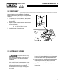
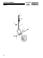
Tire pressure
Maintain air pressure in caster wheels at 22-24 psi
(152-165 kPa) to improve accuracy of cutting height.
Check air pressure in caster tires, while tires are cool.
Keep inflation pressures on both tires the same to
ensure a level cut.
Preparation
Park the tractor on a flat, level surface. Raise the
cutting unit until the caster wheels are 3-4 in. (75100mm) off the ground. Stop engine and remove key
from ignition. Place blocks under cutting unit so it is
supported on all sides.
It is not necessary to remove cutting unit from tractor
when making height adjustments.
To prevent serious injury,
lower deck until it is resting completely on the
supports. This will prevent it from accidentally
lowering while making adjustments. Disengage all drives, engage parking brake, stop
engine and remove ignition key.
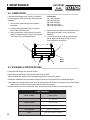
Flail Mower Adjustment
GENERAL INFORMATION 4
Metric equivalents are given for reference and
are not listed on decal attached to mower.
Column 1 - Height of cut
Column 2 - Push arm adjustment
Column 3 - Rear roller adjustment
Column 4 - Arrangement of spacers
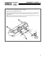
When cutting at 1 in., (25 mm) and below, assemble the lift chain to the upper hole in
bracket on cutting unit.
Example: 2 in. (50 mm) height of cut - rear roller
slightly raised
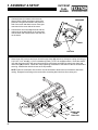
1 Locate height of cut on chart.
2 Position push arm adjustment pin in hole 4.
3 Adjust rear roller in hole (A).
4 Place four spacers on bottom of spindle as
shown. Store remaining spacers and washers
on top.
Example: 1 in. (15 mm) height of cut - rear roller
on ground
1
2
3
4
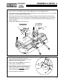
Locate height of cut on chart.
Position push arm adjustment pin in hole 4.
Adjust rear roller in hole (A).
Place four spacers on bottom of spindle as
shown. Store remaining spacers and washers
on top.
Vertical mowers can be adjusted two different ways
depending on turf conditions and type of cut desired.
For normal operation, adjust both the push arm and
rear roller, along with the caster wheels - top portion
of chart. This allows the height of cut to be adjusted
between 0-4 in. (0-100 mm) and lifts the rear roller
slightly off ground during operation. This reduces
wear to the rear roller and provides anti-scalping
control.
To improve anti-scalping control or create striping
effects, remove adjusting pin from push arm and
adjust height using only rear roller and caster wheel bottom portion of chart. This adjustment allows the
rear roller to ride over the ground surface and limits
height of cut from 0 to 2-1/2 in.(0-63 mm).
NOTE: With the rear roller adjusted down,
roller bearing life is reduced.
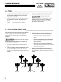
1. The chart shows the height adjustment decal
used on the flail. Determine the type of adjustment desired, select cutting height and follow
across chart to make appropriate adjustments.
1
2
43210
in. (mm)
0.0 ( 0)
0.5 (13)
1.0 (25)
1.5 (38)
2.0 (51)
2.5 (64)
3.0 (76)
3.5 (87)
4.0 (102)
0.0 ( 0)
0.5 (13)
1.0 (25)
1.5 (38)
2.0 (51)
2.5 (64)
3
4
DEF
C
B
A
8765
0
1
2
3
4
5
6
7
8
A
A
A
A
A
D
D
F
F
A
B
C
D
E
F
0
1
2
3
4
5
6
7
8
0
1
2
3
4
5
9