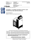
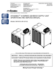
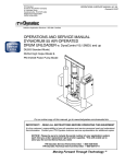
1
ITW Dynatec
An Illinois Tool Works Company
31 Volunteer Drive
Hendersonville, TN 37075 USA
Telephone 615.824.3634
FAX 615.264.5222
OPERATIONS & SERVICE MANUAL #40-35
Revised 9/15/077
Adhesive Application Solutions • ISO 9001 Certified
OPERATIONS AND SERVICE MANUAL
MR1300 HI FLOW SLOT DIE
HOT MELT ADHESIVE APPLICATOR HEADS*
*Manufactured under U.S. Patent # 6,076,711
For an online copy of this manual, go to www.itwdynatec.com/manuals.htm
IMPORTANT ! - READ ALL INSTRUCTIONS BEFORE OPERATING THIS EQUIPMENT
It is the customer’s responsibility to have all operators and service personnel read and understand
this information. Contact your ITW Dynatec customer service representative for additional copies.
NOTICE! Please be sure to include the serial number of your application system
each time you order replacement parts and/or supplies. This will enable us to
send you the correct items that you need.
ITW Dynatec Service Parts Direct Dial: 1-800-538-9540
ITW Dynatec Technical Service Direct Dial: 1-800-654-6711
Moving Forward Through Technology™
ITW Dynatec c. 1999
MR1300 HI FLOW SLOT DIE APPLICATOR Manual #40-35
Revised 7/99
SAFETY INSTRUCTIONS
GENERAL CONSIDERATIONS
SERVICING EQUIPMENT
1.
Read and follow these instructions.
Failure to do this could result in severe
personal injury or death.
1.
Only trained personnel are to operate and
service this equipment.
2.
2.
Additional safety instructions and/ or
symbols are located throughout this
manual. They serve to warn maintenance
personnel and operators about potentially
hazardous situations.
Never service or clean equipment while it
is in motion.
3.
Inspect the machine for unsafe conditions
daily and replace all worn or defective
parts.
4.
Keep work area uncluttered and well lit.
5.
All covers and guards must be in place
before operating this equipment.
For precautions and definitions of safety
symbols, refer to the Safety Chapter of the
service manual.
Shut off the equipment and lock out all
input power at the source before
attempting any maintenance.
3.
Follow the maintenance and service
instructions in the manual.
SIGNS
1.
Read and obey all of the warning labels,
signs and caution statements on the
equipment.
2.
Do not remove or deface any of the
warning labels, signs and caution
statements on the equipment.
3.
Replace any warning labels, signs and
caution statements which have been
removed or defaced. Replacements are
available from ITW Dynatec.
ADDITIONAL CONSIDERATIONS
ITW Dynatec
An Illinois Tool Works Company
Adhesive Application Solutions
1.
To ensure proper operation of the
equipment, use specified electrical and/ or
air supply sources.
2.
Do not attempt to alter the design of the
equipment unless written approval is
received from ITW Dynatec.
3.
Keep all manuals readily accessible at all
times and refer to it often for the best
performance from your equipment.
ITW Dynatec c. 1999
MR1300 HIGH FLOW SLOT DIE APPLICATOR Manual #40-35
Page iii
Revised 11/01
TABLE OF CONTENTS
Chapter - Page #
Chapter 1 Safety Precautions
Chapter 2 Description & Specifications
Description . . . . . . . . . . . . . . . . . . . . . . . . . . . . . . . . . . . . . . . . . . . . . . . . . . . . . . . . . . . . . . . . . . . . . . . . . . .
Theory of Operation . . . . . . . . . . . . . . . . . . . . . . . . . . . . . . . . . . . . . . . . . . . . . . . . . . . . . . . . . . . . . . . . . . . .
Specifications . . . . . . . . . . . . . . . . . . . . . . . . . . . . . . . . . . . . . . . . . . . . . . . . . . . . . . . . . . . . . . . . . . . . . . . . .
Options . . . . . . . . . . . . . . . . . . . . . . . . . . . . . . . . . . . . . . . . . . . . . . . . . . . . . . . . . . . . . . . . . . . . . . . . . . . . . .
Dimensions . . . . . . . . . . . . . . . . . . . . . . . . . . . . . . . . . . . . . . . . . . . . . . . . . . . . . . . . . . . . . . . . . . . . . . . . . . .
2-1
2-1
2-2
2-2
2-3
Chapter 3 Installation & Start Up
Handling and Shipping . . . . . . . . . . . . . . . . . . . . . . . . . . . . . . . . . . . . . . . . . . . . . . . . . . . . . . . . . . . . . . . . . . 3-1
Service Requirements . . . . . . . . . . . . . . . . . . . . . . . . . . . . . . . . . . . . . . . . . . . . . . . . . . . . . . . . . . . . . . . . . . . 3-1
Installation Instructions . . . . . . . . . . . . . . . . . . . . . . . . . . . . . . . . . . . . . . . . . . . . . . . . . . . . . . . . . . . . . . . . . 3-1
Chapter 4 Maintenence
Maintenence Schedule . . . . . . . . . . . . . . . . . . . . . . . . . . . . . . . . . . . . . . . . . . . . . . . . . . . . . . . . . . . . . . . . . .
Stroke Limit Adjustment . . . . . . . . . . . . . . . . . . . . . . . . . . . . . . . . . . . . . . . . . . . . . . . . . . . . . . . . . . . . . . . .
Replacement of the Filter in the Optional Filter Block Assembly . . . . . . . . . . . . . . . . . . . . . . . . . . . . . . . . .
Shim Replacement . . . . . . . . . . . . . . . . . . . . . . . . . . . . . . . . . . . . . . . . . . . . . . . . . . . . . . . . . . . . . . . . . . . . .
4-1
4-1
4-2
4-3
Chapter 5 Troubleshooting & Service
In General . . . . . . . . . . . . . . . . . . . . . . . . . . . . . . . . . . . . . . . . . . . . . . . . . . . . . . . . . . . . . . . . . . . . . . . . . . . .
Troubleshooting Guide . . . . . . . . . . . . . . . . . . . . . . . . . . . . . . . . . . . . . . . . . . . . . . . . . . . . . . . . . . . . . . . . . .
Replacement of the Module . . . . . . . . . . . . . . . . . . . . . . . . . . . . . . . . . . . . . . . . . . . . . . . . . . . . . . . . . . . . . .
Module Assembly Instructions for the High Flow Module . . . . . . . . . . . . . . . . . . . . . . . . . . . . . . . . . . . . . .
Testing Resistance of Heater Cartridges . . . . . . . . . . . . . . . . . . . . . . . . . . . . . . . . . . . . . . . . . . . . . . . . . . . .
Testing Resistance of RTD Temperature Sensors . . . . . . . . . . . . . . . . . . . . . . . . . . . . . . . . . . . . . . . . . . . . .
Replacement of the Heater Cartridge or RTD Sensor . . . . . . . . . . . . . . . . . . . . . . . . . . . . . . . . . . . . . . . . . .
Re-Assembly Procedures and General Cautions . . . . . . . . . . . . . . . . . . . . . . . . . . . . . . . . . . . . . . . . . . . . . .
5-1
5-1
5-3
5-3
5-5
5-6
5-6
5-8
Chapter 6 Component Illustrations & Bills of Material
Bill of Materials: MR1300 Hi-Flow Module Assembly PN 106480 . . . . . . . . . . . . . . . . . . . . . . . . . . . . . . . 6-2
Component Illustration: MR1300 Hi-Flow Module Assembly PN 106480 . . . . . . . . . . . . . . . . . . . . . . . . . . 6-3
Bill of Material: MR1300 Hi-Flow, Hi-Temperature Module Assembly PN 108789 . . . . . . . . . . . . . . . . . . 6-4
Component Illustration: MR1300 Hi-Flow, Hi-Temperature Module Assembly PN 108789 . . . . . . . . . . . 6-5
Bill of Material: MR1300 Hi-Flow Slot Die Applicator Assembly PN 106500 DCL & 106485 MTC/CV . 6-6
Component Illustration: MR1300 Hi-Flow Slot Die Applicator Assembly PN 106500 & 106485 . . . . . . . 6-7
Bill of Material: MR1300 Hi-Temperature, Hi-Flow Slot Die Applicator Right, Down Apply, 240V PN 108790
DCL/ PN 108791 MTC/CV . . . . . . . . . . . . . . . . . . . . . . . . . . . . . . . . . . . . . . . . . . . . . . . . . . . . . . . . . . 6-8
Component Illustration: MR1300 Hi-Temperature, Hi-Flow Slot Die Applicator Right, Down Apply, 240V
PN 108790 DCL/ PN 108791 MTC/CV . . . . . . . . . . . . . . . . . . . . . . . . . . . . . . . . . . . . . . . . . . . . . . . . . 6-9
Bill of Material: MR1300 Hi-Flow Applicator Bracket Assembly PN 106653 . . . . . . . . . . . . . . . . . . . . . . . 6-10
Component Illustration: Bracketry Configutation for Down Apply, Right . . . . . . . . . . . . . . . . . . . . . . . . . . 6-11
Component Illustration: Bracketry Configutation for Up Apply, Right . . . . . . . . . . . . . . . . . . . . . . . . . . . . . 6-12
Component Illustration: Bracketry Configutation for Up Apply, Left . . . . . . . . . . . . . . . . . . . . . . . . . . . . . . 6-13
Component Illustration: Bracketry Configutation for Down Apply, Left . . . . . . . . . . . . . . . . . . . . . . . . . . . 6-14
Page iv
Revised 11/01
ITW Dynatec c. 1999
MR1300 HIGH FLOW SLOT DIE APPLICATOR Manual #40-35
Bill of Material & Component Illustration: High Flow Slot Die Applicator Options . . . . . . . . . . . . . . . . . . 6-15
Chapter 7 Ordering Guides
Applicator Heater Cartridges . . . . . . . . . . . . . . . . . . . . . . . . . . . . . . . . . . . . . . . . . . . . . . . . . . . . . . . . . . . . .
Applicator RTD Sensors . . . . . . . . . . . . . . . . . . . . . . . . . . . . . . . . . . . . . . . . . . . . . . . . . . . . . . . . . . . . . . . . .
Module Seal Repair Kit . . . . . . . . . . . . . . . . . . . . . . . . . . . . . . . . . . . . . . . . . . . . . . . . . . . . . . . . . . . . . . . . .
Recommended Service Parts List . . . . . . . . . . . . . . . . . . . . . . . . . . . . . . . . . . . . . . . . . . . . . . . . . . . . . . . . . .
Recommended Service Parts List for Options . . . . . . . . . . . . . . . . . . . . . . . . . . . . . . . . . . . . . . . . . . . . . . . .
7-1
7-1
7-1
7-2
7-2
Chapter 8 Engineering Drawings & Schematics
DynaControl (DCL) or PLC Control Scheme . . . . . . . . . . . . . . . . . . . . . . . . . . . . . . . . . . . . . . . . . . . . . . . . 8-1
Microprocessor Temperature Control or CompuVision (MCV) Control Scheme . . . . . . . . . . . . . . . . . . . . . 8-1
Appendix Air Control FIlter Coalescing Kit for Applicator Heads
Installation Notes . . . . . . . . . . . . . . . . . . . . . . . . . . . . . . . . . . . . . . . . . . . . . . . . . . . . . . . . . . . . . . . . . . . . . . 1
Pneumatic Drawing for Head Air Control . . . . . . . . . . . . . . . . . . . . . . . . . . . . . . . . . . . . . . . . . . . . . . . . . . . 1
Component Illustration & Bill of Material . . . . . . . . . . . . . . . . . . . . . . . . . . . . . . . . . . . . . . . . . . . . . . . . . . . 2
Page 1-1
Revised 1/07
ITW Dynatec c. 1997
ALL MODELS
Chapter 1
SAFETY PRECAUTIONS
All operators and service personnel must read
and understand this manual before operating
or servicing equipment.
All maintenance and service on this equipment must be performed by trained technicians.
Electrical
DANGER
HIGH VOLTAGE
Dangerous voltages exist at several points in this
equipment. To avoid personal injury, do not touch
exposed connections and components while input
power is on. Disconnect, lockout and tag external
electrical power before removing protective panels.
A secure connection to a reliable earth ground is
essential for safe operation.
A disconnect switch with lockout capability must be
provided in the line ahead of the unit. Wiring used to
supply electrical power should be installed by a
qualified electrician.
High Temperatures
WARNING
HOT
SURFACE
Severe burns can occur if unprotected skin comes in
contact with molten adhesive or hot application system
parts.
Safety glasses, gloves and long- sleeved clothing must
be worn whenever working with or around adhesive
application systems.
High Pressure
WARNING
HIGH PRESSURE
PRESENT
To avoid personal injury, do not operate the equipment
without all covers, panels and safety guards properly
installed.
To prevent serious injury from molten adhesive under
pressure when servicing the equipment, disengage the
pumps and relieve the adhesive system’s hydraulic
pressure (e.g., trigger the heads, hand-held applicators,
and/or other application devices into a waste container)
before opening any hydraulic fittings or connections.
IMPORTANT NOTE: Even when a system’s pressure
gauge reads “0” psig, residual pressure and trapped air
can remain within it causing hot adhesive and pressure
to escape without warning when a filter cap or a hose
or hydraulic connection is loosened or removed. For
this reason, always wear eye protection and protective
clothing.
Either of the two High Pressure symbols shown may be
used on equipment.
Page 1-2
Revised 3/97
ITW Dynatec c. 1997
ALL MODELS
Protective Covers
WARNING
DO NOT OPERATE
WITHOUT GUARDS
IN PLACE
Keep all guards in place!
To avoid personal injury, do not operate the application
system without all covers, panels and safety guards
properly installed.
Eye Protection & Protective Clothing
WARNING
EYE PROTECTION
REQUIRED
PROTECTIVE
CLOTHING
REQUIRED
It is very important that you PROTECT YOUR EYES
when working around hot melt adhesive equipment!
Wear safety glasses with side shields which conform to
ANSI Z87.1 or EN166.
Failure to wear safety glasses could result in severe eye
injury.
It is important to protect yourself from potential burns
when working around hot melt adhesive equipment.
Wear protective gloves and long-sleeved, protective
clothing to prevent burns that could result from contact
with hot material or hot components.
Always wear steel-reinforced safety shoes.
Safe Installation and Operation
To avoid possible failure of hoses, make sure all hoses
are routed to avoid kinking, tight radius turns (8” or
less) and abrasive contact. Hot-melt hoses should not
have prolonged contact with heat-absorbing surfaces
such as cold floors or metal troughs. These
heat-absorbing surfaces can alter adhesive flow and
cause incorrect calibration. Hoses should never be
covered with materials that prevent heat dissipation,
such as insulation or sheathing.
Read this manual before applying electrical power to
the equipment. Equipment may be damaged by
incorrect electrical connections.
Do not use adhesive that is dirty or that may be
chemically contaminated. Doing so can cause system
clogging and pump damage.
When adhesive hand-held applicators or other movable
applicators are used, never point them at yourself or at
any other person. Never leave a hand-held applicator’s
trigger unlocked when not actually in use.
Do not operate the hopper or other system components
without adhesive for more than 15 minutes if the
temperature is 150 degrees C (300 degrees F) or more.
To do so will cause charring of the residual adhesive.
Never activate the heads, hand-held applicators and/ or
other application devices until the adhesive’s
temperature is within the operating range. Severe
damage could result to internal parts and seals.
Treatment for Burns From Hot Melt Adhesives
Burns caused by hot melt adhesive must be treated
at a burn center.
Care should be used when working with hot melt
adhesives in the molten state. Because they rapidly
solidify, they present a unique hazard.
Even when first solidified, they are still hot and can
cause severe burns. When working near a hot melt
application system, always wear safety gloves, safety
glasses and long-sleeved, protective clothing.
Page 1-3
Revised 1/07
ITW Dynatec c. 1997
ALL MODELS
Always have first-aid information and supplies
available.
Call a physician and/or an emergency medical
technician immediately.
Service
Refer all servicing to qualified personnel only.
Explosion/ Fire Hazard
Never operate this unit in an explosive environment.
Use cleaning compounds recommended by ITW
Dynatec or your adhesive supplier only. Flash points
of cleaning compounds vary according to their composition, so consult with your supplier to determine the
maximum heating temperatures and safety precautions.
Lockout/ Tagout
Follow OSHA 1910.147 (Lockout/ Tagout Regulation)
for equipment’s lockout procedures and other important lockout/ tagout guidelines.
Be familiar with all lockout sources on the equipment.
Even after the equipment has been locked out, there
may be stored energy in the application system, particularly in the capacitors within the panel box. To ensure
that all stored energy is relieved, wait at least one minute before servicing electrical capacitors.
Use of PUR (Polyurethane) Adhesives
PUR adhesives emit fumes (MDI and TDI) that can be
dangerous to anyone exposed to them. These fumes
cannot be detected by the sense of smell. ITW Dynatec
strongly recommends that an exhaust hood or system
be installed over any PUR system.
Consult with your adhesive manufacturer for specifics
about required ventilation.
CAUTION: Because of the nature of PUR
adhesives to strongly bond in the presence
of moisture, care must be taken to prevent
them from curing inside Dynatec equipment. If PUR
adhesive solidifies in a unit, the unit must be replaced.
Always purge old PUR adhesive from the system per
your adhesive manufacturer’s instructions and timetable. ALLOWING PUR ADHESIVE TO CURE IN A
UNIT VOIDS ITW DYNATEC’S WARRANTY.
In This Manual
WARNINGS and CAUTIONS are found throughout
this manual.
WARNINGS mean that failure to observe the specific
instructions may cause injury to personnel.
CAUTIONS mean that failure to observe the specific
instructions may damage the equipment.
Page 1-4
Revised 3/97
ITW Dynatec
An Illinois Tool Works Company
Adhesive Application Solutions
ITW Dynatec c. 1997
ALL MODELS
ITW Dynatec c. 1999
MR1300 HI FLOW SLOT DIE APPLICATOR Manual #40-35
Page 2-1
Revised 1/00
Chapter 2
DESCRIPTION AND SPECIFICATIONS
Description
ITW Dynatec’s MR1300 High Flow Slot Die Applicator Head is an air-operated, single-module, hot
melt adhesive applicator assembly commonly used in the pinch-bottom bag industry. A choice of
bracketry allows setup for right- or left-hand or up- or down-apply applications, depending on requirements.
The applicator is heated by replaceable cartridge heating elements which are controlled by an integrated RTD sensor and electronic control. High Flow applicators are available configured for ITW
Dynatec’s DynaControl, MTC/ CompuVision or Allen-Bradley PLC controls.
Theory of Operation
Each applicator features one MR1300 high flow slot die adhesive valve mounted to a single service
block. The valve (module) is opened and closed by air pressure. Springs are used to keep the stem
closed when no air pressure is supplied to the head. The rate of adhesive flow from the applicator is
determined by the adhesive pressure applied by the adhesive application system’s (ASU’s) pump
and the stem stroke adjustment.
As shown in the illustration below, the heated adhesive supply hose may be connected at either side
of the applicator or at the hose connect at the back. Adhesive flows from the hose into the service
block and then to the module. Air pressure opens the adhesive valve, allowing adhesive to flow
through the module’s seat and into the slot die.
MR1300 High Flow
Slot Die Applicator
Air Inlets
Electrical Connection
Hi Flow Module
Piston
Slot Die Nozzle
Glue Inlet/
Hose Connect
Die Adapter
Glue Inlet/ Hose Connect
(one on each side of applicator)
Page 2-2
Revised 11/01
ITW Dynatec c. 1999
MR1300 HI FLOW SLOT DIE APPLICATOR Manual #40-35
Specifications
Environmental:
Storage/ shipping temperature . . . . . . . . . . . . . . . . . . . . . . . . . . . . . . -40°C to 70°C (-40°F to 158°F)
Ambient service temperature . . . . . . . . . . . . . . . . . . . . . . . . . . . . . . . . -7°C to 50°C (20°F to 122°F)
Physical:
Dimensions . . . . . . . . . . . . . . . . . . . . . . . . . . . . . . . . . . . . see dimensional layout on following page
Weight (including module and solenoid valve) . . . . . . . . . . . . . . . . . . . . . . . . . . . . 3.52 kg (7.75 lb.)
Mounting . . . . . . . . . . . . . . . . . . . . . . . . . . . . . . . . . . . . . . . . . . . . . . . M6 x 1 screws with insulators
Performance:
Temperature range . . . . . . . . . . . . . . . . . . . . . . . . . . . . . . . . . . . . . . 38°C to 218°C (100°F to 425°F)
Warm-up time . . . . . . . . . . . . . . . . . . . 15 minutes for cold start/ 5 minutes for module change only
Adhesive viscosity . . . . . . . . . . . . . . . . . . . . . . . . 100 to 30000 mPa. sec. (100 to 30000 centipoise)
Adhesive pressure range . . . . . . . . . . . . . . . . . . . . . . . . . . . . . . . . . . . . . . . . . 150 to 650 psi typical*
Noise emission . . . . . . . . . . . . . . . . . . . . . . . . . . . . . . . . . . . . . . . . . . . . . . . . . . . . . . . . . . . 70 dB(A)
Air Requirements:
Air pressure range . . . . . . . . . . . . . . . . . . . . . . . . . . . . . . . . . . . . . . . . . 4.1 to 6.9 bar (70 to 100 psi)
Electrical:
Supply voltage . . . . . . . . . . . . . . . . . . . . . . . . . . . . . . . . . . . . . . . . . . . . 200-240 VAC/ 1p/ 50-60 Hz
Power requirements . . . . . . . . . . . . . . . . . . . . . . . . . . . . . . . . . . . . . . . . . . . . service block: 500 watts
die adapter: 90 watts
Options
Filter Block Assembly PN 106720 (Hi Temperature Filter Block Assembly PNs 108892 &108893)
A filter block assembly allows adhesive to be filtered prior to entering the applicator’s service
block. Filter baskets are available in either 80 or 100 mesh and can be easily accessed for replacement or cleaning.
Pressure Gauge Assembly PN 101175
Installation of a pressure gauge allows monitoring of adhesive pressure inside the service block.
* Dependant on adhesive viscosity, hose length and diameter, and shim thickness.
Page 2-3
Revised 1/00
ITW Dynatec c. 1999
MR1300 HI FLOW SLOT DIE APPLICATOR Manual #40-35
Dimensions
248 mm/
9.75”
50-150mm/ 2-6”
adjustable
177.8mm/ 7”
136.4mm/ 5.37”
101.6mm/ 4.00”
Page 2-4
Revised 11/01
ITW Dynatec
An Illinois Tool Works Company
Adhesive Application Solutions
ITW Dynatec c. 1999
MR1300 HI FLOW SLOT DIE APPLICATOR Manual #40-35
ITW Dynatec c. 1999
MR1300 HI FLOW SLOT DIE APPLICATOR Manual #40-35
Page 3-1
Revised 1/00
Chapter 3
INSTALLATION & START UP
Note: Re-read Chapter 1 “Safety Precautions” before performing any installation or start-up procedures. All installation and start-up procedures must be performed by qualified, trained technicians.
Handling and Shipping
MR1300 Hi Flow Slot Die applicator head assemblies are packaged within protective cushioning
material in a fiber packing carton. This package may be shipped inside another carton along with
other individual boxes containing components of the system.
Service Requirements
The service block’s incoming electrical power and temperature control is supplied through the flexible cable exiting the adhesive supply hose cuff. The applicator has a circular, plastic connector
which mates with the connector attached to this cable.
Incoming (operating) air is supplied through a solenoid valve. It must be clean and unlubricated. It
is controlled by a four-way solenoid valve and should be separately regulated and maintained at a
pressure between 4.1 to 6.9 bar (60 to 100 psi). Head air inlet ports are G 1/8 threads (1/8 NPT).
Installation Instructions
The applicator head has been tested at the factory and is ready for installation and operation.
Note: air lines and fittings must be capable of withstanding temperatures up to 218°C (425°F). ITW
Dynatec supplies Air Control Filter Coalescing Kits (PN 100055) to be used with air-operated applicators (see the Air Control Filter Coalescing Kit Manual in the appendix of this manual).
See the diagram on the following page for location of the components referred to in the following
section.
1. The applicator should be supported from brackets that permit lateral and vertical adjustments.
Mount the applicator on bracketry using the M6 screws and insulators provided. Allow access to
the (optional) filter, if installed. Be sure that the stroke limit adjustment screws are accessible and
that the “weep” holes are visible for periodic inspection.
2. Before making the adhesive connection to the applicator, align the adhesive supply hose with its
electrical connector oriented in relation to the electrical connector on the top of the applicator.
Connect the swivel fitting of the hot melt hose to the adapter on the service block, using either
one of the inlet ports located on either side of the applicator or the port located on the back of the
applicator. When tightening the hose fitting, hold the hose cuff to prevent the hose core from
rotating.
cont.
Page 3-2
Revised 1/00
ITW Dynatec c. 1999
MR1300 HI FLOW SLOT DIE APPLICATOR Manual #40-35
Installation Diagram
Electrical connection
to aux heating zone in
ASU’s Panel Box
Air Inlet Port
Pressure Gauge located
on the opposite side
of optional filter block
Electrical connection
to Head/ Hose
Muffler
To Timer or
Limit Switch
Purge Button
B
Solenoid
Stroke Limit
Adjustment
A
Filter nut
on optional
filter block
Adhesive Inlet, either side
or at back
Mounting
Bracket
or
Weep Hole
Slot die Nozzle
45°
hose fitting
90°
hose fitting
Plug in alternate
glue inlet position.
3. Make the two electrical connections:
a. Make one connection from the hose to the applicator by connecting the female connector of
the hose to the male connector of the applicator.
b. Make the other connection (to heat the slot die nozzle) from the applicator to an auxillary
heating zone in the ASU’s panel box by connecting the male connector of the applicator to
the female connector on the auxilliary cable, which adapts to the female connection at the
panel box.
4. Install the air line onto the air inlet port on the solenoid valve.
CAUTION: Do not use lubricating oil with the air supply as applicators are lubricated
at the factory and do not require lubrication when used in production. Where oil is
present in the air supply, a coalescing filter (Dynatec PN 100055) must be installed
between the standard air regulator/ filter and the applicator.
5. If an (optional) pressure gauge is to be utilized, remove the plug in the pressure gauge port and
thread the gauge into the port.
6. It is advisable to check the temperature of the applicator. This can be done through the
temperature readout of the adhesive supply unit. Surface temperature may be checked with a
cont.
ITW Dynatec c. 1999
MR1300 HI FLOW SLOT DIE APPLICATOR Manual #40-35
Page 3-3
Revised 1/00
separate pyrometer and surface probe or with a dial thermometer. Turn the system power switch
ON. Permit the applicator to warm up at least 15 minutes (5 minutes for module change) before
reading temperature.
7. Purge the applicator of air and oil. Turn the applicator ON electrically and pneumatically.
WARNING HIGH PRESSURE
During the purging procedure, hot adhesive and oil can come out of the head
under high pressure. Wear safety glasses, gloves and protective clothing.
WARNING
Use a stable, deep container to collect hot-melt adhesive and/ or oil.
8. Place a heat resistant container under the module to collect the material that drains from the
applicator. Manually open the solenoid by pushing (with a small screwdriver or other tool) the
purge button located on the solenoid coil. Continue to hold in the purge button until all air and
oil have drained and only adhesive flows from the module.
Page 3-4
Revised 1/00
ITW Dynatec
An Illinois Tool Works Company
Adhesive Application Solutions
ITW Dynatec c. 1999
MR1300 HI FLOW SLOT DIE APPLICATOR Manual #40-35
Page 4-1
Revised 7/99
ITW Dynatec c. 1999
MR1300 HI FLOW SLOT DIE APPLICATOR Manual #40-35
Chapter 4
MAINTENENCE
Note: Re-read Chapter 1 “Safety Precautions” before performing any maintenance procedures. All
maintenance procedures must be performed by qualified, trained technicians.
The MR1300 High Flow Slot Die modular applicator requires no regular maintenance. Wipe the
applicator clean of adhesive with a clean cloth while still hot at the end of each shift. Inspect the applicator periodically as outlined in the following table.
Maintenence Schedule
ITEM
CHECK
FREQUENCY
ACTION
Adhesive supply hose
fitting connection
Inspect for leaks
As required
Tighten if loose
Air supply connections
Inspect for leaks
As required
Tighten if loose
Weep holes
Inspect for adhesive
As required
Replace seal
cartridge or valve
module
Nozzle performance
Inspect all nozzles
for proper operation
As required
Clean nozzle or
re-adjust stroke
limiter
Optional filter
block assembly
Inspect for
cleanliness
Monthly or
as required
by use
Replace filter
element
Stroke Limit Adjustment
All applicators are equipped with a stroke limit adjustment. Whenever the module is disassembled,
the stroke limit must be adjusted using the following procedure (see next page for illustration):
1. Bring applicator up to operating temperature.
2. Loosen the lock nut located on the top of the module.
3. Bottom the stroke adjustment screw lightly.
CAUTION: Tightening the stroke adjustment to shut OFF the nozzle will cause damage
to the applicator.
4. Back off the screw one-half to one turn.
cont.
Page 4-2
Revised 7/99
ITW Dynatec c. 1999
MR1300 HI FLOW SLOT DIE APPLICATOR Manual #40-35
5. While holding the screw in positon, tighten the lock nut.
Replacement of the Filter in the Optional Filter Block Assembly
WARNING
HIGH PRESSURE
WARNING
HOT SURFACE
During this procedure, hot adhesive can come out of the applicator under high pressure.
Wear safety glasses, gloves and protective clothing.
The applicator must be at operating temperature. Turn the ASU’s pump/ motor OFF.
1. Place a heat-resistant container under the die lips.
2. Relieve the adhesive pressure by manually opening the modules. This is done by pushing the purge
button located on the side of the air solenoid coil. Or, if the ASU is equipped with a drain, adhesive
pressure may be relieved at the ASU.
3. Unscrew and remove the filter nut.
4. With needle nose pliers, pull the filter
basket out of the manifold.
Filter Nut
Stroke Adjustment
Screw
Lock Nut
O-ring
5 Replace the o-ring on the filter nut. Apply o-ring
lubricant (PN N07588) to the new o-ring.
Filter
Basket
6. Apply a coat of anti-seize to the threads of the filter nut.
7. Re-install the filter basket and the filter nut. Tighten the
filter nut until it is seated firmly, taking care not to cut the o-ring.
Extruder
Shim
Clamp
ITW Dynatec c. 1999
MR1300 HI FLOW SLOT DIE APPLICATOR Manual #40-35
Page 4-3
Revised 7/99
Shim Replacement
All slot die heads are equipped with shims, located between the clamp and the body of the extruder.
To replace a shim:
WARNING HOT SURFACE
During this procedure, the applicator will be at operating temperature. Wear safety
glasses, gloves and protective clothing to avoid injury from hot parts or adhesive.
1. Bring applicator up to operating temperature.
2. Loosen the M5 screws which attach the clamp and shim to the body of the extruder.
3. Wipe the body and clamp clean of all adhesive and char using a liquid cleaning solvent. Pay special
attention to the surfaces that clamp the shim.
4. Inspect the new shim for any burrs or rough edges. Using 400 grit paper on a flat surface, sand as
required to insure flatness.
5. Re-attach shim and clamp to the body, keeping the screws loose.
6. Hold a flat bar (steel or aluminum) against the leading edge of the extruder. This will align the
shim to the clamp and the body. All components must be parallel for the entire length of the
assembly. Tighten the screws to hold the components together. Remove the flat bar.
7. If required, wrap a piece of 400 grit sandpaper around a flat file and, going from end to end, sand
the entire leading edge surface to remove any shim edges that are not in parallel with the clamp
and body.
8. Test the applicator for proper performance. Adjust as required.
Page 4-4
Revised 7/99
ITW Dynatec
An Illinois Tool Works Company
Adhesive Application Solutions
ITW Dynatec c. 1999
MR1300 HI FLOW SLOT DIE APPLICATOR Manual #40-35
Page 5-1
Revised 1/00
ITW Dynatec c. 1999
MR1300 HI FLOW SLOT DIE APPLICATOR Manual #40-35
Chapter 5
TROUBLESHOOTING & SERVICE
Note: Re-read Chapter 1 Safety Precautions” before performing any troubleshooting or repair procedurs. All troubleshooting or repair procedures must be performed by qualified, trained technicians.
In General
If failure occurs, first check all the electrical and pneumatic connections. Verify that the main power
switch is ON at the ASU. Verify that the pump is ON and the application heads have sufficient air
pressure. Verify that the temperature controller is in operation and that the setpoints are correct for
the application. Check to see if all components are heating properly.
Troubleshooting Guide
Problem
Possible Cause
Solution
Module does not open
1. Temperature adjustment
of head is too low.
1. Check temperature adjustment.
2. Inoperative solenoid.
2. Push the solenoid’s manual button.
If it opens, the problem is electrical.
1. Nozzle is clogged.
1. Clean or replace nozzle.
2. Optional filter element
is dirty.
2. Replace filter, see instructions in
Ch. 4 Maintenence.
3. Module seals (o-rings)
are inoperative.
3. Check module o-rings, see instructions in this chapter: “Module
Assembly Instructions.”
4. ASU’s hopper is empty.
4. Re-fill hopper.
5. Adhesive is too cold.
5. Adjust temperature, see ASU manual.
6. Solenoid valve is not
opening.
6. Check solenoid valve.
7. Piston stroke is too low.
7. Adjust the stroke limit, see Ch. 4
Maintenence.
No adhesive flowing
out of module
Page 5-2
Revised 1/00
ITW Dynatec c. 1999
MR1300 HI FLOW SLOT DIE APPLICATOR Manual #40-35
Problem
Possible Cause
Solution
Hot melt is coming out
of the module’s “weep”
holes
1. Module seals are damaged.
1. Replace seal cartridge or module,
see instructions in this chapter.
Applicator does not
reach operating
temperature
1. Hopper temperature setpoint is too low.
1. Change setpoint, see ASU manual.
2. Inoperative heater
cartridge.
2. Check/ replace heater cartridge, see
instructions in this chapter.
3. Inoperative temperature
sensor.
3. Check/ replace sensor, see instructions in this chapter.
1. Applicator temperature
setpoint is too high.
1. Change setpoint, see ASU manual.
2. Inoperative temperature
sensor.
2. Check/ replace sensor, see instructions in this chapter.
1. Inoperative piston o-ring.
1. Replace o-ring, see instructions in
this chapter.
2. O-rings located between
module and service block
are inoperative.
2. Remove module from block (see
instructions in this chapter: “Replacement of Module”) and replace
o-rings.
1. Adhesive pressure is too
low.
1. a. For units without speed control:
increase adhesive pressure at ASU.
Applicator is too hot
Air escapes from
module
Application pattern is
erratic
b. For units with speed control (tach
follower): adjust pump speed control.
Adhesive is bubbling
2. Adjust pattern controller
or solenoid firing
mechanism.
2. See pattern controller manual for
proper adjustment.
3. Finger pressure is incorrect.
3. Re-adjust finger pressure and/ or
finger location over the slot.
1. Adhesive is too hot.
1. Lower adhesive temperature.
2. Adhesive is below the
pressure relief setting.
2. Add adhesive and allow time for it
to melt.
3. Moisture in the adhesive.
3. Drain the ASU and fill with new batch
of adhesive.
ITW Dynatec c. 1999
MR1300 HI FLOW SLOT DIE APPLICATOR Manual #40-35
Page 5-3
Revised 1/00
Replacement of the Module
Turn the ASU OFF. Turn all adhesive and air pressure OFF.
WARNING HIGH PRESSURE
During this procedure, hot adhesive can come out of the applicator under high
pressure. Wear safety glasses, gloves and protective clothing.
1. Place a heat-resistant container under the manifold.
2. Relieve the adhesive pressure by manually opening the modules. This is done by pushing the
purge button located on the side of the air solenoid coil. Or, if the ASU is equipped with a drain,
adhesive pressure may be relieved at the ASU.
3. Remove the module from the service block by removing the two mounting screws on the front of
the module with a hex key screwdriver (allen wrench). Make sure that the old o-rings located on
the back of the module are also removed (the new module will include new o-rings).
4. Mount the new module using a 4mm (5/32”) hex key on the mounting screws.
Module Assembly Instructions for the PN 106480 Hi Flow Module
Use the component illustration and parts list on pages 6-2 and 6-3 as a reference with the following
instructions for the MR1300 Hi Flow module. ITW Dynatec has a Module Seal Kit available (PN
106722) which contains the components necessary to rebuild one module, including the seal cartridge assembly, all o-rings, springs and seal lubricant.
1. During re-assembly, coat all o-rings with a liberal amount of High Temp Lube (PN N07588).
CAUTION: DO NOT SUBSTITUTE! Failure to use High Temp Lube (N07588) may
result in premature seal breakdown and leakage of glue from the applicator.
2. Insert the new seal cartridge assembly into the module body. Align the roll pin in the seal
cartridge with the corresponding hole in the top of the module body. Press the seal cartridge into
position. The air hole in the seal cartridge must align with the air hole in the module body for the
valve to function properly.
3. Place a new piston o-ring onto the stem assembly and slowly insert the stem assembly into the
seal cartridge.
4. After applying locktite to the coupling nut, install the coupling nut onto the stem (on top of the
lower piston).
5. Put the stem extension on the opposite side of the coupling nut.
6. Insert the mid air cylinder anti-rotation plate onto the top of the piston.
cont.
Page 5-4
Revised 1/00
ITW Dynatec c. 1999
MR1300 HI FLOW SLOT DIE APPLICATOR Manual #40-35
7. Install the seals (o-rings) into the mid air cylinder cap. Slide the cap down over the piston.
8. Install the upper piston and piston seals (o-rings).
9. Place the two new springs on top of the upper piston. The smaller spring will nest inside the
larger spring.
10. Place the air cylinder over the springs and piston and press down into place. Take care not to dislodge the springs or damage may result. Secure the air cylinder with the four mounting screws.
11. Place a new o-ring on the seat assembly and insert the seat assembly into the bottom of the
module body. Secure with the four mounting screws. Spring resistance will be felt as the screws are
tightened. Tighten the screws evenly to avoid binding.
12. Thread the adjusting screw into the sealing washer and insert this assembly into the top of the air
cylinder. Do not adjust the stem stroke at this time.
13. Place new o-rings into the grooves on the rear face of the module and mount the module onto the
service block.
14. Allow five minutes for the module to heat. Adjust the stem stroke to the desired setting.
To disassemble, reverse above order.
Page 5-5
Revised 1/00
ITW Dynatec c. 1999
MR1300 HI FLOW SLOT DIE APPLICATOR Manual #40-35
Testing Resistance of Heater Cartridges
1. Turn the ASU OFF or disable the head (applicator) at the control panel. Turn all pumps OFF and
relieve system pressure before proceeding.
2. Unplug the electrical cable from the adhesive supply hose to expose the pins in the cable.
3. With an ohmmeter or multimeter, contact pins 7 and 8 and measure resistance. Compare the
reading with the values given in the charts below.
Service Block Heaters
The service block of the High Flow applicators contains two heaters wired in parallel. The individual and parallel resistance values of these heaters is listed below:
Applicator Model
Individual Resistance
Parallel Resistance
High Flow
230.4 Ohms each
97.6 Ohms
Die Adapter Heater
The die adapter contains one heater, wired in parallel with the two heaters in the service block. The
resistance value of this heater is listed below:
Applicator Model
Individual Resistance
Parallel Resistance
High Flow
640 Ohms
n.a.
If one of the heaters is not functional, the parallel resistance measured at the contact pins will be
higher than the range given in the chart. To determine which heater is not functional, remove the
cover plate and test each heater independently.
Page 5-6
Revised 1/00
ITW Dynatec c. 1999
MR1300 HI FLOW SLOT DIE APPLICATOR Manual #40-35
Testing Resistance of the RTD Temperature Sensor
All M1300 applicators use platinum temperature sensors. The resistance value (Ohms) of the
temperature sensor depends on the temperature of the sensor at the time it is being tested. At
25°C (77°F), the resistance of the sensor should be 110 Ohms.
With an ohmmeter or multimeter, contact pins 5 and 6 and measure the sensor resistance. A tolerance range of ± 5% is allowed. A sensor that tests outside of this range must be replaced.
Replacement of Heater Cartridge or Sensor
Replacement of Service Block Heater
Cartridges
1. Turn OFF the ASU and relieve all
system pressure before proceeding.
Terminal
Block
2. Disconnect the service block’s electrical cable assembly from the hose.
Ground
Screw
Heater
3. Remove the four screws holding the
cover plate. Remove the plate. Pull
the ceramic terminal blocks from
the wiring cavity and disconnect the
heater leads from the terminal
blocks.
4. Locate the non-functioning heater
with a multimeter. Remove and
replace the heater. Apply a thin film
of thermal paste to the new heater
before installation.
5. Reconnect the heaters to the terminal blocks, making sure that no
strands of wire are protruding from
the terminal blocks.
6. Place the terminal blocks back into
the wiring cavity. Replace the cover
plate.
RTD
Sensor
RTD
Sensor
Heater
Heater/ RTD Sensor
Replacement Diagram
ITW Dynatec c. 1999
MR1300 HI FLOW SLOT DIE APPLICATOR Manual #40-35
Page 5-7
Revised 1/00
Replacement of Die Adapter Heater Cartridge
See illustration on page 5-6 for parts locations.
1. Turn OFF the ASU and relieve all system pressure before proceeding.
2. Disconnect the service block’s electrical cable assembly from the hose.
3. Remove the three M4 screws from the wire cover. Remove the wire cover.
4. Disconnect the heater leads from the ceramic terminal block.
5. Check the heater with a multimeter.
6. If the heater is non-functioning, remove and replace it at this time. Apply a thin film of thermal
paste to the new heater before installation.
7. Reconnect the heater to the terminal block, making sure that no strands of wire are protruding
from the terminal block.
8. Replace the wire cover.
Replacement of Temperature Sensors
See illustration on page 5-6 for parts locations. There are two temperature sensors. One is located in
the die adapter. The other is located in the service block.
To Replace the Die Adapter Sensor:
1. Disconnect the service block’s electrical cable assembly from the hose.
2. Disconnect the die adapter’s electrical cable assembly from the adapter cable.
3. Remove the three screws holding the die adapter cover plate. Remove the plate.
4. Pull the sensor out of the die adapter and disconnect its leads from the ceramic terminal block.
5. Apply a thin film of thermal paste to the new sensor and place it in the die adapter.
6. Wire the new sensor to the ceramic terminal block, making sure that no strands of wire are
protruding from the terminal block.
7. Replace the die adapter cover.
8. Re-connect all cable assemblies.
To Replace the Service Block Sensor:
1. Disconnect the service block’s electrical cable assembly from the hose.
cont.
Page 5-8
Revised 1/00
ITW Dynatec c. 1999
MR1300 HI FLOW SLOT DIE APPLICATOR Manual #40-35
2. Disconnect the die adapter’s electrical cable assembly from the adapter cable.
3. Remove the top cover plate where the electrical cables are mounted.
4. Pull the sensor out of the service block and disconnect its leads from the ceramic terminal block.
5. Apply a thin film of thermal paste to the new sensor and place it in the service block.
6. Wire the new sensor to the ceramic terminal block, making sure that no strands of wire are
protruding from the terminal block.
7. Replace the wiring cover.
8. Re-connect all cable assemblies.
Re-Assembly Procedures and General Cautions
Unless noted, head re-assembly is simply the reverse sequence of the disassembly procedures. However, the following “cautions” should be followed (whenever they apply) for proper re-assembly:
CAUTION: In general, all O-RINGS AND SEALS must be replaced whenever
hot-melt equipment is re-assembled. All new o-rings must be lubricated with
o-ring lube (PN N07588).
CAUTION: TAPERED PIPE THREADS are found on air line fittings used with the
pump air supply and on the outlet filter manifold. Apply thread sealant (PN
N02892) whenever tapered pipe threaded parts are re-assembled.
CAUTION: SOME FITTINGS used for adhesive on hot melt equipment have
straight threads and o-ring seals. Use of thread sealant is not necessary with
these parts, but the o-ring seals should be clean and lubricated. Tighten
straight-threaded parts and fittings until their shoulders are firmly seated.
Excessive torque may damage straight-threaded parts and the use of power
wrenches is not recommended.
CAUTION: HOT-MELT RESIDUE must be cleaned from parts before they are
re-assembled, particularly from threaded parts. As a precaution against adhesive
residue preventing proper re-assembly, threaded parts must always be
re-tightened at operating temperature.
ITW Dynatec c. 1999
MR1300 HI-FLOW, SLOT DIE APPLICATOR Manual #40-35
Page 6-1
Revised 3/05
Chapter 6
COMPONENT ILLUSTRATIONS & BILLS OF MATERIAL
WARNING
All parts must be periodically inspected and replaced if worn or broken. Failure
to do this can affect equipment’s operation and can result in personal injury.
The following pages provide exploded-view reference drawings to assist users of MR1300 Hi-Flow
Slot Die applicators to identify parts and aid in servicing the equipment.
Note: most common nuts, bolts and fasteners can be obtained locally at your hardware store. Specialty fasteners are available by contacting Dynatec’s Customer Service.
Page 6-2
Revised 11/03
ITW Dynatec c. 1999
MR1300 HI-FLOW, SLOT DIE APPLICATOR Manual #40-35
MR1300 Hi-Flow Module Assembly # 106480
Item No.
Part Number
Description
Qty.
1
C78A204
6-32 x 2 1/2 SHC Screw
4
2
3
N00178
N00198
O-ring, -011
O-ring, -113
4
2
4
5
057E409
057E410
Inner Compression Spring
Outer Compression Spring
1
1
6
7
057F139
069X197
Air Cylinder
Stem Seal
1
1
8
N02680
6-32 x 3/8 BHC Screw
4
9
10
078A384
078C085
10-32 x 3/4 SHS Screw
Washer, .25 x .16 x .032
1
1
11
12
078D078
078F034
10-32 Sealing Hex Nut
Internal Ring
1
1
13
14
106515
106487
2-56 Hex Nut
Mid Air Cylinder Cap
1
1
15
16
106489
108753
Piston, Threaded
Extension Stem
2
1
17
18
110584
106493
Body
Stem & Ball Assembly
1
1
19
20
084B1361
N00176
Seal Cartridge Assembly
O-ring, -009
1
1
21
22
057E429
057I260
Seal Cartridge
Gasket
1
1
23
069X197
Stem Seal
2
24
25
069X198
078C085
Seal Back Up
Washer, .25 x .16 x .032
2
2
26
27
078F034
078G028
Internal ring
1/16 Dia. x 3/8 LG Roll Pin
2
18
28
29
106496
N00195
Die To MR1300 High Flow Adapter
O-ring, #-110
1
1
30
31
N05044
110587
O-ring, -109
Die Adapter Assembly
1
1
Page 6-3
Revised 11/03
ITW Dynatec c. 1999
MR1300 HI-FLOW, SLOT DIE APPLICATOR Manual #40-35
1
11
2
9
26
6
25
23
Assembled View
24
5
4
27
21
13
15
19
20
3
22
24
12
10
2
7
23
25
26
2
14
17
16
15
18
29
3
31
30
MR1300 Hi-Flow Module Assembly # 106480
8
Page 6-4
Revised 11/03
ITW Dynatec c. 1999
MR1300 HI-FLOW, SLOT DIE APPLICATOR Manual #40-35
MR1300 Hi-Flow, Hi-Temp. Module Assembly # 108789
Item No.
Part Number
Description
Qty.
1
110613
Adapter Assembly, Die, MR13HF, Hi Temp
2
3
106493
110584
Stem Hi Flow
Module Body
4
5
108753
102289
Stem Extension
Primer, Loctite, 7649
1
A/R
6
7
106489
108669
Piston Threaded
Thread Sealant
2
A/R
8
106487
Cylinder, Mid, Air
1
9
10
084B1457
078F034
Seal Cartridge Assembly, Hi-Temp.
Ring, Ret, Internal
1
1
11
12
078D078
078C085
10-32 Hex Nut
Washer, .25 x .16 x .32 THK
1
1
13
14
078A384
N02680
10-32 x 3/4 SHC Screw
6-32 x 3/8 BSHC Screw
1
4
15
16
069X197
057F139
Stem Seal
Air Cylinder
1
1
17
18
057E410
057E409
Outer Compression Spring
Inner Compression Spring
1
1-
19
20
N07079
069X222
O-ring, -011
O-ring, -113
4
2
21
22
C78A204
106515
6-32 x 2.5 SHC Screw
2-56 Hex Nut
4
4
23
001U002
Lube
1
1
ITW Dynatec c. 1999
MR1300 HI-FLOW, SLOT DIE APPLICATOR Manual #40-35
MR1300 Hi-Flow, Hi-Temp. Module Assembly # 108789
Page 6-5
Revised 10/02
Page 6-6
Revised 02/08
ITW Dynatec c. 1999
MR1300 HI-FLOW, SLOT DIE APPLICATOR Manual #40-35
MR1300 Hi-Flow Slot Die Applicator Assembly # 106500 DCL & 106485 MTC/ CV
Item No.
1
2
3
4
5
6
7
8
9
10
11
12
13
14
15
16
17
18
19
20
21
22
23
24
25
26
27
28
29
30
31
32
33
34
35
36
37
38
39
40
41
42
43
44
45
46
see 57
see 59
Part Number
Description
N00099
Fitting, Elbow, 90°
106645
Cover Plate, Die Adapter
105113
Screw, Cover Plate, Die Adapter
N00175
O-ring,#-008 (This part appears with106481)
N00178
O-ring, #-011
104663
M6-1,0 x 25mm SHC Screw
108699
Heater, Cartridge, 250w, 240v, 3/8 x 2
N06435
Fitting connector, Push-in
107881
Terminal block, 2 Pos, Ceramic
N07677
Tubing Teflon, .25OD x .125 ID
109402
Valve Solenoid, Mac 45, 1/8, 24DC
030B108
1/8 NPT Breathing Vent
113365
Heater, 1/4 x 3, 240v, 200w
N07958
Temperature Sensor (106500 DCL)
104912
Temperature Sensor (106485 MCV)
N07864
Temperature Sensor (113288 Upgrade)
048J049
1/4 Conduit Fitting
072X254
2.5” Solenoid Nipple, 1/8 NPT
072X383
3/16 Tube Support
105162
M3-0,5 x 6mm Phil. Screw
102466
M4-07 x 10mm SHC Screw
078A111
10-24 x 1 1/4 SHC Screw
106242
M5-0,8 x 16mm SHC Screw
106648
Cable Assembly, 240v, DCL (106500 DCL)
106655
Cable Assembly, 240v, MTC (106485 MCV)
113287
Cable Assembly, (Upgrade 113288)
106477
Service Block, MR13HF
N02540
Wire Nut
106478
Solenoid Adapter,1 port, MR13HF
106479
Die Adapter, 1 port, MR13HF
106481
Nozzle, 1 port, MR13HF (This part appears on earlier models)
107132
Nozzle, 1 Port, MR13HF
107133
Die (To be used with Shim Pack)
106952
Plug (This part appears with106481)
106483
Pressure Screw (This part appears with106481)
106486
Wire Cover, Service Block
106480
Module, MR13HF, Slot
101691
M4-0,7 x 40mm SHC Screw SHC Screw
107461
Machinable Die (optiion)
103944
1/4 BSPP, #8
101625
Fitting, Plug, 1/4 BSPP
L00006
Insulated Spacer
106508
Mounting Plate
104663
M6-1,0 x 25mm SHC Screw
078A055
10-24 x 3/16 SH Set Screw
106245
M3 Lock Washer, Int Tooth
N06883
Nut, Hex, Jam, 9/16-18
069X024
O-ring, -014
N00196
Oring, -111
N07430
Terminal Ring
107144
Dowel Pin, 1/8 Dia. x 3/16
107138
Shim Kit (to be modified with customers pattern)
107134
Shim, Blank, .020
107135
Shim, Blank, .015
111682
Shim, Blank, .025
111683
Shim, Blank, .031
Note: the following parts are shown with the bracket assembly pages 6--10
107031
Shim Slide
106509
Skid Plate
Qty.
2
1
3
3
1
4
2
1
2-3
4”
1
1
1
2
2
2
2
1
2
1
4
2
4
2
2
1
4-6
1
1
1
1
1
1
1
1
1
2
1
2
4
1
4
2
1
2
2
1
2
2
1
1
1
1
1
1
1
Page 6-7
Revised 6/03
ITW Dynatec c. 1999
MR1300 HI-FLOW, SLOT DIE APPLICATOR Manual #40-35
12
22
8
11
39
15
1
Up and down, left and right
configuration for
nozzle and nozzle mouth piece.
17 10
16
41
33
19
Up Apply, Right
25
31
4
24
37
18
7
Down Apply, Right
40
44
35
38
36
42
Up Apply , Left
34
32
43
23
14
20
Down Apply, Left
9
42
35
26
21
28
14
46
27
45
5
6
These items only appear
on models which include
106481 Nozzles.
13
2
4
30
29
21
3
MR1300 Hi-Flow Slot Die Applicator # 106500/ 106485
ITW Dynatec c. 1999
MR1300 HI-FLOW, SLOT DIE APPLICATOR Manual #40-35
Page 6-8
Revised 08/07
MR1300 Hi Temp, Hi-Flow Slot Die Applicator,
Right Down Apply, 240V PN’s # 108790 DCL, 108791 MTC/CV
Item No.
1
2
3
4
5
6
7
8
9
10
11
12
13
14
15
16
17
18
19
20
21
22
23
24
25
26
27
28
29
30
31
32
33
34
35
36
37
38
39
40
41
42
43
44
45
46
47
48
49
50
Part Number
Description
106477
106478
106479
107132
106509
106470
107031
106486
105113
106645
078C137
105162
N07077
N07079
109402
102446
106508
108789
078A111
104663
107881
N07081
107138
072X254
030B108
N06435
072X383
106242
101691
036A016
N00099
N07677
107133
107461
101625
103944
N07430
L00006
104912
048J049
106655
108699
078A055
106245
N02540
105282
100097
N08036
107144
Service Block, MR13HF
Solenoid Adapter,1 port, MR13HF
Die Adapter, 1 port, MR13HF
Nozzle, 1 Port, MR13HF
Skid Plate
M4 x 8mm,FH Screw
Shim Slide
Wire Cover, Service Block
Screw, Cover Plate, Die Adapter
Wire Cover, Die Adapter
Washer
M3-0,5 x 6mm Phil. Screw
0-ring, -008 (Hi-Temp.)
0-ring, -011
Valve Solenoid
M4-07 x 10mm SHC Screw
Mounting Plate
Module,MR13HF, Hi Temp.Slot
M5 x 35mm SHC Screw
M6-1,0 x 25mm SHC Screw
Terminal Block, 2 Pos, Ceramic
0-ring, -014
Shim Kit (to be modified with customers pattern)
2.5” Solenoid Nipple, 1/8 NPT
1/8 NPT Breathing Vent
Fitting connector, Push-in
3/16 Tube Support
M5-0,8 x 16mm SHC Screw
M4-0,7 x 40mm SHC Screw SHC Screw
Heater, 1/4 x 3, 240v, 90w
Fitting, Elbow, 90°
Tubing Teflon, .25OD x .125 ID
Die
Machinable Die (Option)
Fitting, Plug, 1/4 BSPP
1/4 BSPP, #8
Terminal Ring
Insulated Spacer
Temperature Sensor (106485 MCV)
1/4 Conduit Fitting
Cable Assembly, 240v, MTC (106485 MCV)
Heater,, Cartridge, 250w, 240V, 3/8 x 2”
10-24 x 3/16 SH Set Screw
M3 Lock Washer, Int Tooth
Wire Nut, Ceramic
Marker, Tie
0-ring, -111 (Hi Temp.)
Ferrule ( Not Shown)
Dowel Pin, 1/8 Dia. x 3/16
108878
Data Tag
Qty.
1
1
1
1
1
1
1
3
1
2
1
2
1
1
4
1
1
2
4
2
2
1
1
1
1
2
4
2
1
2
4
1
2
1
2
4
2
2
2
2
2
1
4-6
2
1
8
2
1
ITW Dynatec c. 1999
MR1300 HI-FLOW, SLOT DIE APPLICATOR Manual #40-35
MR1300 Hi Temp, Hi-Flow Slot Die Applicator,
Right Down Apply, 240V PN’s # 108790 DCL, 108791 MTC/CV
Page 6-9
Revised 10/02
Page 6-10
Revised 10/02
ITW Dynatec c. 1999
MR1300 HI-FLOW, SLOT DIE APPLICATOR Manual #40-35
MR1300 Hi-Flow Applicator Bracket Assembly # 106653
Item No.
Part Number
Description
Qty.
106653
Pinch Bottom Bracket Assembly
1
47
48
078A028
105278
3/8-16 x 1 1/4 FHSC Screw
M4-0,7 x 6 FHSC Screw
1
2
49
50
N00732
078C012
5/16-18 x 3/4 HHC Screw
1/2” Flat Washer SAE
2
2
51
52
L00006
109848
Spacer, Insulating
M12 Hex Nut, Flange Lock
2
2
53
106499
Guide, Finger
1,
54
55
106501
106502
Guide, Finger
Finger, Bar
1
2
56
57
106504
107031
Base Plate
Shim Slide (Part Of Head Assembly 106500)
1
1
58
59
106507
106509
Finger, Holdown
Skid Plate (Part Of Head Assembly 106500)
2
1
60
61
106510
106657
T-Slotted, Stud
T-Slot, Fastener
1
2
62
63
106656
101626
T-Slot End Cap
M5-0,8 x 12 SHC Screw
1
2
64
65
107255
104663
Finger Guide Support
M6 x 25mm SHC Screw
1
2
Note: The following pages show alternative bracketry set-ups for the Left and Right, Up
and Down applicatons.
Page 6-11
Revised 10/02
ITW Dynatec c. 1999
MR1300 HI-FLOW, SLOT DIE APPLICATOR Manual #40-35
49
37
56
61
62
60
38
alternative
mounting
position
36
Note: 37, 38, & 39 are not part of this assembly, shown
for location purposes.
56
47
51
64
52
DOWN APPLY,
RIGHT
50
54
63
50
58
52
55
53
57
59
48
Bracketry Configuration For Down Apply, Right
(See page 6 of this chapter for BOM)
65
Page 6-12
Revised 10/02
ITW Dynatec c. 1999
MR1300 HI-FLOW, SLOT DIE APPLICATOR Manual #40-35
49
37
61
56
62
60
38
alternative
mounting
position
36
Note: 37, 38, & 39 are not part of this assembly, shown
for location purposes.
50
52
64
51
47
56
65
50 52
UP APPLY, RIGHT
55
58
48
59
63
53
54
57
Bracketry Configuration For Up Apply, Right
(See page 6 of this chapter for BOM)
Page 6-13
Revised 10/02
ITW Dynatec c. 1999
MR1300 HI-FLOW, SLOT DIE APPLICATOR Manual #40-35
52
50
64
62
51
60
50
56
52
55
65
53
alternative
mounting
position
54
58
63
56
47
59
48
57
61
37
49
36
UP APPLY, LEFT
38
Bracketry Configuration For Up Apply, Left
(See page 6 of this chapter for BOM)
Note: 37, 38, & 39 are not part of this assembly, shown for location purposes.
Page 6-14
Revised 10/02
ITW Dynatec c. 1999
MR1300 HI-FLOW, SLOT DIE APPLICATOR Manual #40-35
62
60
56
alternative
mounting
position
57
59
48
56
47
61
37
49
36
38
52
50
63
Note: 37, 38, & 39 are not part of this assembly, shown for location purposes.
50
58
54
52
64
53
51
55
65
DOWN APPLY, LEFT
Bracketry Configuration For Down Apply, Left
(See page 6 of this chapter for BOM)
Page 6-15
Revised 10/02
ITW Dynatec c. 1999
MR1300 HI-FLOW, SLOT DIE APPLICATOR Manual #40-35
The optional
Pressure Gauge Assembly
can be mounted on either side
of the applicator
8
9
or
or
10
13
14
1
12
12
11
11
The optional
Fliter Block Assembly
can be mounted on either
side of the applicator
6
5
7
2
3
4
MR1300 Hi-Flow Slot Die Applicator Options
Item No.
1
2
3
4
5
6
7
8
9
10
11
12
13
14
Part Number
106720
N00185
106721
006B121
069X058
006C024
101247
102693
102646
101175
101174
N00104
N00196
103330
N04531
101172
Description
Optional Filter Block Assembly
O-ring, #-018
M6 x 60mm SHCS
Filter Block
O-ring,# -028
Filter Nut
Filter Basket, 100 mesh (standard)
Filter Basket, 80 mesh (option)
Filter Basket, 40 mesh (option)
Optional Pressure Gauge Assembly
Pressure Gauge
Fitting Adapter, M, 37 JICM
O-ring, -111
Fitting, Adapter,1/4 BPSS x 1/4 NPT
Fitting, Street Tee, Brass, 1/4 NPT
Fitting Adapter, 1/4 MPT x 1/4 FPT
Qty.
1
1
4
1
1
1
1
1
1
1
1
1
1
1
1
1
Page 6-16
Revised 10/02
ITW Dynatec
An Illinois Tool Works Company
Adhesive Application Solutions
ITW Dynatec c. 1999
MR1300 HI-FLOW, SLOT DIE APPLICATOR Manual #40-35
Page 7-1
Revised 5/07
ITW Dynatec c. 1999
MR1300 HI FLOW SLOT DIE APPLICATOR Manual #40-35
Chapter 7
ORDERING GUIDES
Hi Flow Applicator Heater Cartridges
Part No.
Description
Location
Qty.
036A016
108699
3” long, 90w
3/8x2”, 250w
die adapter
service block
1
2
Hi Flow Applicator RTD Sensors
Applicator
Part No.
Description
Location
Qty.
106500
N07958
Pt 100
die adapter
service block
1
1
106485
104985
Pt, dual
die adapter
service block
1
1
113288
N07864
Ni120
die adapter
service block
1
1
Module Repair Kits
PN 106722 Hi-Flow Seal Repair Kit
The Hi-Flow module seal repair kit contains all the parts necessary to rebuild one High Flow
MR1300 module, including the seal cartridge, high temperatue lubricant, springs and all o-rings.
PN 113709 Hi-Flow, Hi--Temp Seal Repair Kit
The Hi-Flow, Hi-Temp module repair kit contains all the parts necessary to rebuild one High Flow,
High Temp MR1300 module, including the seal cartridge, high temperatue lubricant, springs and all
o-rings.
MR1300 High Flow Shim Kit PN 107138
All slot die applicators require that a shim be modified (cut) per the user’s application pattern. The
shim kit contains four shims of various widths (0.015, 0.020, 0.025 and 0.031), one of which should
be selected for the modification. Important note: No other shim on the applicator should be cut.
Page 7-2
Revised 5/07
ITW Dynatec c. 1999
MR1300 HI FLOW SLOT DIE APPLICATOR Manual #40-35
Recommended Service Parts List
Part Number
Description
106722
113709
084B1361
Hi-Flow Module Seal Kit
Hi-Flow, Hi-Temp Module Seal Kit
Seal Cartridge Assembly
Heaters
RTD Sensor
Solenoid Valve
O-ring 110
O-ring 011
O-ring 014
O-ring 113
O-ring 008
O-ring 010
O-ring 111
O-ring 009
Lubricant
Thermal Paste
See Ordering Guide
See Ordering Guide
030A035
N00195
N00178
069X024
N00198
N00175
N00177
N00196
N00176
N07588
001V061
Qty. per Applicator
as required
as required
as required
as required
1
1
1
1
2
1
3
1
1
1
1
1
Recommended Service Parts List for Options
069X058
N00185
102693
101247
N00196
O-ring 028 (filter block option)
O-ring 018 (filter block option)
Filter Basket, 80 mesh (filter block option)
Filter Basket, 100 mesh (filter block option)
O-ring 111 (pressure gauge option)
1
1
2
2
1
Page 8-1
Revised 1/00
ITW Dynatec c. 1999
MR1300 HI FLOW SLOT DIE APPLICATOR Manual #40-35
Chapter 8
ENGINEERING DRAWINGS & SCHEMATICS
Pin Connectors & Electrical Schematics
Note: Pin connectors are viewed from the exposed end. Pins not shown on schematics are not used.
DynaControl (DCL) or PLC Control Scheme PN 103117
5
6
7
4
3
9
8
1
7
8
5
6
9
VVV
2
Microprocessor Temperature Control or CompuVision (MCV) Control Scheme PN 045X144
1
2
VVV
3
6
6
8
7
4
5
8
9 10 11
3
5
12 13 14
10
12
13
Symbols Used:
RTD Sensor
VVV Heater
Ground
ITW Dynatec c. 1999
MR1300 HI FLOW SLOT DIE APPLICATOR Manual #40-35
Page 8-2
Revised 11/06
Upgrade (Nickel RTD) Control Scheme PN 104551
VVV
5
4
2
6
3
1
Note: pin out numbers
are not labeled on the
Upgrade connector.
ITW Dynatec
An Illinois Tool Works Company
Adhesive Application Solutions
Heater
RTD Sensor
Ground
1
2
3
5
6