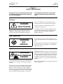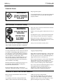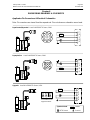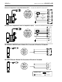
1
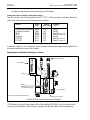
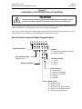
ITW Dynatec An Illinois Tool Works Company 31 Volunteer Drive Hendersonville, TN 37075 USA Telephone 615.824.3634 FAX 615.264.5222 OPERATIONS & SERVICE MANUAL #40-30 Revised 4/20/07 Adhesive Application Solutions • ISO 9001 Certified OPERATIONS AND SERVICE MANUAL MOD-PLUSTM ELECTRIC HOT MELT ADHESIVE APPLICATOR HEADS For an online copy of this manual, go to www.itwdynatec.com/manuals.htm IMPORTANT ! - READ ALL INSTRUCTIONS BEFORE OPERATING THIS EQUIPMENT It is the customer’s responsibility to have all operators and service personnel read and understand this information. Contact your ITW Dynatec customer service representative for additional copies. NOTICE! Please be sure to include the serial number of your application system each time you order replacement parts and/or supplies. This will enable us to send you the correct items that you need. ITW Dynatec Service Parts Direct Dial: 1-800-538-9540 ITW Dynatec Technical Service Direct Dial: 1-800-654-6711 Moving Forward Through Technology™ ITW Dynatec c. 1999 MOD-PLUS ELECTRIC HEAD Manual #40-30 Revised 3/99 SAFETY INSTRUCTIONS GENERAL CONSIDERATIONS SERVICING EQUIPMENT q Read and follow these instructions. Failure to do this could result in severe personal injury or death. 1. Only trained personnel are to operate and service this equipment. q 2. Additional safety instructions and/ or symbols are located throughout this manual. They serve to warn maintenance personnel and operators about potentially hazardous situations. Never service or clean equipment while it is in motion. q Inspect the machine for unsafe conditions daily and replace all worn or defective parts. q Keep work area uncluttered and well lit. q All covers and guards must be in place Shut off the equipment and lock out all input power at the source before attempting any maintenance. 3. SIGNS 1. Read and obey all of the warning labels, signs and caution statements on the equipment. 2. Do not remove or deface any of the warning labels, signs and caution statements on the equipment. 3. Replace any warning labels, signs and caution statements which have been removed or defaced. Replacements are available from ITW Dynatec. before operating this equipment. For precautions and definitions of safety symbols, refer to the Safety Chapter of the service manual. Follow the maintenance and service instructions in the manual. ADDITIONAL CONSIDERATIONS ITW Dynatec An Illinois Tool Works Company Adhesive Application Solutions 1. To ensure proper operation of the equipment, use specified electrical and/ or air supply sources. 2. Do not attempt to alter the design of the equipment unless written approval is received from ITW Dynatec. 3. Keep all manuals readily accessible at all times and refer to them often for the best performance from your equipment. Page iii Revised 6/04 ITW Dynatec c. 1999 MOD-PLUS ELECTRIC HEAD Manual #40-30 TABLE OF CONTENTS Chapter - Page # Chapter 1 Safety Precautions Chapter 2 Description & Specifications Description . . . . . . . . . . . . . . . . . . . . . . . . . . . . . . . . . . . . . . . . . . . . . . . . . . . . . . . . . . . . . . . . . . . . 2-1 Specifications . . . . . . . . . . . . . . . . . . . . . . . . . . . . . . . . . . . . . . . . . . . . . . . . . . . . . . . . . . . . . . . . . . 2-2 Dimensions . . . . . . . . . . . . . . . . . . . . . . . . . . . . . . . . . . . . . . . . . . . . . . . . . . . . . . . . . . . . . . . . . . . . 2-4 Chapter 3 Installation & Start Up Handling and Shipping . . . . . . . . . . . . . . . . . . . . . . . . . . . . . . . . . . . . . . . . . . . . . . . . . . . . . . . . . . . Service Requirements . . . . . . . . . . . . . . . . . . . . . . . . . . . . . . . . . . . . . . . . . . . . . . . . . . . . . . . . . . . . Installation Instructions . . . . . . . . . . . . . . . . . . . . . . . . . . . . . . . . . . . . . . . . . . . . . . . . . . . . . . . . . . Installation Diagrams . . . . . . . . . . . . . . . . . . . . . . . . . . . . . . . . . . . . . . . . . . . . . . . . . . . . . . . . . . . . 3-1 3-1 3-1 3-2 Chapter 4 Maintenence Maintenence Schedule . . . . . . . . . . . . . . . . . . . . . . . . . . . . . . . . . . . . . . . . . . . . . . . . . . . . . . . . . . . Purging the Filter Chamber . . . . . . . . . . . . . . . . . . . . . . . . . . . . . . . . . . . . . . . . . . . . . . . . . . . . . . . Replacement of the Built-in Filter . . . . . . . . . . . . . . . . . . . . . . . . . . . . . . . . . . . . . . . . . . . . . . . . . . Nozzle Cleaning . . . . . . . . . . . . . . . . . . . . . . . . . . . . . . . . . . . . . . . . . . . . . . . . . . . . . . . . . . . . . . . . 4-1 4-2 4-2 4-3 Chapter 5 Troubleshooting & Service In General . . . . . . . . . . . . . . . . . . . . . . . . . . . . . . . . . . . . . . . . . . . . . . . . . . . . . . . . . . . . . . . . . . . . . Troubleshooting Guide . . . . . . . . . . . . . . . . . . . . . . . . . . . . . . . . . . . . . . . . . . . . . . . . . . . . . . . . . . . Replacement of the Module . . . . . . . . . . . . . . . . . . . . . . . . . . . . . . . . . . . . . . . . . . . . . . . . . . . . . . . Module Assembly Instructions (Replacement of the Piston Seal and/ or Seal Cartridge) . . . . . . . . Testing Resistance of Heater Cartridge or Temperature Sensor . . . . . . . . . . . . . . . . . . . . . . . . . . . . Replacement of the Heater Cartridge or RTD Sensor . . . . . . . . . . . . . . . . . . . . . . . . . . . . . . . . . . . Re-Assembly Procedures and General Cautions . . . . . . . . . . . . . . . . . . . . . . . . . . . . . . . . . . . . . . . 5-1 5-1 5-6 5-6 5-7 5-8 5-9 Chapter 6 Component Illustrations & Bills of Material Model Designation Guide . . . . . . . . . . . . . . . . . . . . . . . . . . . . . . . . . . . . . . . . . . . . . . . . . . . . . . . . Bill of Materials: Typical One-Port Mod-Plus Electric Applicator . . . . . . . . . . . . . . . . . . . . . . . . . Component Illustration: Typical One-Port Mod-Plus Electric Applicator . . . . . . . . . . . . . . . . . . . . Bill of Material: Mod-Plus Electric Valves & Coil Assemblies . . . . . . . . . . . . . . . . . . . . . . . . . . . . Component Illustration: Mod-Plus Electric Valves & Coil Assemblies . . . . . . . . . . . . . . . . . . . . . . 6-1 6-2 6-3 6-4 6-5 Chapter 7 Ordering Guides Mod-Plus Single Orifice Nozzles . . . . . . . . . . . . . . . . . . . . . . . . . . . . . . . . . . . . . . . . . . . . . . . . . . . Mod-Plus Multi Orifice Nozzles . . . . . . . . . . . . . . . . . . . . . . . . . . . . . . . . . . . . . . . . . . . . . . . . . . . Mod-Plus Electric Head Heater Cartridges . . . . . . . . . . . . . . . . . . . . . . . . . . . . . . . . . . . . . . . . . . . Mod-Plus Electric Head RTD Sensors . . . . . . . . . . . . . . . . . . . . . . . . . . . . . . . . . . . . . . . . . . . . . . . Service Kits & Assemblies . . . . . . . . . . . . . . . . . . . . . . . . . . . . . . . . . . . . . . . . . . . . . . . . . . . . . . . . Recommended Service Parts List . . . . . . . . . . . . . . . . . . . . . . . . . . . . . . . . . . . . . . . . . . . . . . . . . . . 7-1 7-1 7-3 7-3 7-3 7-4 Page iv Revised 1/02 ITW Dynatec c. 1999 MOD-PLUS ELECTRIC HEAD Manual #40-30 Chapter 8 Engineering Drawings & Schematics DynaControl/ Dynamini Pin Connection & Schematic . . . . . . . . . . . . . . . . . . . . . . . . . . . . . . . . . . Dynaplus/Pro Pin Connection & Schematic . . . . . . . . . . . . . . . . . . . . . . . . . . . . . . . . . . . . . . . . . . Upgrade Pin Connection & Schematic . . . . . . . . . . . . . . . . . . . . . . . . . . . . . . . . . . . . . . . . . . . . . . . Electronic Temperature Control (ETC/RO) Pin Connection & Schematic . . . . . . . . . . . . . . . . . . . Microprocessor Temperature Control/ CompuVision (MCV) Pin Connection & Schematic . . . . . Electric Modules Pin Connections & Schematics . . . . . . . . . . . . . . . . . . . . . . . . . . . . . . . . . . . . . . 8-1 8-1 8-1 8-2 8-2 8-2 Page 1-1 Revised 1/07 ITW Dynatec c. 1997 ALL MODELS Chapter 1 SAFETY PRECAUTIONS All operators and service personnel must read and understand this manual before operating or servicing equipment. All maintenance and service on this equipment must be performed by trained technicians. Electrical DANGER HIGH VOLTAGE Dangerous voltages exist at several points in this equipment. To avoid personal injury, do not touch exposed connections and components while input power is on. Disconnect, lockout and tag external electrical power before removing protective panels. A secure connection to a reliable earth ground is essential for safe operation. A disconnect switch with lockout capability must be provided in the line ahead of the unit. Wiring used to supply electrical power should be installed by a qualified electrician. High Temperatures WARNING HOT SURFACE Severe burns can occur if unprotected skin comes in contact with molten adhesive or hot application system parts. Safety glasses, gloves and long- sleeved clothing must be worn whenever working with or around adhesive application systems. High Pressure WARNING HIGH PRESSURE PRESENT To avoid personal injury, do not operate the equipment without all covers, panels and safety guards properly installed. To prevent serious injury from molten adhesive under pressure when servicing the equipment, disengage the pumps and relieve the adhesive system’s hydraulic pressure (e.g., trigger the heads, hand-held applicators, and/or other application devices into a waste container) before opening any hydraulic fittings or connections. IMPORTANT NOTE: Even when a system’s pressure gauge reads “0” psig, residual pressure and trapped air can remain within it causing hot adhesive and pressure to escape without warning when a filter cap or a hose or hydraulic connection is loosened or removed. For this reason, always wear eye protection and protective clothing. Either of the two High Pressure symbols shown may be used on equipment. Page 1-2 Revised 3/97 ITW Dynatec c. 1997 ALL MODELS Protective Covers WARNING DO NOT OPERATE WITHOUT GUARDS IN PLACE Keep all guards in place! To avoid personal injury, do not operate the application system without all covers, panels and safety guards properly installed. Eye Protection & Protective Clothing WARNING EYE PROTECTION REQUIRED PROTECTIVE CLOTHING REQUIRED It is very important that you PROTECT YOUR EYES when working around hot melt adhesive equipment! Wear safety glasses with side shields which conform to ANSI Z87.1 or EN166. Failure to wear safety glasses could result in severe eye injury. It is important to protect yourself from potential burns when working around hot melt adhesive equipment. Wear protective gloves and long-sleeved, protective clothing to prevent burns that could result from contact with hot material or hot components. Always wear steel-reinforced safety shoes. Safe Installation and Operation To avoid possible failure of hoses, make sure all hoses are routed to avoid kinking, tight radius turns (8” or less) and abrasive contact. Hot-melt hoses should not have prolonged contact with heat-absorbing surfaces such as cold floors or metal troughs. These heat-absorbing surfaces can alter adhesive flow and cause incorrect calibration. Hoses should never be covered with materials that prevent heat dissipation, such as insulation or sheathing. Read this manual before applying electrical power to the equipment. Equipment may be damaged by incorrect electrical connections. Do not use adhesive that is dirty or that may be chemically contaminated. Doing so can cause system clogging and pump damage. When adhesive hand-held applicators or other movable applicators are used, never point them at yourself or at any other person. Never leave a hand-held applicator’s trigger unlocked when not actually in use. Do not operate the hopper or other system components without adhesive for more than 15 minutes if the temperature is 150 degrees C (300 degrees F) or more. To do so will cause charring of the residual adhesive. Never activate the heads, hand-held applicators and/ or other application devices until the adhesive’s temperature is within the operating range. Severe damage could result to internal parts and seals. Treatment for Burns From Hot Melt Adhesives Burns caused by hot melt adhesive must be treated at a burn center. Care should be used when working with hot melt adhesives in the molten state. Because they rapidly solidify, they present a unique hazard. Even when first solidified, they are still hot and can cause severe burns. When working near a hot melt application system, always wear safety gloves, safety glasses and long-sleeved, protective clothing. Page 1-3 Revised 1/07 ITW Dynatec c. 1997 ALL MODELS Always have first-aid information and supplies available. Call a physician and/or an emergency medical technician immediately. Service Refer all servicing to qualified personnel only. Explosion/ Fire Hazard Never operate this unit in an explosive environment. Use cleaning compounds recommended by ITW Dynatec or your adhesive supplier only. Flash points of cleaning compounds vary according to their composition, so consult with your supplier to determine the maximum heating temperatures and safety precautions. Lockout/ Tagout Follow OSHA 1910.147 (Lockout/ Tagout Regulation) for equipment’s lockout procedures and other important lockout/ tagout guidelines. Be familiar with all lockout sources on the equipment. Even after the equipment has been locked out, there may be stored energy in the application system, particularly in the capacitors within the panel box. To ensure that all stored energy is relieved, wait at least one minute before servicing electrical capacitors. Use of PUR (Polyurethane) Adhesives PUR adhesives emit fumes (MDI and TDI) that can be dangerous to anyone exposed to them. These fumes cannot be detected by the sense of smell. ITW Dynatec strongly recommends that an exhaust hood or system be installed over any PUR system. Consult with your adhesive manufacturer for specifics about required ventilation. CAUTION: Because of the nature of PUR adhesives to strongly bond in the presence of moisture, care must be taken to prevent them from curing inside Dynatec equipment. If PUR adhesive solidifies in a unit, the unit must be replaced. Always purge old PUR adhesive from the system per your adhesive manufacturer’s instructions and timetable. ALLOWING PUR ADHESIVE TO CURE IN A UNIT VOIDS ITW DYNATEC’S WARRANTY. In This Manual WARNINGS and CAUTIONS are found throughout this manual. WARNINGS mean that failure to observe the specific instructions may cause injury to personnel. CAUTIONS mean that failure to observe the specific instructions may damage the equipment. Page 1-4 Revised 3/97 ITW Dynatec An Illinois Tool Works Company Adhesive Application Solutions ITW Dynatec c. 1997 ALL MODELS Page 2-1 Revised 6/04 ITW Dynatec c. 1999 MOD-PLUS ELECTRIC HEAD Manual #40-30 Chapter 2 DESCRIPTION AND SPECIFICATIONS Description ITW Dynatec’s MOD-PLUS Electric Applicator Head is an electrically operated, single or multinozzle hot melt adhesive applicator assembly with an integrated filter cartridge that prevents particulate matter from obstructing flow through the head. It is used with intermittent adhesive pressure and constant adhesive pressure hot melt adhesive supply units (ASUs). Each Mod-Plus Electric applicator features one to four adhesive valve modules mounted to a single service block. Each module is opened and closed by an electric solenoid. Springs are used to keep the valve closed when no electric signal is supplied to the solenoid. The rate of adhesive flow from the applicator is determined by the adhesive pressure applied by the ASU’s pump and the size of the nozzle orifice. The applicator is heated by replaceable cartridge heating elements which are controlled by an integrated RTD sensor and electronic control. As seen in the illustration below, the module is mounted onto a service block. A stem inside the module is magnetically triggered by a solenoid, which allows adhesive to flow through the module. The heated adhesive supply hose may be connected at the rear of the service block or at the top. Adhesive flows from the hose into and through the channels within the block to the module. An electric signal opens the adhesive valve, allowing adhesive to flow through the module’s nozzle when the valve is open. Three standard Mod-Plus Electric applicators, supporting one to four modules, are available. Each model can be configured for either ITW Dynatec’s DynaControl or Dynamini controller, Dynaplus/ Dynapro systems, Microprocessor Temperature Control/CompuVision (MCV) or Electronic Temperature Control with Readout (ETC/RO), or it can be configured for a competitive upgrade. Water-resistant models are available for all of these configurations. Solenoid Supply Hose Inlet Solenoid Connection Service Block Electric Module Supply Hose Inlet Filter Cap Stem Three standard Mod-Plus Electric modules are available: a high-speed DC version, a high-viscosity DC version and a 120 VAC version. See the valve specifications for the performance characteristics of each valve. Purge Set Screw Module Opening Filter EZ Nozzle Filter Purge Drain The Mod-Plus Electric Module Page 2-2 Revised 6/04 ITW Dynatec c. 1999 MOD-PLUS ELECTRIC HEAD Manual #40-30 Specifications Environmental: Storage/ shipping temperature . . . . . . . . . . . . . . . . . . . . . . . . . . . . . . -40°C to 70°C (-40°F to 158°F) Ambient service temperature . . . . . . . . . . . . . . . . . . . . . . . . . . . . . . . . -7°C to 50°C (20°F to 122°F) Physical: Dimensions . . . . . . . . . . . . . . . . . . . . . . . . . . . . . . . . . . . . see dimensional layout on following page Weight . . . . . . . . . . . . . . . . . . . . . . . . . . . . . . . . . . . . . . Model 0441: 0.68 to 2.05 kg (1.5 to 4.5 lb.) Mounting . . . . . . . . . . . . . . . . . . . . . . . . . . . . . . . . M5x .8 screws with insulators or 1/2” rod mount, insulated clamps, 12 to 13 mm rod Performance: Temperature range . . . . . . . . . . . . . . . . . . . . . . . . . . . . . . . . . . . . . . 38°C to 218°C (100°F to 425°F) Warm-up time . . . . . . . . . . . . . . . . . . 20 minutes for cold start/ 10 minutes for module change only Adhesive pressure range Standard High-Speed DC module: 69 bar maximum (1000 psi maximum) . . . . . . . . . . . . . . . . . . . Optional High-Viscosity DC module: 69 bar maximum (1000 psi maximum) . . . . . . . . . . . . . . . . . . . . . . . . . . . . . . . . Optional AC module: 48 bar maximum (700 psi maximum) Maximum Cycle Rate Maximum Viscosity Standard Module 106144 Standard Module 106144 High Visc. Module 108750 6000 cps 12000 cps NA VL-1 Driver D 6000 cps 12000 cps NA 1000 cyc. per min. continuous only NA 120 VAC NA NA 6000 cps NA NA 600 cyc. per min. Coil Power Supply ILD-2 Driver C AC Module 109017 High Visc. Module 108750 6000 cyc. per 600 cyc. min. at 1200 . or less per min. cps . Maximum Flow Rate Coil Power Supply C ILD-2 Driver VL-1 Driver 120 VAC D Standard Module 106144 A High Visc. Module 108750 B AC Module 109017 A AC Module 109017 NA Minimum Open/Closed Time Standard Module 106144 High Visc. Module 108750 AC Module 109017 650cc/ min. 600cc/ min. NA @ 1000 cps @ 6000 cps 4/ 6 ms 50/ 50 ms NA 650cc/ min. @1000 cps 600cc/ min. @6000 cps NA 30/ 30 ms continuous only NA NA NA 650cc min. NA @1000 cps NA 50/ 50 ms Table Notes: A. Maximum flow at 6000 cps is 350cc/ min. B. Maximum flow at 12000 cps is 230cc/ min. C. Each ILD-2 Driver can power up to eight modules. D. Each VL-1 Driver can power one module. Page 2-3 Revised 2/04 ITW Dynatec c. 1999 MOD-PLUS ELECTRIC HEAD Manual #40-30 Electrical: Applicator supply voltage . . . . . . . . . . . . . . . . . . . . . . . . 120 VAC or 200-240 VAC/ 1p/ 50-60 Hz Module supply voltage . . . . . . . . . . . . . . . . . . . . . . . . . . . . . . . ITW-Dynatec supplied valve driver Module Power requirements . . . . . . . . . . . . . . . . . . . . . . 120 VAC module = 125 w max./ module . . . . . . . . . . . . . . . . . . . . . . . . . . . . . . . . . . . . . . . . . DC module/ VC-1 driver = 80 w max./ module . . . . . . . . . . . . . . . . . . . . . . . . . . . . . . . . . . . . . . . . . DC module/ ILD-2 driver = see ILD-2 manual Applicator Power requirements: Model BF0441 BF0662 BF1104 No. Modules 1 2 4 Spacing Between Nozzle Centers --44 mm 25 mm Wattage 120 VAC 240VAC 200 240 360 200 400 585 Page 2-4 Revised 2/05 ITW Dynatec c. 1999 MOD-PLUS ELECTRIC HEAD Manual #40-30 Dimensions Model No. BF0441 BF0662 BF0652 BF0472 BF1104 WIDTH A B 44mm n.a. 1.73” 66mm 44mm 2.6” 1.73” 65mm 38mm 2.56” 1.50” 47mm 25mm 1.732” .984” 109.9mm 25mm 4.33” .984” 119 mm 4.7” 95 mm 3.74” 54 mm 2.13” BF0441 BF0652 108 mm 4.25” 81 mm 3.2” B A A BF0662 B A BF0472 B A BF1104 B A ITW Dynatec c. 1999 MOD-PLUS ELECTRIC HEAD Manual #40-30 Page 3-1 Revised 1/02 Chapter 3 INSTALLATION & START UP Note: Re-read Chapter 1 “Safety Precautions” before performing any installation or start-up procedures. All installation and start-up procedures must be performed by qualified, trained technicians. Handling and Shipping MOD-PLUSÔ Electric applicator head assemblies are packaged within protective cushioning material in a fiber packing carton. This package may be shipped inside another carton along with other individual boxes containing components of the system. Service Requirements The applicator assembly consists of a service block and one or two modules. Incoming electrical power and temperature control for the applicator head is supplied through the flexible cable exiting the adhesive supply hose cuff. The applicator has a circular, plastic connector which mates with the connector attached to this cable. Incoming (operating) electrical power for the module is supplied either through a valve driver, a timer, or a customer-supplied power source. See the installation diagrams on the following pages for configuration. Driver Requirements See Specifications (Ch. 2) for ITW drivers/ electric modules performance comparisons. Installation Instructions The applicator head has been tested at the factory and is ready for installation and operation. Electric valve drivers are triggered by ITW Dynatec-supplied or customer-supplied 24 VDC timers or limit switches which sense the position of the package or object to which adhesive is being applied. Refer to your valve driver manual for specific installation instructions. Switches should be mounted on moveable brackets to provide adjustment for proper location of adhesive application. Refer to the installation diagram on the following page for location of components referred to in the cont. following section. Page 3-2 Revised 6/04 ITW Dynatec c. 1999 MOD-PLUS ELECTRIC HEAD Manual #40-30 Configuration for ILD-2 Driver Configuration for VL-1 Driver ILD-2 Driver ILD-2 detail of bottom connectors MPC-2 Timer MPC-2 Timer, TPC-2 Timer or DPC-2 Timer Power Cord Cable 106012 Customersupplied 24VDC Signal Customersupplied 24VDC Signal Cable 106012 Cable 106011 Cable 106011 Cable 106018 for additional 4 valve expansion box or single valve direct connect 4 Valve Expansion Box 106020 Cables: 1m - 110169 4m - 110172 2m - 110170 5m - 110173 3m - 110171 Solenoid Electrical Connection VL-1 Low Voltage Driver Cables: 1m - 110169 4m - 110172 2m - 110170 5m - 110173 3m - 110171 Adhesive Supply Hose Applicator Electrical Connection Rod Mount Bracket or Adhesive Inlet Module Solenoid Module Body Filter Nut Nozzle Filter Purge Drain Installation Diagram Using ILD-2 or VL-1 Driver 90° 45° hose fitting hose fitting Page 3-3 Revised 6/04 ITW Dynatec c. 1999 MOD-PLUS ELECTRIC HEAD Manual #40-30 Configuration for 120 VAC Power Supply Customer-supplied 120VAC Signal Cable 109019 (5’) 109020 (10’) 109021 (15’) Solenoid Electrical Connection Adhesive Supply Hose Applicator Electrical Connection Rod Mount Bracket or Adhesive Inlet Module Solenoid Module Body Filter Nut Nozzle Filter Purge Drain Installation Diagram Using 120VAC Power Supply 90° 45° hose fitting hose fitting Page 3-4 Revised 6/04 ITW Dynatec c. 1999 MOD-PLUS ELECTRIC HEAD Manual #40-30 1. The applicator should be supported from brackets that permit lateral and vertical adjustments. Mount the applicator on a 12mm to 13mm rod or bracketry using 5mm screws and insulators provided. Allow access to the filter. For proper application, the maximum distance from the nozzle tip to the substrate should not exceed 6.4mm (1/4 inch). 2. Before making the adhesive connection to the applicator, align the adhesive supply hose with its electrical connector oriented in relation to the electrical connector on the top of the applicator. Connect the swivel fitting of the hot melt hose to the adapter on the service block, using either the inlet port located above the filter nut or the port located on the top of the applicator (behind the applicator electrical connection in the diagram). When tightening the hose fitting, hold the hose cuff to prevent the hose core from rotating. 3. Make the electrical connection from the hose to the applicator by connecting the female connector of the hose to the male connector of the applicator. 4. Make the electrical connection from the driver, timer, or other power source to the solenoid by connecting the female connector of the driver’s extension cable to the male connector of the solenoid. 5. It is advisable to check the temperature of the applicator. This can be done through the temperature readout of the adhesive supply unit. Surface temperature may be checked with a separate pyrometer and surface probe or with a dial thermometer. Turn the system power switch ON. Permit the applicator to warm up at least 20 minutes (10 minutes for module change) before reading temperature. 6. Purge the applicator of air and oil, using the following procedure:. WARNING HIGH PRESSURE During the purging procedure, hot adhesive and oil can come out of the head under high pressure. Wear safety glasses, gloves and protective clothing. WARNING Use a stable, deep container to collect hot-melt adhesive and/ or oil. a. Turn the applicator ON. Allow adhesive and applicator to warm up. b. Remove the nozzle from the module by loosening the nozzle cap. Place a heat resistant container under the module to collect the material that drains from the applicator c i. If equipped with a VL-1 Driver, timer, or other power source: Energize the solenoid by manually energizing the timer output or power source. or ii. If equipped with the ILD-2 Driver: Energize the solenoid by toggling the channel switch on the ILD-2 to the “test” position. 7. Replace nozzle, orienting the nozzle tip so it points toward the substrate. Page 4-1 Revised 6/04 ITW Dynatec c. 1999 MOD-PLUS ELECTRIC HEAD Manual #40-30 Chapter 4 MAINTENENCE Note: Re-read Chapter 1 “Safety Precautions” before performing any maintenance procedures. All maintenance procedures must be performed by qualified, trained technicians. The MOD-PLUS Electric applicator requires no regular maintenance. Wipe the applicator clean of adhesive with a clean cloth while still hot at the end of each shift. Inspect the applicator periodically as outlined in the following table. Maintenence Schedule ITEM CHECK FREQUENCY ACTION Adhesive supply hose fitting connection Inspect for leaks As required Tighten if loose Nozzle performance Inspect all nozzles for proper operation As required Clean nozzle or re-adjust stroke limiter Filter Drain Purge chamber to remove contaminants Weekly Open drain Built-in filter Inspect for cleanliness Monthly or as required by use Replace filter element Page 4-2 Revised 6/04 ITW Dynatec c. 1999 MOD-PLUS ELECTRIC HEAD Manual #40-30 Purging the Filter Chamber WARNING HIGH PRESSURE During the purging procedure, hot adhesive can come out of the applicator under high pressure. Wear safety glasses, gloves and protective clothing. The applicator should be at operating temperature. Turn the ASU’s pump/ motor OFF. 1. Place a heat-resistant container under the purge drain. 2. With a 5mm hex key (allen wrench), slowly loosen the purge screw (do not try to remove it) and allow the adhesive and residues to flow out of applicator. Be sure to stand clear since there may be residual adhesive pressure in the applicator. Back View of Electric Head 3. Turn on the pump/ motor. When all the contaminants have run out and the glue is clean, re-tighten the screw. Replacement of the Built-in Filter Observe the same warning and conditions as in “Purging the Filter Chamber”, above. The applicator should be at operating temperature. Turn the ASU’s pump/ motor OFF. Retaining Screw (do not remove) Filter Cap Purge Drain Hole Purge Screw (not seen, under head) 1. Place a heat-resistant container under the purge drain. 2. With a 5mm hex key (allen wrench), slowly loosen the purge screw and allow the adhesive to flow out of applicator. Stand clear since there may be residual adhesive pressure in the applicator. 3. Remove the filter cap with an open wrench and replace the filter element. CAUTION: Apply a coat of anti-seize compound onto the threads of the filter cap before re-installing it. 4. Re-install the filter cap slowly, taking care to seat the cap o-ring without pinching it. Page 4-3 Revised 12/01 ITW Dynatec c. 1999 MOD-PLUS ELECTRIC HEAD Manual #40-30 Nozzle Cleaning Occasionally nozzles can become clogged with char, residue or other foreign material. This can result in the decrease or even loss of glue flow. ITW Dynatec has three nozzle cleaning kits available, which are orifice-size specific: PN 101877 PN 101878 PN 101879 Nozzle Cleaning Kit: 0.010 to 0.017 orifice Nozzle Cleaning Kit: 0.018 to 0.027 orifice Nozzle Cleaning Kit: 0.028 to 0.040 orifice WARNING HIGH PRESSURE Before using the nozzle cleaning kit: Turn OFF the ASU, then slowly open the head’s purge drain to relieve adhesive pressure. The nozzle must be at operating temperature when cleaned. Turn the ASU OFF. If the ASU is equipped with a piston pump, remove the air pressure from the pump. Purge the residual adhesive pressure in the head using the filter drain. Remove the nozzle retaining nut and nozzle with a 14mm open wrench. Use the reamers in the kit to clear the orifice. Carefully insert the reamer into the tip of the nozzle. Since there are several orifice sizes available, first make sure that the reamer is compatible with the orifice size you are about to clean. CAUTION: If a reamer of too large a diameter is used to clean the orifice, it could result in a broken reamer jammed in the nozzle, or damage to the nozzle itself. Page 4-4 Revised 1/02 ITW Dynatec An Illinois Tool Works Company Adhesive Application Solutions ITW Dynatec c. 1999 MOD-PLUS ELECTRIC HEAD Manual #40-30 Page 5-1 Revised 6/04 ITW Dynatec c. 1999 MOD-PLUS ELECTRIC HEAD Manual #40-30 Chapter 5 TROUBLESHOOTING & SERVICE Note: Re-read Chapter 1 Safety Precautions” before performing any troubleshooting or repair procedures. All troubleshooting or repair procedures must be performed by qualified, trained technicians. In General If failure occurs, first verify the following: 1. all the electrical connections are made properly, 2. the ASU’s main power switch is ON, 3. the pump is ON, 4. the drivers are connected properly and have power, 5. the temperature controller is in operation and the setpoints are correct for the application, and 6. all components are heating properly. Note: If the Mod-Plus Electric valve was installed on the applicator without the coil in place, or if the coil has been removed for several minutes, then the adhesive in the pressure tube may be partially solidified. After installing the coil, allow approximately ten minutes for the adhesive in the pressure tube to re-melt before attempting to energize the valve. Troubleshooting Guide Section One: Head Temperature Troubleshooting Problem Possible Cause Solution Applicator does not reach operating temperature 1. Temperature setpoint is too low. 1. Check setpoints and adjust as necessary. See ASU manual. 2. Inoperative heater cartridge. 2. Check heater and heater connections. Replace heater if necessary; see instructions in this chapter. 3. Inoperative temperature sensor. 3. Check sensor and sensor connections. Replace sensor if necessary; see instructions in this chapter. 1. Applicator temperature setpoint is too high. 1. Check setpoints and adjust as necessary. See ASU manual. 2. Inoperative temperature sensor. 2. Check sensor and sensor connections. Replace sensor if necessary; see instructions in this chapter. Applicator is too hot Page 5-2 Revised 6/04 ITW Dynatec c. 1999 MOD-PLUS ELECTRIC HEAD Manual #40-30 Troubleshooting Guide, cont. Section Two: Adhesive Bead Size and Pattern Corrections Problem Possible Cause Solution Adhesive output too low. (Bead size too small) 1. Adhesive pressure is too low. 1. Raise adhesive pressure. See ASU manual. 2. Nozzle orifice is too small 2. Change to a larger orifice nozzle. for the application. 3. Nozzle is partially clogged. 3.Clean or replace nozzle. See Ch. 4. 4. Filter is dirty. 4. Change or clean filter. See Ch. 4. 5. System temperatures are too low for the adhesive in use. 5. Correct system temperatures. See ASU manual. Adhesive output too high. (Bead size too large) 1. Adhesive pressure is too high. 1. Reduce adhesive pressure. See ASU manual. 2. Nozzle orifice is too large for the application. 2. Change to a smaller orifice nozzle. Adhesive output is OK, but pattern is erratic or inconsistent. 1. Adhesive pressure is too low. 1. Raise adhesive pressure. See ASU manual. 2. Nozzle is partially clogged. 2.Clean or replace nozzle. See Ch. 4. 3. Triggering device (photo eye, proximity switch, etc.) is out of alignment or malfunctioning. 3. Check and correct as necessary. 4. Timer settings are incorrect or timer is malfunctioning. 4. Check and correct as necessary. cont. Page 5-3 Revised 1/02 ITW Dynatec c. 1999 MOD-PLUS ELECTRIC HEAD Manual #40-30 Problem Pattern registration (timing) is incorrect Possible Cause Solution 6. If using the VL-1 driver: total cycle rate or “ontime” may be out of range. 6. The minimum “on-time” for the VL-1 is 30 ms; the minimum total cycle time is 60 ms. If the application is outside this range, the ILD-2 driver must be used. See the VL-1 manual for more information. 1. Triggering device (photo eye, proximity switch, etc.) is out of alignment. 1. Check device and adjust as necessary. 2. Pattern compensation (offset) is incorrect. 2. Adjust pattern compensation. Note: If the Mod-Plus Electric head has replaced an existing pneumaticallyoperated head, the pattern compensation programmed for the pneumatic head will likely be incorrect for the Mod-Plus Electric head. The Mod-Plus Electric valve reacts much faster than a pneumatic valve, and usually requires very little, if any, compensation in the timer. Page 5-4 Revised 6/04 ITW Dynatec c. 1999 MOD-PLUS ELECTRIC HEAD Manual #40-30 Troubleshooting Guide, cont. Section Three: No Adhesive Output from Valve for modules PN 106144 and PN 108750 only • Check for plugged nozzle. First, check the following areas and correct if necessary Verify that driver is receiving input signal from timing device as follows: • For ILD-2: Open door and observe the green input LED. It should be lit. • For VL-1: Remove the cover and observe the green input LED. It should be lit. • Check for dirty filter. • Check for proper system temperatures. No problems found • Check adhesive level in hopper. • Check adhesive pressure. Correct problem, allow system to stabilize, then re-test applicator. Driver is receiving signal No signal • Check connections between driver and timing device. Problem found Verify signal output from driver as follows: • Check timing devices for proper operation. • Check triggering device for proper adjustment and operation. • For ILD-2: Open door and observe the yellow output LED. It should be lit. • Check electrical connections between driver and coil. Signal output present • For ILD-2: Check if input and output cables are connected to the same channel. No signal output from ILD-2 • For VL-1: Check that adhesive viscosity and cycle rates are within the limits listed on page 2-2. Valve still does not operate • Disconnect the 7-pin coil connector from the driver. Measure the resistance between pins 5 and 7 on the coil connector. With the applicator hot, this reading should be 12-14 ohms. • Now measure the resistance between pins 5 or 7 and pin 4. This reading should be infinite (i.e. no continuity). Coil fails test • Verify that driver is plugged in and power switches are ON. • Check that the channel switch is in the “Run” position. • Check the fuses. Signal output now present • Allow ten minutes after coil replacement for adhesive in pressure tube to melt. • Check that coil is fully seated on the valve and adjustment nut is snug. No signal output Driver is not operating properly. Replace driver and re-test applicator. Coil passes test Replace coil and re-test applicator. No signal output from VL-1 Driver is not operating properly. Replace driver and re-test applicator. Valve is now operating Check coil as follows: • For VL-1: Remove the cover and observe the yellow output LED. It should be lit. Test applicator for proper operation. Valve is now operating Valve still does not operate Valve is not operating properly. Replace valve and re-test applicator. Page 5-5 Revised 1/06 ITW Dynatec c. 1999 MOD-PLUS ELECTRIC HEAD Manual #40-30 Troubleshooting Guide, cont. Section Four: No Adhesive Output from Valve for module PN 109017 only First, check the following areas and correct if necessary No problems found • Check for plugged nozzle. • Check for dirty filter. • Check for proper system temperatures. • Check adhesive level in hopper. • Check adhesive pressure. Problem found Correct problem, allow system to stabilize, then re-test applicator. • Check connections between driver and timing device. • Check timing devices for proper operation. • Check triggering device for proper adjustment and operation. Valve still does not operate Valve is now operating Check coil as follows: • Disconnect the 7-pin coil connector from the driver. Measure the resistance between pins 1 and 2 on the coil connector. With the applicator hot, this reading should be in the range of 100-130 ohms. • Now measure the resistance between pins 1 or 2 and pin 4. This reading should be infinite (i.e. no continuity). Coil fails test Coil passes test Replace coil and re-test applicator. • Allow ten minutes after coil replacement for adhesive in pressure tube to melt. • Check that coil is fully seated on the valve and adjustment nut is snug. Test applicator for proper operation. Valve is now operating Valve still does not operate Valve is not operating properly. Replace valve and re-test applicator. Page 5-6 Revised 1/07 ITW Dynatec c. 1999 MOD-PLUS ELECTRIC HEAD Manual #40-30 Replacement of the Module Turn the ASU OFF. Turn all adhesive pressure OFF. WARNING HIGH PRESSURE During the purging procedure, hot adhesive can come out of the applicator under high pressure. Wear safety glasses, gloves and protective clothing. 1. Place a heat-resistant container under the manifold. 2. With a 5mm hex key (allen wrench), slowly loosen the purge screw and allow the adhesive to flow out of applicator. Be sure to stand clear since there may be residual adhesive pressure in the applicator. 3. Remove the module from the service block by removing the two shoulder bolts on the front of the module with a 4mm hex key screwdriver (allen wrench). Make sure that the old o-ring located on the back of the module is also removed (the new module will include a new o-ring). 4. Mount the new module onto the service block and tighten the screws (15 in-lb maximum).. Module Assembly Instructions Use the component illustration and parts list on pages 6-8 and 6-9 as a reference with the following instructions for the Mod-Plus Electric module. ITW Dynatec’s Module Renew Kit (see Chapter 7) contains all needed items to renew one module. CAUTION: Use care when handling the module pressure tube and stem which contain thin-walled components. Do not use pliers, clamps, a vice, etc. on these parts. CAUTION: IT IS IMPORTANT not to mix parts from more than one module during the rebuilding process. Doing so would cause the stroke settng to be incorrect, which could cause improper operation of the module. For this reason, ONLY ONE MODULE SHOULD BE REBUILT AT A TIME. 1. Coat o-rings with a liberal amount of High Temp Lube (PN N07588). CAUTION: DO NOT SUBSTITUTE! Failure to use High Temp Lube (N07588) may result in premature seal breakdown and leakage of glue from the applicator. 2. Check that o-ring grooves are clean and free of adhesive. Install o-rings (items 13 & 14 on page 6-5) into stem seat assembly, taking care to ensure that o-rings are in good condition, with no visible nicks or cuts. 3. Install o-ring (item 14) into the stem seat assembly, placing it into the middle (of three) grooves (see cross-section on page 6-9). 4. Install the stem seat assembly (item 16) onto module body (item 12) using the four M3 screws cont. (item 7) provided. ITW Dynatec c. 1999 MOD-PLUS ELECTRIC HEAD Manual #40-30 Page 5-7 Revised 1/07 5. Coat the ball end of the stem (item 6) with High Temp Lube (N07588). 6. Install the stem through the module body and into the seat, engaging the o-ring in the seat. 7. Place the spring (item 4) in the recess at the top of the stem. 8. Place pressure tube and flange assembly over the needle and seat the pin in the body into the hole in the flange. Attach with the M3 screws provided. CAUTION: The pressure tube must be bottomed into the flange before assembly to prevent binding the needle. 9. Re-attach module to the head with two shoulder screws. 10. Place the solenoid over the pressure tube and twist until it drops down onto the flange. 11. Thread lock nut (item 2) onto pressure tube. To disassemble, reverse above order. Testing of Heater Cartridge or Temperature Sensor 1. Turn the ASU OFF and make sure all adhesive air pressure and the pump are turned OFF. 2. Unplug the electrical cable from the adhesive supply hose to expose the pins in the cable. Note: Pin connectors and pinout numbers will vary depending on the control scheme of the applicator. See Ch. 8 for a diagram of each. Testing Resistance of the Heater Cartridge a. The resistance value (Ohms) of your heater cartridge may be obtained from the chart below, or it may be calculated using the formula: (to determine wattage, see chart on pg. 7-3) 120 VAC 200-240 VAC 240 VAC Volts 2 = Ohms Watts Ohms Watts Ohms Watts Ohms Watts 200 72 400 144 220 b. For DynaControl or Dynamini: With an 240 60 ohmmeter, contact pins 7 and 8 and measure resistance. For Dynaplus/Pro: With an ohmmeter, contact pins 8 and 9 and measure resistance. For ETC/RO or MCV: With an ohmmeter, contact pins 3 and 5 and measure resistance. For Upgrade: With an ohmmeter, contact pins 1 and 2 and measure resistance. 245 c. A tolerance range of ± 5% is allowed. A heater cartridge that tests outside of this range must Page 5-8 Revised 1/02 ITW Dynatec c. 1999 MOD-PLUS ELECTRIC HEAD Manual #40-30 be replaced. Replacement instructions follow in this chapter. Testing Resistance of the RTD Temperature Sensor The values listed in the following chart are at 25°C (77°F).Check the sensor’s resistance at the connector pins listed in the chart for the appropriate controller. Control Sensor Type Ohms @ 25°°C (77°°F) Connector Pins DynaControl/Dynamini DynaPro/DynaPlus MCV MCV Upgrade ETC/RO ETC/RO Pt100 Pt100 Pt100 Pt100 N120 NiFe NiFe 110 110 110 110 138 100 100 5 and 6 2 and 3 6 and 10 (sensor 1) 8 and 12 (sensor 2) 3 and 5 6 and 10 (sensor 1) 8 and 12 (sensor 2) A tolerance range of ± 5% is allowed. A sensor that tests outside of this range must be replaced. Replacement instructions follow in this chapter. Replacement of Heater Cartridge or Sensor Pin Connector* Cover Plate Set Screw Gasket Heater Cartridge (in a horizontal port) *DynaControl/Dynamini model shown Ground Wire RTD Sensor (3 ports) Heater/ RTD Sensor Replacement Diagram ITW Dynatec has a High Temp Heater Splice Kit available (PN 102645). Each kit contains sufficient connectors and shrink tube to replace a heater cartridge (the heater is ordered separately). ITW Dynatec c. 1999 MOD-PLUS ELECTRIC HEAD Manual #40-30 Page 5-9 Revised 1/02 1. Disconnect power to the ASU and make sure all adhesive pressure is purged and pumps are turned OFF. 2. Disconnect the electrical cable assembly from the hose. 3. Remove the wire access cover plate and the gasket via two holding screws. 4. Cut the wires of the heater cartridge (or sensor) at the splice. 5. Pull the heater (or sensor) out of the service block. 6. Apply a thin coat of thermal paste (PN 001V061) to the new cartridge heater (or new sensor). 7. Put new cartridge heater (or new sensor) in service block. Connect wires with splice and shrink tube. 8. Replace access cover plate and gasket. Re-Assembly Procedures and General Cautions Unless noted, head re-assembly is simply the reverse sequence of the disassembly procedures. However, the following “cautions” should be followed (whenever they apply) for proper re-assembly: CAUTION: In general, all O-RINGS AND SEALS must be replaced whenever hot-melt equipment is re-assembled. All new o-rings must be lubricated with o-ring lube (PN N07588). CAUTION: TAPERED PIPE THREADS are found on air line fittings used with the pump air supply and on the outlet filter manifold. Apply thread sealant (PN N02892) whenever tapered pipe threaded parts are re-assembled. CAUTION: SOME FITTINGS used for adhesive on hot melt equipment have straight threads and o-ring seals. Use of thread sealant is not necessary with these parts, but the o-ring seals should be clean and lubricated. Tighten straight-threaded parts and fittings until their shoulders are firmly seated. Excessive torque may damage straight-threaded parts and the use of power wrenches is not recommended. CAUTION: HOT-MELT RESIDUE must be cleaned from parts before they are re-assembled, particularly from threaded parts. As a precaution against adhesive residue preventing proper re-assembly, threaded parts must always be re-tightened at operating temperature. Page 5-10 Revised 1/02 ITW Dynatec An Illinois Tool Works Company Adhesive Application Solutions ITW Dynatec c. 1999 MOD-PLUS ELECTRIC HEAD Manual #40-30 Page 6-1 Revised 3/05 ITW Dynatec c. 1999 MOD-PLUS ELECTRIC HEAD Manual #40-30 Chapter 6 COMPONENT ILLUSTRATIONS & BILLS OF MATERIAL WARNING All parts must be periodically inspected and replaced if worn or broken. Failure to do this can affect equipment’s operation and can result in personal injury. The following pages provide exploded-view reference drawings to assist users of Mod-Plus Electric modular applicators to identify parts and aid in servicing the equipment. Note: most common nuts, bolts and fasteners can be obtained locally at your hardware store. Specialty fasteners are available by contacting Dynatec’s Customer Service. Mod-Plus Electric Applicator Model Designation Guide BFXXXXXXXX 0 4 41 E D1S Dyna BF Applicator 0 6 62 A P2 CM3 Service Block Length: measured in mm Number of Modules Options: S = No Options/ Standard DC Module W = Water-resistant D E N Applicator Voltage: 1 = 120 AC 2 = 240 AC 3 = 200 AC Control Scheme: D = DynaControl P = Dynapro or Dynaplus M = MTC or CompuVision E = ETCRO N = Upgrade Module Type: E = Electric, DC coil A = Electric, AC coil C = Electric, AC coil, water resistant D = Electric, DC coil, water resistant H = Electric, High Viscosity, DC Page 6-2 Revised 12/04 ITW Dynatec c. 1999 MOD-PLUS ELECTRIC HEAD Manual #40-30 Bill of Materials for a Typical 1 Port Mod-Plus Electric Applicator Item No. 1 2 3 4 5 6 7 8 9 10 11 12 13 14 15 16 17 18 19 20 21 22 23 24 25 26 27 28 29 30 31 32 33 34 Part Number 106144, 108750 or 109017 110183 110184 101625 101624 101628 103347 103466 101833 104852 102447 101620 101618 104129 L14899 103467 104521 104523 104526 800223 104528 104127 104522 104524 104527 104525 104529 101622 103733 N00753 101627 N04268 078C088 -- -- -N01756 048J271 N00695 N01124 N00196 N00186 N07830 N07831 103085 N00181 -- -- -N00179 109551 Description Electric Module Assembly, DC Electric Module Assembly, High Viscosity, DC Electric Module Assembly, 120VAC Electric Module Assembly, DC Electric Module Assembly, 120VAC Fitting Plug Fitting Adapter with Ring M3-5 x 8mm Screw Identification Plate Service Block, BF0441 10-32 x 1/2 Tamper Proof Screw (retaining screw) M10-1.5 x 12 Cone, Relief Screw M5 x 25 SHC Screw Filter Cap, BF Head Filter, 150 micron (optional) Mounting Clamp Insulator, Mounting Clamp Cable Assembly for DynaControl 240v Cable Assembly for DynaControl 120v Cable Assembly for DynaPlus/Pro Cable Assembly for ETC/RO Cable Assembly for MCV Cable Assembly for Upgrade (assy. includes sensor) Cable Assembly for DynaControl 240v/ Washdown Cable Assembly for DynaControl 120v/ Washdown Cable Assembly for DynaPlus/Pro/ Washdown Cable Assembly for ETC/ Washdown Cable Assembly for MCV/ Washdown Cable Assembly for Upgrade (assy. includes sensor)/ Washdown Gasket, Wire Access Wire Access Cover Plate 1/8 NPT Level Seal Plug M3-.5 x 6 Phillips Head Screw Terminal Ring Washer #4 Heater (see ordering guide on pg. 7-3) Parallel Connector Shrink Tube Lock Washer #10 1/16 NPT Level Seal Plug O-ring 111 O-ring 019 M3-5 x 4, Flat Point Socket Head Set Screw 90° Swivel Fitting (optional) 45° Swivel Fitting (optional) O-ring 014 Temperature Sensor (see ordering guide on pg. 7-3) O-ring, -012 Cable Entry Plug Qty. 1 1 1 4 1 1 1 1 2 1 1 1 1 1 1 1 1 1 1 1 1 1 1 1 1 2 1 2 1 1 1 1 2 0.13 ft. 2 1 1 1 2 1 1 1 1 1 Page 6-3 Revised 2/03 ITW Dynatec c. 1999 MOD-PLUS ELECTRIC HEAD Manual #40-30 23 22 Pin 7 Red 21 Pin 8 Orange RTD 32 Pin 5 & 6 Brown Ground 14 Cable Assembly Detail for DynaControl/Dynamini Pin Green/Yellow 9 14 24 20 19 18 12 1 17 17 32 13 2 15 4 31 25 25 5 30 28 3 6 26 29 23 15 16 4 22 21 28 34 27 33 8 7 German Sensor in top hole. US Sensor in lower hole. Component Illustration: Typical 1 port Mod-Plus Electric Applicator (DynaControl/Dynamini version illustrated) 11 10 Page 6-4 Revised 12/04 ITW Dynatec c. 1999 MOD-PLUS ELECTRIC HEAD Manual #40-30 Bill of Materials for a Typical 2 PORT Mod-Plus Electric Applicator Item No. 1 2 3 4 5 6 7 8 9 10 11 12 13 14 15 16 17 18 19 20 21 22 23 24 25 26 27 28 29 30 31 32 33 34 Part Number 106144, 108750 or 109017 110183 110184 101625 101624 101628 103347 104261 110377 101833 104852 102447 101620 101618 104129 L14899 103467 104521 104523 104526 800223 104528 104127 104522 104524 104527 104525 104529 101622 103733 N00753 101627 N04268 078C088 -- -- -N01756 048J271 N00695 N01124 N00196 N00186 103470 N07831 103085 N00186 -- -- -N00179 109551 Description Electric Module Assembly, DC Electric Module Assembly, High Viscosity, DC Electric Module Assembly, 120VAC Electric Module Assembly, DC Electric Module Assembly, 120VAC Fitting Plug Fitting Adapter with Ring M3-5 x 8mm Screw Identification Plate Service Block, BF0662 Service Block, BF0472 (1” Centers) 10-32 x 1/2 Tamper Proof Screw (retaining screw) M10-1.5 x 12 Cone, Relief Screw M5 x 25 SHC Screw Filter Cap, BF Head Filter, 150 micron (optional) Mounting Clamp Insulator, Mounting Clamp Cable Assembly for DynaControl 240v Cable Assembly for DynaControl 120v Cable Assembly for DynaPlus/Pro Cable Assembly for ETC/RO Cable Assembly for MCV Cable Assembly for Upgrade (assy. includes sensor) Cable Assembly for DynaControl 240v/ Washdown Cable Assembly for DynaControl 120v/ Washdown Cable Assembly for DynaPlus/Pro/ Washdown Cable Assembly for ETC/ Washdown Cable Assembly for MCV/ Washdown Cable Assembly for Upgrade (assy. includes sensor)/ Washdown Gasket, Wire Access Wire Access Cover Plate 1/8 NPT Level Seal Plug M3-.5 x 6 Phillips Head Screw Terminal Ring Washer #4 Heater (see ordering guide on pg. 7-3) Parallel Connector Shrink Tube Lock Washer #10 1/16 NPT Level Seal Plug O-ring 111 O-ring 019 M3-5 x 4, Flat Point Socket Head Set Screw 90° Swivel Fitting (optional) 45° Swivel Fitting (optional) O-ring 019 Temperature Sensor (see ordering guide on pg. 7-3) O-ring, -012 Cable Entry Plug Qty. 2 1 1 4 1 1 ‘ 1 1 2 1 1 1 1 1 1 1 1 1 1 1 1 1 1 1 1 2 1 2 1 1 1 1 2 0.13 ft. 2 3 1 1 2 1 1 1 1 1 Page 6-5 Revised 2/03 ITW Dynatec c. 1999 MOD-PLUS ELECTRIC HEAD Manual #40-30 23 22 21 Pin 7 Red Pin 8 Orange RTD 32 Pin 5 & 6 Brown Ground 14 Cable Assembly Detail for DynaControl/Dynamini Pin Green/Yellow 9 24 14 20 19 18 12 1 17 17 32 13 2 15 4 31 25 25 5 25 30 28 6 3 26 29 23 22 15 16 4 34 27 28 33 21 7 8 German Sensor in top hole. US Sensor in lower hole. Component Illustration: Typical 2 Port Mod-Plus Electric Applicator (DynaControl/Dynamini version illustrated) 11 10 Page 6-6 Revised 12/04 ITW Dynatec c. 1999 MOD-PLUS ELECTRIC HEAD Manual #40-30 Bill of Materials for a Typical 4 PORT Mod-Plus Electric Applicator Item No. 1 2 3 4 5 6 7 8 9 10 11 12 13 14 15 16 17 18 19 20 21 22 23 24 25 26 27 28 29 30 31 32 33 34 Part Number 106144, 108750 or 109017 110183 110184 101625 101624 101628 103347 109470 101833 104852 102447 101620 101618 104129 L14899 103467 104521 104523 104526 800223 104528 104127 104522 104524 104527 104525 104529 101622 103733 N00753 101627 N04268 078C088 -- -- -N01756 048J271 N00695 N01124 N00196 N00186 103470 N07831 103085 N00186 -- -- -N00179 109551 Description Electric Module Assembly, DC Electric Module Assembly, High Viscosity, DC Electric Module Assembly, 120VAC Electric Module Assembly, DC Electric Module Assembly, 120VAC Fitting Plug Fitting Adapter with Ring M3-5 x 8mm Screw Identification Plate Service Block, BF1104 10-32 x 1/2 Tamper Proof Screw (retaining screw) M10-1.5 x 12 Cone, Relief Screw M5 x 25 SHC Screw Filter Cap, BF Head Filter, 150 micron Mounting Clamp Insulator, Mounting Clamp Cable Assembly for DynaControl 240v Cable Assembly for DynaControl 120v Cable Assembly for DynaPlus/Pro Cable Assembly for ETC/RO Cable Assembly for MCV Cable Assembly for Upgrade (assy. includes sensor) Cable Assembly for DynaControl 240v/ Washdown Cable Assembly for DynaControl 120v/ Washdown Cable Assembly for DynaPlus/Pro/ Washdown Cable Assembly for ETC/ Washdown Cable Assembly for MCV/ Washdown Cable Assembly for Upgrade (assy. includes sensor)/ Washdown Gasket, Wire Access Wire Access Cover Plate 1/8 NPT Level Seal Plug M3-.5 x 6 Phillips Head Screw Terminal Ring Washer #4 Heater (see ordering guide on pg. 7-3) Parallel Connector Shrink Tube Lock Washer #10 1/16 NPT Level Seal Plug O-ring 111 O-ring 019 M3-5 x 4, Flat Point Socket Head Set Screw 90° Swivel Fitting (optional) 45° Swivel Fitting (optional) O-ring 019 Temperature Sensor (see ordering guide on pg. 7-3) O-ring, -012 Cable Entry Plug Qty. 4 1 1 4 1 1 1 1 2 1 1 1-2 1-2 1 1 1 1 1 1 1 1 1 1 1 1 2 1 2 1 1 1 1 2 0.13 ft. 2 3 1 1 2 1 1 1 1 1 Page 6-7 Revised 2/03 ITW Dynatec c. 1999 MOD-PLUS ELECTRIC HEAD Manual #40-30 23 22 21 Pin 7 Red Pin 8 Orange RTD 9 32 Pin 5 & 6 Brown Ground 14 Cable Assembly Detail for DynaControl/Dynamini Pin 24 Green/Yellow 9 24 14 12 18 13 19 20 12 1 17 17 13 32 15 2 31 4 25 25 5 25 30 6 28 3 26 29 21 22 15 16 28 34 27 33 23 11 7 8 4 German Sensor in top hole. US Sensor in lower hole. Component Illustration: Typical 4 Port Mod-Plus Electric Applicator (DynaControl/Dynamini version illustrated) 10 ITW Dynatec c. 1999 MOD-PLUS ELECTRIC HEAD Manual #40-30 Page 6-8 Revised 1/07 Bill of Materials: PN 109017 High-Speed Mod Plus Electric Valve & Coil Assembly, 120VAC Bill of Materials: PN 106144 High-Speed Mod Plus Electric Valve & Coil Assembly, DC Bill of Materials: PN 108750 High-Viscosity Mod Plus Electric Valve & Coil Assembly, DC Bill of Materials: PN 110183 (Water Resistant, High Speed DC) & 110184 (W.R 120Vac) Part Number Item No. 1 2 3 4 5 6 7 8 9 10 11 12 13 14 15 Description 109016 106144 108750 109016 109014 104418 109013 108746 109836 108745 L09219 L18038 104414 108748 108747 N00181 N00175 108743 106136 104425 106139 104418 104423 108746 109836 108745 L09219 L18038 104414 108748 108747 N00181 N00175 108743 106136 104425 108744 104418 104423 108746 108740 108745 L09219 L18038 104414 108748 108747 N00181 N00175 108743 106136 110183 109775 106139 104418 104423 108746 109836 108745 L09219 L18038 104414 108748 108747 N00181 N00175 108743 106136 Qty. 110184 109776 109014 104418 109013 108746 109836 108745 L09219 L18038 104414 108748 108747 N00181 N00175 108743 106136 Coil Mod Plus Electric Valve Assm. Coil Nut Compression Spring, Needle Flange, Pressure Tube Needle Assembly M3-5 x 8mm SHC Screw Nozzle Nut Mod Plus Mounting Screw Pressure Tube Electric Valve Body Assembly Electric Valve Body O-ring, -014 O-ring, -008 Roll Pin Seat Assembly 1 1 1 1 1L 1 8 1 2 1 1 1 2 2 1 1 Page 6-9 Revised 1/07 ITW Dynatec c. 1999 MOD-PLUS ELECTRIC HEAD Manual #40-30 3 10 5 4 6 1 7 12 14 13 9 11 12 Placement of #13 o-ring (in the middle groove) 13 15 Cross-section of PN 106136 Stem Seat Assembly 7 8 Component Illustration: Assembly 106144 or 108750 Mod-Plus Electric Module 2 Page 6-10 Revised 1/03 ITW Dynatec An Illinois Tool Works Company Adhesive Application Solutions ITW Dynatec c. 1999 MOD-PLUS ELECTRIC HEAD Manual #40-30 Page 7-1 Revised 5/07 ITW Dynatec c. 1999 MOD-PLUS ELECTRIC HEAD Manual #40-30 Chapter 7 ORDERING GUIDES Mod-Plus Single Orifice Nozzles Part Number EZ-style Part Number Button-style Orifice Diameter Orifice Length 100706 100707 100709 100710 100711 100712 100713 100714 L19965 L19966 L19967 L19968 L19969 L19970 L19971 L19972 .25mm (0.010 inch) .30mm (0.012 inch) .38mm (0.015 inch) .51mm (0.020 inch) .64mm (0.025 inch) .76mm (0.030 inch) .89mm (0.035 inch) 1.02mm (0.040 inch) 1.27mm (0.050 inch) 1.27mm (0.050 inch) 1.91mm (0.075 inch) 1.91mm (0.075 inch) 1.91mm (0.075 inch) 1.91mm (0.075 inch) 1.91mm (0.075 inch) 1.91mm (0.075 inch) Mod-Plus Multi-Orifice Nozzles Part Number L09350-1015 L09350-1022 L09350-1030 L09350-1045 L09350-1060 L09350-1090 L09350-1515 L09350-1522 L09350-1530 L09350-1545 L09350-1560 L09350-1590 L09350-2015 L09350-2022 L09350-2030 L09350-2045 L09350-2060 L09350-2090 L09350-2515 L09350-2522 L09350-2530 L09350-2545 L09350-2560 L09350-2590 # of Orifices Orifice Diameter 2 2 2 2 2 2 2 2 2 2 2 2 2 2 2 2 2 2 2 2 2 2 2 2 Angle .25mm (0.010 inch) .25mm (0.010 inch) .25mm (0.010 inch) .25mm (0.010 inch) .25mm (0.010 inch) .25mm (0.010 inch) .38mm (0.015 inch) .38mm (0.015 inch) .38mm (0.015 inch) .38mm (0.015 inch) .38mm (0.015 inch) .38mm (0.015 inch) .51mm (0.020 inch) .51mm (0.020 inch) .51mm (0.020 inch) .51mm (0.020 inch) .51mm (0.020 inch) .51mm (0.020 inch) .64mm (0.025 inch) .64mm (0.025 inch) .64mm (0.025 inch) .64mm (0.025 inch) .64mm (0.025 inch) .64mm (0.025 inch) 15° 22° 30° 45° 60° 90° 15° 22° 30° 45° 60° 90° 15° 22° 30° 45° 60° 90° 15° 22° 30° 45° 60° 90° cont. Page 7-2 Revised 1/02 ITW Dynatec c. 1999 MOD-PLUS ELECTRIC HEAD Manual #40-30 Mod-Plus Multi-Orifice Nozzles, cont. Part Number L09350-3015 L09350-3022 L09350-3030 L09350-3045 L09350-3060 L09350-3090 L09276-1015 L09276-1022 L09276-1030 L09276-1045 L09276-1515 L09276-1522 L09276-1530 L09276-1545 L09276-2015 L09276-2022 L09276-2030 L09276-2045 L09276-2515 L09276-2522 L09276-2530 L09276-2545 L09276-3015 L09276-3022 L09276-3030 L09276-3045 L10382-10 L10382-15 L10382-20 L10382-25 # of Orifices 2 2 2 2 2 2 3 3 3 3 3 3 3 3 3 3 3 3 3 3 3 3 3 3 3 3 4 4 4 4 Orifice Diameter Angle .76mm (0.030 inch) .76mm (0.030 inch) .76mm (0.030 inch) .76mm (0.030 inch) .76mm (0.030 inch) .76mm (0.030 inch) .25mm (0.010 inch) .25mm (0.010 inch) .25mm (0.010 inch) .25mm (0.010 inch) .38mm (0.015 inch) .38mm (0.015 inch) .38mm (0.015 inch) .38mm (0.015 inch) .51mm (0.020 inch) .51mm (0.020 inch) .51mm (0.020 inch) .51mm (0.020 inch) .64mm (0.025 inch) .64mm (0.025 inch) .64mm (0.025 inch) .64mm (0.025 inch) .76mm (0.030 inch) .76mm (0.030 inch) .76mm (0.030 inch) .76mm (0.030 inch) .25mm (0.010 inch) .38mm (0.015 inch) .51mm (0.020 inch) .64mm (0.025 inch) 15° 22° 30° 45° 60° 90° 15° 22° 30° 45° 15° 22° 30° 45° 15° 22° 30° 45° 15° 22° 30° 45° 15° 22° 30° 45° all quads are 35° inner angle, 76° outer angle. Page 7-3 Revised 6/04 ITW Dynatec c. 1999 MOD-PLUS ELECTRIC HEAD Manual #40-30 Mod-Plus Electric Head Heater Cartridges (12.5 mm diameter) # of Modules/ Model 200-240VAC Part Number Description 120VAC Part Number Description 1 Module/ BF0441 2 Modules/ BF0662 4 Modules/ BF1104 104128 (240v) 104249 104251 104254 104255 104257 220w x 33mm 400w x 55mm 585w x 99mm 200w x 33mm 240w x 55mm 360w x 99mm Mod-Plus Electric Head RTD Sensors Control Part Number DynaControl/Dynamini Dynaplus/Pro MTC/ CompuVision ETC Upgrade N07958 N07958 N07958 N08176 N07864 Quantity 1 1 2 2 1 Description Pt100 Pt100 Pt100 NiFe N120 Service Kits & Assemblies High-Speed & High Viscosity Module Renew Kit PN 106141 Contains all the parts necessary to renew one module, including spring, module-attaching screws, coil nut, seal lubricant, o-rings and instructions. Replacement DC Coil Assembly PN 106140 Replacement AC Coil Assembly PN 109034 Replacement DC Water-resistant Coil Assembly PN 110185 Replacement AC Water-resistant Coil Assembly PN 110186 Contains a coil and coil nut. Replacement High-Speed Valve Assembly PN 106139 Replacement High-Viscosity Valve Assembly PN 108750 Replacement AC Valve Assembly PN 109014 Contains a complete valve assembly, without the coil. Nozzle Cleaning Kits Three nozzle cleaning kits are available, sized to be orifice-specific: PN 101877 Nozzle Cleaning Kit .010 to .017 orifice PN 101878 Nozzle Cleaning Kit .018 to .027 orifice PN 101879 Nozzle Cleaning Kit .028 to .040 orifice High Temp Splice Kit PN102645 This kit consists of a foot of shrink tube and nine connectors (splices). The kit will enable you to replace the heater or sensor in one applicator. ITW Dynatec c. 1999 MOD-PLUS ELECTRIC HEAD Manual #40-30 Page 7-4 Revised 1/07 Recommended Service Parts List Part Number Description See Ordering Guide, pg. 7-3 N00196 N00186 N00181 102645 101618 Heater RTD Sensor O-ring 111 O-ring 019 O-ring 014 High Temp Heater Splice Kit Filter, 100 micron (standard) 106141 N00181 N00175 104418 L18038 106137 104423 108689 -- -- High-Speed Module Renew Kit, consists of: O-ring 014 O-ring 008 Coil Nut Module Mounting Screw SHC Screw, M3-0.5x8 Needle Spring Seal Lube, 1/4 oz. Instruction Sheet 1 per module 2 2 1 2 8 1 1 1 109033 N00181 N00175 104418 L18038 106137 109013 108689 -- -- 120VAC Module Renew Kit, consists of: O-ring 014 O-ring 008 Coil Nut Module Mounting Screw SHC Screw, M3-0.5x8 Needle Spring Seal Lube, 1/4 oz. Instruction Sheet 1 per module 2 1 1 2 8 1 1 1 See Ordering Guide, pg. 7-3 Qty. 1 1 1 1 1 1 2 Page 8-1 Revised 3/99 ITW Dynatec c. 1999 MOD-PLUS ELECTRIC HEAD Manual #40-30 Chapter 8 ENGINEERING DRAWINGS & SCHEMATICS Applicator Pin Connectors & Electrical Schematics Note: Pin connectors are viewed from the exposed end. Pins not shown on schematics are not used. DynaControl/Dynamini Uses PN N07958 RTD Sensor, Pt100. 5 6 7 Upgrade 3 9 8 Dynaplus/Pro 4 1 VVV 2 7 8 5 6 9 Uses PN N07958 RTD Sensor, Pt100. 1 2 3 4 5 6 7 8 9 1 2 3 VVV 8 9 Uses PN N07864 RTD Sensor, N120. VVV 5 4 2 6 3 1 Note: pin out numbers are not labeled on the Upgrade connector. Symbols Used: RTD Sensor 1 2 3 5 6 VVV Heater Ground Page 8-2 Revised 1/02 ITW Dynatec c. 1999 MOD-PLUS ELECTRIC HEAD Manual #40-30 Electronic Temperature Control with Readout (ETC) 1 2 Uses two PN N08176 RTD Sensors, NiFe. 3 5 6 8 10 12 3 6 VVV 7 4 5 8 9 10 11 Blue/ White Blue 12 13 14 Blue/ White Blue 13 Microprocessor Temperature Control or CompuVision (MCV) 1 2 3 5 VVV 3 6 Uses two PN N07958 RTD Sensors, Pt100. 6 8 7 4 5 8 9 10 11 12 13 14 10 12 13 PN 106144 & 108750 Electric Module Pin Connector & Electrical Schematic 1 3 4 5 2 4 6 5 7 solenoid 7 PN 109017 Electric Module Pin Connector & Electrical Schematic 1 3 4 6 4 1 2 5 7 solenoid 2 Symbols Used: RTD Sensor VVV Heater Ground