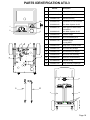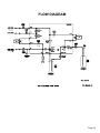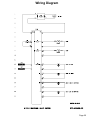
1
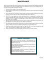
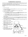
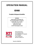
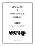
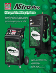
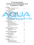
OPERATION MANUAL
ATX-3
Automatic Transmission Fluid Exchanger
WARNING
DO NOT pour anything except new
transmission fluid into the fill port.
Serious damage will result.
The ATX-3 must be connected to a
FULLY CHARGED 12 volt battery. This
should be the battery in the vehicle being
serviced.
Do not use a battery charger to power
the ATX-3.
Use of undercharged batteries and
battery chargers will damage the ATX-3
and void the warranty.
RTI Technologies, Inc
10 Innovation Drive
York, PA 17402 USA
800-468-2321
www.rtitech.com
Manual P/N 035-81321-00
TABLE OF CONTENTS
Component Description . . . . . . . . . . . . . . . . . . . . . . . . 2
Safety Precautions . . . . . . . . . . . . . . . . . . . . . . . . . . . 3
Keypad Functions . . . . . . . . . . . . . . . . . . . . . . . . . . . . 4
Cooler Mode
Connecting to the Transmission System . . . . . . . . 6
Flush . . . . . . . . . . . . . . . . . . . . . . . . . . . . . . . . . . . . 8
Drain Pan . . . . . . . . . . . . . . . . . . . . . . . . . . . . . . . . 8
Fluid Exchange . . . . . . . . . . . . . . . . . . . . . . . . . . . . 9
-1/2 Quart . . . . . . . . . . . . . . . . . . . . . . . . . . . . . . . . 9
+1/2 Quart . . . . . . . . . . . . . . . . . . . . . . . . . . . . . . . . 9
Disconnecting from the Transmission System . . . 10
Dipstick Mode
Connecting to the Transmission System . . . . . . .
Drain Pan . . . . . . . . . . . . . . . . . . . . . . . . . . . . . . .
Fluid Exchange . . . . . . . . . . . . . . . . . . . . . . . . . . .
-1/2 Quart . . . . . . . . . . . . . . . . . . . . . . . . . . . . . . .
+1/2 Quart . . . . . . . . . . . . . . . . . . . . . . . . . . . . . . .
11
12
12
13
13
Empty Used . . . . . . . . . . . . . . . . . . . . . . . . . . . . . . . .
Empty New . . . . . . . . . . . . . . . . . . . . . . . . . . . . . . . .
Maintenance . . . . . . . . . . . . . . . . . . . . . . . . . . . . . . .
Calibration . . . . . . . . . . . . . . . . . . . . . . . . . . . . . . . . .
Calibration of a Load Cell . . . . . . . . . . . . . . . . . . . . .
Parts Identification . . . . . . . . . . . . . . . . . . . . . . . . . . .
Flow Diagram . . . . . . . . . . . . . . . . . . . . . . . . . . . . . . .
Wiring Diagram . . . . . . . . . . . . . . . . . . . . . . . . . . . . .
EC Declaration of Conformity for Machinery . . . . . . .
14
14
15
16
17
18
19
20
21
Calibration - A Good Practice
The ATX-3 is the most accurate of all transmission fluid exchange equipment due to the
advanced load cell technology designed into the unit.
Most operating problems are usually fixed by performing a simple calibration procedure.
A good practice is to periodically calibrate the ATX-3 to ensure optimum performance.
Precision calibration weight(s) are included with the ATX-3.
Page 1
COMPONENT DESCRIPTION
Unpack all components. Use laminated placard to verify fitting adapter quantities.
Contact RTI if any items are missing or damaged.
12 INCH HOSE ADAPTER
(STRAIGHT)
12 INCH HOSE ADAPTER
(90°)
Quick Coupler
560-80414-00
Large Dip Tube Hose
Small Dip Tube Hose
FITTING ADAPTER SET
KEYPAD
PRESSURE GAUGE
NEW - USED SIGHT BOWLS
(FILTERS)
FILL PORT
8 FT BLACK HOSE
10 FT RED HOSE
10 FT BLACK HOSE
NEW FLUID
SIGHT INDICATOR
560-80414-00
USED FLUID
SIGHT INDICATOR
Page 2
Safety Precautions
WARNING:
Failure to follow these precautions can result in serious
injury or death.
• Read and understand the Operation Manual completely before operating this unit.
• Always wear proper eye and skin protection when operating and maintaining this equipment.
•
Take precautions to keep clothing, hair, hands, hoses etc. away from all moving parts of the vehicle.
• Many Automatic Transmission systems can be extremely hot and operate at high pressures. Always
use extreme caution when connecting and dis-connecting hoses and adapters.
• Always keep a fire extinguishing device nearby when working with flammable liquids.
• Choose a well ventilated work area and avoid breathing any harmful fumes when performing a
transmission fluid exchange.
• Check engine oil level and coolant level. Refill if low. Do not perform the exchange if either is low.
• Flush solutions are combustible and are harmful or fatal if swallowed. If swallowed call doctor
immediately and do not induce vomiting. If Flush Solution gets in eyes flush with water immediately.
For contact with skin wash with soap and water. Apply skin lotion if necessary to sooth irritation.
•
Immediately clean up any transmission fluid spills and use proper container for disposal.
• Comply with local, state, and federal regulations for fluid disposal.
•
Material Safety Data Sheets (MSDS) must be obtained on all chemicals and placed in a shop file
for reference.
IMPORTANT
Check transmission fluid level according to manufacturer’s
instructions before connecting the ATX-3
Adjust fluid level if required
Page 3
KEYPAD FUNCTIONS
560-80414-00
The ATX-3 is an automatic transmission fluid exchanger featuring state-of-the-art electronic controls
with digital weight scales measuring the automatic transmission fluid coming into and going out of the
machine. Operation of the ATX-3 is intuitive and very easy to master.
Transmission fluid is removed from vehicle and filtered before collecting in the ATX-3
used fluid tank. When the procedure is complete, the ATX-3 buzzer will sound
continuously until the stop button is pressed. Refer to page 8 for cooler mode and
page 12 for dipstick mode for complete instructions.
Filters and exchanges the used transmission fluid in the vehicle for new from the ATX3. The procedure is complete when the buzzer sounds continuously until the stop
button is pressed. Refer to page 9 for cooler mode and page 12 for dipstick mode for
complete instructions.
Transmission fluid is emptied completely from the new fluid tank inside the ATX-3. It
can be stored in a bulk container for later use. This procedure is performed if a
change in transmission fluid types is required. The ATX-3 buzzer will sound
continuously until the stop button is pushed when procedure is complete. Refer to
page 14 for complete instructions.
Transmission fluid is emptied completely from the used fluid tank inside the ATX-3
into a bulk used tank for proper disposal. This procedure is performed when the used
fluid tank is full or the used fluid tank capacity is not sufficient to perform selected
exchange. The ATX-3 buzzer will sound continuously until the stop button is pushed
when procedure is complete. Refer to page 14 for complete instructions.
Page 4
KEYPAD FUNCTIONS
Used after the exchange process if fluid level is too high on the transmission dipstick.
Removes ½ quart of fluid from the transmission. The ATX-3 buzzer will sound
continuously until the stop button is pushed when procedure is complete. Refer to
page 9 for cooler mode and page 13 for dipstick mode for complete instructions.
Used after the exchange process if fluid level is too low on the transmission dipstick.
Adds ½ quart of transmission fluid to the transmission from the ATX-3 new fluid tank.
The ATX-3 buzzer will sound continuously until the stop button is pushed when
procedure is complete. Refer to page 9 for cooler mode and page 13 for dipstick
mode for complete instructions.
Stops any procedure the moment it is pushed, also used at the end of a procedure to
acknowledge completion of process and turn buzzer off.
Illuminates when battery connection is backwards.
Illuminates when the used tank is too full or flashes when the capacity remaining is
less than exchange amount selected. The EMPTY Used procedure must be run to
continue operation of the ATX-3.
Illuminates when the new fluid tank is empty or flashes when the new fluid level is less
than the selected exchange amount. The operator must add fluid to the new fluid tank
of the ATX-3 through the fill port.
Illuminates when the vehicle engine is running and connected properly to the ATX-3.
Illuminates when the selected process is complete. The buzzer will sound
continuously when this is illuminated.
The ATX-3 provides two modes of fluid exchange - Cooler or dipstick mode. The
mode is selected using these buttons when the ATX-3 is powered up. During dipstick
mode, the start engine button is pressed at a specified step.
Two LED readouts display the amount of fluid in the New and Used fluid tanks and
give realtime readouts as the different procedures run.
Caution: Always use fingers to operate keypad. Use of sharp objects will cause damage
and void the warranty.
Page 5
COOLER MODE
CONNECTING TO THE TRANSMISSION SYSTEM
Transmission
Cooler Lines
560-80414-00
Radiator
Fitting
Adapters
12 inch
90° Adapter Hose
12 inch
Straight Adapter Hose
IMPORTANT
Check transmission fluid level according to manufacturer’s
instructions before connecting the ATX-3
Adjust fluid level if required
1.
Add desired amount of transmission fluid to the new fluid tank through the ATX-3 fill port. Monitor
fluid level in the ATX-3 with the LED readouts or with fluid sight indicators.
2.
Locate and disconnect the transmission cooler lines at the most convenient location:
A. At cooler line connecting to radiator usually most accessible if vehicle is not on lift.
B. At clamped rubber hose connection to transmission cooler usually most accessible if vehicle
is on a lift. Cooler is most often in front of the radiator.
C. At cooler line connecting to the transmission usually requires vehicle to be on a lift.
Page 6
COOLER MODE
CONNECTING TO THE TRANSMISSION SYSTEM
3.
Select and install proper fitting adapters to disconnect points. Use closest matching adapter and
o-ring to seal any leaks if exact matching adapter can not be found. In some cases it may be
easier to use one of the open end rubber hose adapters on the disconnected male fitting on the
cooler line then to select the matching adapter.
4.
Connect 12 inch adapter hoses to fitting adapters.
5.
Connect 10 ft black and red hoses (right side of ATX-3) to the 12 inch adapter hoses.
IMPORTANT
Attempt to pull hoses apart to ensure couplers are attached properly
6.
Connect red (positive) clamp on power cable to red (positive) terminal on vehicle battery. Connect
the black (negative) clamp to a ground on vehicle frame. All lights on keypad should illuminate for
one second and buzzer should pulse. If not, check connections and make sure REVERSE
POLARITY light is not illuminated.
WARNING:
7.
Handle battery connection cable with extreme caution. Batteries generate
explosive gases during normal operation. Working in the vicinity of a lead-acid or
other automotive battery is dangerous. Wear eye protection. Never smoke or allow
a spark or flame in the vicinity of the battery. Do not connect the black power clip
to the negative post of the battery to avoid a spark.
Set the park brake and turn engine on, listen for the buzzer to sound once loudly and for the
READY light on the keypad to stay illuminated. The ATX-3 pressure gauge on the control panel
will indicate a positive pressure if the connection to the transmission is correct.
If buzzer does not sound and light does not illuminate IMMEDIATELY TURN ENGINE OFF and
switch the black and red 10 ft hoses and repeat the above.
Note: For most Chrysler and Mitsubishi vehicles the transmission pump will be functioning when
the vehicle is in “Neutral” instead of “Park”. Perform the service in Neutral gear on these
vehicles.
8.
Press the COOLER MODE button. The light on the button will illuminate.
9.
Once the ATX-3 is connected properly (READY light stays illuminated) the machine automatically
goes into circulate mode. Check hoses for heat, if circulate is working correctly both hoses should
be warm to the touch.
10. The ATX-3 pressure gauge will indicate the transmission operating pressure. Refer to the
manufacturer’s recommended pressure to determine if the transmission system is functioning
correctly.
Page 7
COOLER MODE
FLUSH
1.
Vehicle engine is running and the ATX-3 is connected as previously described, READY light is
illuminated.
2.
Slowly add Flush Solution as recommended by the supplier into the vehicle through the
transmission system dipstick port.
3.
The ATX-3 will now circulate the solution through the transmission system until a procedure is
selected. The Flush Solution will be removed from the system during the exchange procedure.
DRAIN PAN
Note:
If transmission filter is to be replaced, perform the following procedure before removing
the transmission pan. If not, skip to the next procedure.
1.
Vehicle engine is running and the ATX-3 is connected as previously described, READY light is
illuminated.
2.
Light on COOLER MODE button should be illuminated. Press the DRAIN PAN button on the
keypad.
3.
Buzzer will sound once and DRAIN PAN light will stay illuminated. If an error occurs the buzzer
will sound three times and the ATX-3 will not proceed with the procedure, check all connections.
4.
Vehicle transmission pump will empty contents of the transmission system into the ATX-3 used
fluid tank. Liquid level can be viewed through the Used Fluid Level Indicator on the left side of the
ATX-3.
5.
When vehicle pan is emptied of transmission fluid the ATX-3 will automatically switch to the
circulate mode, the buzzer will sound continuously and the PROCESS COMPLETE light will stay
illuminated until the STOP button is pressed.
6.
Turn the vehicle off IMMEDIATELY after ATX-3 buzzer sounds. The vehicle is now ready to have
the transmission pan removed.
7.
After the pan is replaced, refill the pan using the +1/2 Quart button (refer to the +1/2 QUART
section). Check the transmission dipstick periodically while refilling to reach proper level.
Note: If the ATX will not add +1/2 quart, there may not be enough fluid remaining in the
transmission to satisfy the minimum pressure requirement. To correct this situation,
stop engine. Press Empty New Fluid and manually monitor the level of fluid in the
new fluid tank. Press the Stop button after two quarts have been added to the
transmission. Restart vehicle and verify the Ready LED is illuminated. Check fluid
level in the transmission. The +1/2 Quart and -1/2 Quart procedures can be used to
adjust the level.
Caution: Do not let the engine run for more than one minute after the ATX-3 buzzer
sounds. Letting the transmission run with an empty pan for an extended amount
of time can cause serious damage to the transmission system.
Page 8
COOLER MODE
FLUID EXCHANGE (4,8,12,16,20 QUARTS)
1.
Vehicle engine is running and the ATX-3 is connected as previously described, READY light is
illuminated.
2.
Determine vehicle transmission fluid capacity from the vehicle operator or service manual.
3.
Light on COOLER MODE button should be illuminated. Press the corresponding QUART button,
always round up (for example if vehicle capacity is 6.5 quarts an 8 quart exchange would be
selected).
4.
The change of fluid can be monitored through the ATX-3 Old-New Sight Bowls. These bowls
display the new bright red fluid leaving the ATX-3 and the dirty brown to black fluid coming from
the vehicle transmission system. The color of the used should become almost equal to the new
as the exchange ends. The liquid levels can be viewed through the Level Indicators on either side
of the ATX-3 (left side for used, right side for new).
5.
When the exchange of transmission fluid is complete the ATX-3 will automatically switch to the
bypass loop, the buzzer will sound continuously and the PROCESS COMPLETE light will stay
illuminated until the STOP button is pressed.
6.
Check transmission dipstick for level. Use +1/2, -1/2 QUART buttons as required to correct fluid
level.
NOTE
Some transmission pumps may have a flow rate so low that the ATX will briefly pause (or
even stop) during the exchange process. A series of two long beeps will indicate this
condition. Accelerating the engine will usually overcome this situation and decrease the
overall time required for the exchange process.
-1/2 QUART
1.
Vehicle engine is running and the ATX-3 is connected as previously described, READY light is
illuminated.
2.
Check transmission dipstick. Light on COOLER MODE button should be illuminated. Press the 1/2 QUART button to lower the fluid level if the transmission system is overfilled.
3.
When process is complete the buzzer will sound continuously and the PROCESS COMPLETE
light will stay illuminated until the STOP button is pressed.
4.
Check transmission dipstick for appropriate level.
+1/2 QUART
1.
Vehicle engine is running and the ATX-3 is connected as previously described, READY light is
illuminated.
2.
Check transmission dipstick. Light on COOLER MODE button should be illuminated. Press the
+1/2 QUART button to raise the fluid level if the transmission system is under filled.
3.
When process is complete the buzzer will sound continuously and the PROCESS COMPLETE
light will stay illuminated until the STOP button is pressed.
4.
Check transmission dipstick for appropriate level.
Page 9
DISCONNECTING FROM THE
TRANSMISSION SYSTEM
- Caution Hoses, fitting adapters and the engine may be extremely hot. Use
extreme caution when disconnecting.
1.
Turn vehicle engine off. READY light should go off. Make sure READY light is OFF before
proceeding.
2.
Disconnect ATX-3 from the vehicle battery.
3.
Disconnect 10 ft black and red hoses from the 12 inch adapter hoses.
4.
Disconnect 12 inch adapter hoses from fitting adapters connected to the transmission system.
5.
Disconnect fitting adapters from the transmission system connection points.
6.
Reconnect cooler lines. Do not cross-thread cooler line fittings when reconnecting to the
transmission system.
7.
Start vehicle engine and check for leaks at cooler line connection points, tighten if necessary.
Vehicle transmission service is complete once transmission system is leak free.
GOOD PRACTICE
Empty used fluid tank after every exchange procedure.
Page 10
DIPSTICK MODE
CONNECTING TO THE TRANSMISSION SYSTEM
IMPORTANT
Check transmission fluid level according to manufacturer’s
instructions before connecting the ATX-3
Transmission must be up to operating temperature
Adjust fluid level if required
Dipstick
Notch
Dip Tube Hose
560-80414-00
Slide Indicator
1.
Remove transmission dipstick.
2.
Hold notched end of Dip Tube Hose even with the end of the dipstick as shown above.
3.
Position the slide Indicator so that is even with the cap end of the dipstick.
Black
Hose
560-80414-00
Slide
Indicator
Dip Tube
Hose
Quick Coupler
4.
Insert notched end of Dip Tube Hose into transmission so that the Slide Indicator is even with
the top of the dipstick port as shown above.
5.
Attach Quick Coupler to other end of Dip Tube Hose.
6.
Insert Quick Coupler into fitting on end of the black hose on the left side of the ATX-3.
Page 11
7.
Connect red (positive) clamp on power cable to red (positive) terminal on vehicle battery.
Connect the black (negative) clamp to a ground on vehicle frame. All lights on keypad should
illuminate for one second and buzzer should pulse. If not, check connections and make sure
REVERSE POLARITY light is not illuminated.
WARNING:
8.
Handle battery connection cable with extreme caution. Batteries generate
explosive gases during normal operation. Working in the vicinity of a lead-acid
or other automotive battery is dangerous. Wear eye protection. Never smoke or
allow a spark or flame in the vicinity of the battery. Do not connect the black
power clip to the negative post of the battery to avoid a spark.
Press the DIPSTICK MODE button. The light on the button will illuminate.
DRAIN PAN
Note:
If transmission filter is to be replaced, perform the following procedure before removing
the transmission pan. If not, skip to the next procedure.
1.
Light on DIPSTICK MODE button should be illuminated. Press the DRAIN PAN button on the
keypad.
3.
Buzzer will sound once and DRAIN PAN light will illuminate. If an error occurs the buzzer will
sound three times and the ATX-3 will not proceed with the procedure, check all connections.
4.
The ATX-3 will withdraw used transmission fluid into the used fluid tank. The amount can be
viewed on the used LED readout and on Used Fluid Level Indicator on the left side of the ATX-3.
5.
When all possible fluid has been withdrawn, the buzzer will sound continuously.
DIPSTICK MODE
FLUID EXCHANGE (4,8,12,16,20 QUARTS)
1.
Determine vehicle transmission fluid capacity from the vehicle operator or service manual.
2.
Light on DIPSTICK MODE button should be illuminated. Press the corresponding QUART
button, always round up (for example if vehicle capacity is 6.5 quarts an 8 quart exchange
would be selected).
3.
If the ATX-3 is unable to remove any fluid from the pan within first 30 seconds FloErr (Flow
Error) message will be displayed and process will be aborted. Check if dipstick tube is inserted
properly, to appropriate depth (see Page 11). Another reason for this message is an
insufficient amount of transmission fluid in the vehicle transmission pan.
4.
The change of fluid can be monitored through the ATX-3 dip tube hose. This hose displays the
new bright red fluid leaving the ATX-3 and the dirty brown to black fluid coming from the
vehicle transmission system. The color of the used should become almost equal to the new as
the exchange ends.
5.
The process will start, removing and then replacing as much fluid as possible. The START
ENGINE light will then illuminate.
Page 12
6.
Start the engine and then press the START ENGINE button. There will be 10 second delay
after START ENGINE button is pressed to allow the new fluid to intermix with fluid in
transmission system. After 10 seconds, the exchange will continue.
7.
There is a 10 second pause after each refill.
8.
If machine is unable tor retrieve more than 0.4 of a quart from the pan while engine is running,
the Flo Err (Flow Error) message will be displayed and process needs to be aborted. Stop the
process and refill fluid to match required level.
9.
When the exchange of transmission fluid is complete the buzzer will sound continuously and
the PROCESS COMPLETE light will stay illuminated until the STOP button is pressed.
10. Remove Dip Tube Hose and check dipstick for level. If necessary, the Dip Tube Hose can be
re-inserted and the +1/2, -1/2 QUART buttons pressed as required to correct fluid level.
-1/2 QUART
1.
Vehicle engine is running and the ATX-3 dip tube hose installed into transmission.
2.
Light on DIPSTICK MODE button should be illuminated. Press the -1/2 QUART button to lower
the fluid level if the transmission system is overfilled.
3.
When process is complete the buzzer will sound continuously and the PROCESS COMPLETE
light will stay illuminated until the STOP button is pressed.
4.
Remove dip tube hose from transmission.
5.
Insert transmission dipstick and check for appropriate level.
+1/2 QUART
1.
Vehicle engine is running and the ATX-3 dip tube hose installed into transmission.
2.
Light on DIPSTICK MODE button should be illuminated. Press the +1/2 QUART button to raise
the fluid level if the transmission system is under filled.
3.
When process is complete the buzzer will sound continuously and the PROCESS COMPLETE
light will stay illuminated until the STOP button is pressed.
4.
Remove dip tube hose from transmission.
5.
Insert transmission dipstick and check for appropriate level.
Page 13
EMPTY USED
Common for both modes
1.
Connect red (positive) clamp on ATX power cable to red (positive) terminal on vehicle battery.
Connect the black (negative) clamp to a ground on vehicle frame. Vehicle engine is turned OFF.
The ATX-3 10 ft black and red hoses must be disconnected from the transmission. READY
light is off.
2.
Place end of 8 ft black hose (left side of ATX-3) in bulk used fluid container. Attach short black
adapter hose with open end to coupler on end of 8ft black hose.
3.
Press the EMPTY USED button on the keypad.
4.
Buzzer will sound and used transmission fluid will empty from the used tank inside the ATX-3 to
the bulk container. Level can be viewed on used LED readout or through the Level Indicator on
the left side of the ATX-3.
5.
Procedure will run until used tank is completely emptied or the STOP button is pressed. If process
is allowed to run until completion (30 seconds after used fluid tank is empty), the buzzer will sound
continuously and the PROCESS COMPLETE light will stay illuminated until the STOP button is
pressed.
6.
Remove short black adapter hose on the 8 ft black hose and remove it from the bulk
used fluid container.
EMPTY NEW
Common for both modes
1.
Connect red (positive) clamp on ATX power cable to red (positive) terminal on vehicle battery.
Connect the black (negative) clamp to a ground on vehicle frame. Vehicle engine is turned OFF.
The ATX-3 10 ft black and red hoses must be disconnected from the transmission. READY
light is off.
2.
Couple any fitting adapter to the end of the 10 ft red hose (right side of ATX-3). Place end of
hose in bulk storage container for later use.
3.
Press the EMPTY NEW button on the keypad.
4.
Buzzer will sound and new transmission fluid will empty from the new tank inside the ATX-3 to the
bulk storage container. Level can be viewed through the Level Indicator on the right side of the
ATX-3.
5.
Procedure will run until new tank is completely emptied or the STOP button is pressed. If process
is allowed to run until completion (30 seconds after new fluid tank is empty), the buzzer will sound
continuously and the PROCESS COMPLETE light will stay illuminated until the STOP button is
pressed.
6.
Disconnect fitting adapter from end of the 10 ft red hose.
Page 14
MAINTENANCE
The ATX-3 will provide many years of reliable service if properly maintained. The following checklist will
ensure that the ATX-3 will run at peak efficiency and present an image to your customers that your
shop performs high tech transmission services.
1.
Use tool tray for storage of tools and adapters only.
2.
Keep the exterior surface clean. Use a mild all purpose cleaner to wipe transmission fluid and dirt
off the cabinet.
3.
Do not allow the unit to sit outside in direct sunlight or inclement weather. Excessive exposure to
sunlight or moisture will cause serious damage and will void the warranty.
4.
The ATX-3 is not intended for mobile use where the unit is transported to customer sites.
Excessive vibration will shorten component life, affect accuracy of performance and void the
warranty. If the ATX-3 needs to be transported by vehicle, remove all fluid, in both the new and
used tanks, prior to transport.
5.
Be gentle when moving the ATX-3 around the shop. Tip the unit and ease the front casters over
any obstacles such as door jams, air hoses and floor irregularities.
6.
Periodically check all internal (by lifting out the tool tray) and external hoses for leaks or excessive
wear. Any weak hoses should be replaced immediately to avoid possible injury.
7.
Check the five filter screens (Items 4 and 5 on Page 18) often to avoid any blockage that may
occur. Clean out debris or replace the filter screen if necessary.
8.
Check air pressure in rear tires periodically (should be 30 psi), add air if needed.
Calibration - A Good Practice
The ATX-3 is the most accurate of all transmission fluid
exchange equipment due to the advanced load cell technology
designed into the unit.
Most operating problems are usually fixed by performing a
simple calibration procedure.
A good practice is to periodically calibrate the ATX-3 to ensure
optimum performance.
The following pages describe the reasons for calibration and
the actual calibration procedure.
Precision calibration weight(s) are included with the ATX-3.
Page 15
ATX-3 Calibration
The ATX-3 is a high-tech, electronically controlled machine for exchanging transmission fluid. The ATX3 is connected in series with the transmission fluid flow at the cooler hose. The vehicle transmission
pump then pumps used fluid into the ATX-3 used fluid tank and the ATX-3 pumps new fluid to the
transmission from the tank of new fluid in the ATX-3. Transmission pumps vary in their flow rate from
vehicle manufacturer to manufacturer. This requires that the ATX-3 monitor the old fluid coming from
the transmission and then pump new fluid back to the transmission at the same rate.
The used and new fluid tanks in the ATX-3 each sit on a weight scale (load cell). The increasing weight
of used fluid is monitored by the electronic controller which in turn controls the speed of the ATX-3
pump which is pumping new fluid to the transmission.
So, the function of the ATX-3 is to pump new fluid into the transmission as the transmission pumps out
used fluid at a rate that will keep the transmission fluid level consistent. Not too much and not too little.
This occurs with the design of the ATX-3 in a near-perfect world. So, what is the real world?
Real world conditions must be considered:
1.
Not all new transmission fluids weigh exactly the same. They are very close.
2.
Old transmission fluids can have different weights. Very old fluid can have a lot of solids
suspended in the fluid and be very heavy.
3.
Not all transmissions pump or control the flow of fluid in the same way. Some are very slow.
Others cycle the flow of fluid off and on to the cooling lines dependent on the temperature
of the fluid. Both of these examples might make the technician think the ATX-3 is not
operating correctly because it takes so long to do the exchange. The procedure can be
speeded up by accelerating the engine to 2000 RPM during the exchange.
These real world inconsistencies are expected and therefore the add or remove ½ quart feature was
built into the ATX-3.
Slots are provided on the sides of the ATX-3 so that the technician can see the fluid levels in the tanks.
The scales next to the slots approximately indicate the number of quarts in the tanks. The only
purpose of these slots is to give the technician an idea of when the used fluid tank might need to be
emptied or how many bottles of new fluid to bring from the supply room to fill the new fluid tank.
Calibration of BOTH load cells is required when:
1.
REMOVE USED FLUID flashes and three beeps are heard when trying to select amount of fluid
to be exchanged. The level of fluid in the used fluid tank is observed to be such that the tank is not
full or would not fill to capacity during an exchange procedure. For example, 8 QUARTS is pressed
and there is obviously room in the used fluid tank to accept 10 or more quarts.
2.
ADD NEW FLUID flashes and three beeps are heard when trying to select amount of fluid to be
exchanged. For example, 8 QUARTS is pressed and more than 10 quarts of fluid can be seen in
the new fluid tank.
3.
REMOVE USED FLUID flashes continuously.
4.
ADD NEW FLUID flashes continuously.
5.
The control board is replaced for any reason.
Page 16
CALIBRATION OF LOAD CELLS
The ATX-3 has two tanks, each mounted on a load cell. One tank is for new fluid and one is for used
fluid. Each tank is permanently bolted to a load cell platform which can not be removed from the unit.
The calibration procedure below must be performed for both load cells.
Never calibrate only one load cell as an imbalance may occur and the ATX-3 will not operate
correctly.
1.
Remove the rear panel.
2.
Place end of 8 ft black hose (left side of ATX-3) in bulk used fluid container. Place any adapter
onto coupler on end of hose.
3.
Press and hold 4 QUARTS and 20 QUARTS buttons until a long beep is heard.
4.
Select which load cell is to be calibrated.
a)
Press -1/2 QUART to calibrate the used fluid load cell. REMOVE USED FLUID will be flashing
throughout the remaining steps. A short beep will be heard.
b)
Press +1/2 QUART to calibrate the new fluid load cell. ADD NEW FLUID will be flashing
throughout the remaining steps. A short beep will be heard.
The pump will run and empty the contents of the selected tank through the 8 ft black hose into the
collection container.
5.
Press the STOP button when fluid is no longer leaving the machine through the black hose and the
selected tank is empty. The pump will stop running. The 4 QUARTS will be flashing. A short beep
will be heard. Check that the tank is empty.
6.
Press the STOP button again. The 12 QUARTS will be flashing. A short beep will be heard. This
programs the minimum weight.
7.
Place two 5 kg or one 10 kg
calibration weight on the top of the
selected tank. (10 kg = 22 lbs)
8.
Press the STOP button. The 12
QUARTS will be illuminated. A short
beep will be heard. This programs the
maximum weight.
8 FT.
BLACK HOSE
10 kg
Remove calibration weight(s) and
replace rear cover.
10. Press the STOP button again. A short
beep will be heard. The machine
returns to regular operating mode.
NEW
FLUID
TANK
USED
FLUID
TANK
COUPLER
ADAPTER HOSE
WITH OPEN END
COLLECTION
CONTAINER
560-80414-00
9.
CALIBRATION WEIGHT
LOAD CELLS
Page 17
PARTS IDENTIFICATION ATX-3
Part No.
5a
1
2
1
024-80119-00
Keypad Overlay
2
024-80121-00
Circuit Board (12VDC)
3
300-80075-00
Manifold Assembly
4
026-80250-00
Sight Glass 1/4" FPT w/screen
026-80248-00
Filter Mesh Cylinder 80 SS
026-80247-00
026-80248-00
Glass Sight 3/8" Barb Plastic
w/clear Bowl
Filter Mesh Cylinder 80 SS
5a
300-80028-00
Pressure Gauge
6
021-80164-00
Deck Fill Assembly ATX
7
022-80111-00
Pressure Switch
4-6 psig SPST
8
300-80033-00
Pump Gear .33 GPM 12VDC
9
300-80014-00
Hose Assembly Straight
10
300-80015-00
Hose Assembly 90 Degree
11
300-80038-00
New Fluid Tank Assembly
12
300-80040-00
Used Fluid Tank Assembly
13
031-80002-00
Load Cell 35 Kg
14
300-80074-00
Pump Assembly Diaphragm
5
5
6
4
8
Description
14
10
11
12
13
560-80414-00
9
Page 18
FLOW DIAGRAM
Page 19
Wiring Diagram
Page 20
EC Declaration of Conformity for Machinery
Directive 98/37/EC
RTI Technologies, Inc.
10 Innovation Drive
York, Pennsylvania 17402 USA
Phone: 717-840-0678
Herewith declares that:
-
ATX-3 Transmission Fluid Exchange Machine
-
is in conformity with the provisions of the Machinery Directive (directive
98/37/EC) and with the national implementing legislation
-
is in conformity with the provisions of the following other EC directives:
Electromagnetic Compatibility (EMC) Directive 89/336/EEC
Electromagnetic Emissions EN 61000-6-4: 2001
Electromagnetic Immunity EN 61000-6-2: 1999
The ATX-3 was tested and certified to the EMC Directive by:
TÜV America Inc.
1775 Old Highway 8 NW Ste. #104
New Brighton, MN 55112
Phone: 651-638-0262
Thomas L. Crandall
Vice President - Technology
Dated: January 17, 2007
Page 21