1
SECTION
J
FRONT SUSPENSION
3.8
CCE))
TYPE
GRAND TOURING MODELS
INDEX
Page
J.4
Data
J.5
J,5
Wishbones and ahti-roll bar
J.5
Front hydraulìc damper
J.5
J.5
J.6
J.6
Flont Suspension Assernbly
J7
Removal of fulcrum shaft
Adjustment of the ball joint
Renewing the rubber/steel bushes
J.
l0
J.tI
Adjustment of the balljoint
J.l
t
J.l
l
J.tz
J,l2
INDEX
þontinued)
Dismantling
Bearing end-float adjustment . .
Hydraulic Dampers
I.t4
1.14
J.l5
Renewing the link arm bushes
J.15
J.15
Torsion Bar Adjustment
J.l5
Castor Angle
Adjustment
J.t7
Camber Angle
Adjustment
Accielental Damage
{
I
-.
I
a
I
!
1
J.
l8
J.19
FRONT
SUSPENSION
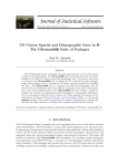
DESCRIPIÏON
The right and left hancl front suspension units are comprised of the upper and lower wishbones to which
are
attached the stub axle carriers, the torsion bars and the hydraulic dampers.
The torsion bars are attached at their forward end to the lower wishbones and at the rear end to brackets secured
to the chassis frame,
Each torsion bar is controlled by a telescopic direct acting hydraulic damper.
The top of each damper is attached to brackets formed on the forward chassis assembly; the bottom of the damper
being bolted to the lower wishbone.
The upper wishbone is a one piece forging secured to the threaded fulcrum shaft by means of pinch bolts through
clamps formed on the wishbone inner mounting. The fulcrum shaft is mounted on two rubber/steel bonded bushes,
*
*'i
Fig.
Page J.4
L
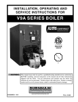
The
front suspension
assembl¡',
FRONT SUSPENSION
The outer ends of the wishbone carry the upper wishbone ball joint which is in turn secured to the hub carrier
by the tapered shank of the balt pin and a locknut.
The lower lvishbone is a two piece assembly the inner ends of which are mounted at the fulcrum shaft end on
rubber/steel bonded bushes.
The outer end of the lower wishbone is secured to the lower wishbone ball joint by the tapered shank of the
ball pin and a locknut.
An anti-roll bar fitted between the lower lvishbones is attached to the
chassis
front member by rubber insulated
brackets,
The wheel hubs are supported on two tapered roller bearings, of which the ir.rner races
a tapered hole bored in the stub axle carrier.
D
fit on a shaft located in
ATA
Typ"
Independent torsion bars
Dampers
Telescopic hydraulic
Castor Angle
l¡1'+ot-" positive
Canrber Angle
f'_þf" positive
Swivel inclination
4"
ROUTINE
MAINTENANCE
Wishbones and,A.nti-Rolt Bar
The front suspension wishbone levers and the
anti-roll bar are supported on rubber bushes which
do not require any attention.
Front Hydraulic Darnpers
I
.l
The front hydraulic dampers are of tl.re telescopic
type, and no replenishment rvith fluid is necessary
or provided for.
;
I
EVERY 2,500 MILES (4,000 KM.)
Wheel Swivels
Lubricate the nipples (four per car) fitted to the top
and bottorn of the wheel stvivels. The nipples are
accessible from underneath the front of the car. Lack
of lubrication at these points may cause stiff steering.
Fig 2.
Tlte stecring swiyel grease nipples.
Page J.5
FRONT SUSPENSION
EVERY 10,000 MILES (16,000 KM.)
Wheel Bearings
Removal of the wheels will expose a grease nipple
in the wheel bearing hubs. Lubricate sparingly with
the recommended grade of lubricant. Always
thoroughly clean the grease nipple before applying
grease gun. An indication that sufficient grease has
been applied is by the escape of grease past the outer
hub bearing which can be observed through the bore
of the splined hub.
FiS.
3,
The
fronl wheel bearing grease nipple.
Recommended Lubricants
Component
Mobil
Castrol
Shell
Esso
B.P.
Duckham
Front Wheel
Mobilgrease
Castrolease
Retinax
LBIO
MP
LM
A
Esso MultipurPose
Grease H
Energrease
Bearings
Mobilgrease
Castrolease
Retinax
LM
A
Esso Multipurpose
Grease H
Energrease
MP
Wheel
Swivels
Page J.6
Marfak
All
L2
L2
Regent
Caltex/Texaco
LBlO
purpose
Marfak
AII purpose
FRONT SUSPENSION
FRONT SUSPENSION ASSEMBLYDISMANTLING
It is not advisable to attempt to remove the right
hand and left hand front suspension assemblies as
complete units. The various components should be
¡emoved as separate items.
as follorvs.
To dismantle proceed
UPPER WISHBONE
Removal
Slacken off, but do nclt remove the hub caps from
the road wheels; the hub caps are marked "RIGHT
(OFF) SIDE" and "LEFT (NEAR) SIDE" and the
direction of rotation to remove, that is, clockwise for
the right hand side and anti-clockwise for the left
hand side.
Place the jack under the lower wishbone fulcrum
support bracket and raise the car until the wheels are
clear of the ground.
Place a stand under the wishbone fulcrum rear
support bracket.
Complete the removal of the road wheels.
Do NOT place the jack or stands under the forward
frame cross tubes.
Remove the self-locking nut and drift out the upper
wishbone ball joint frorn the stub axle carrier, into
which it is a taper fit, by tapping on the side face of
the carrier adjacent to the pin.
Remove the two bolts. nuts and lock washers
retaining the fulcrum shaft rear carrier bracket to the
chassis frame.
Identify and remove íhe shims fitted between the
bracket and the chassis frame, and the stiffener plate
located behind the two nuts on the inner facc of the
frame member.
/.>)
.rJ
I
2
3
4
5
Fig, 4.' The upper v,ishbone and ball pin.
Circlip
6. Ball pin
11, Nut
Top cover
7. Upper wishbone 12. Cambershims(front
Shims
8. Circl.ip
carrier bracket)
Socket spring 9. Rubber gaiter
13. Camber shims (rear
Ball pin socket 10. Washer
carrier bracket)
Notr:l When carrying out the above operation do not
allow the flexible brake hose to become
extended. Tie up the axle carrier to the
lrame member.
Refitting
Note: DO NOT confuse the shims with this stiffener
plate when refitting the bracket.
Remove the three setscrews and lock washers
retaining the fulcrum shaft front carrier bracket to'the
chassis frame.
Identify and remove the shims fitted between ithe
I
bracket and the chassis frame. i
Remove the upper
wishbone.
-
:
Extract the split pins and unscrew the nuts retaining
the brackets to the fulcrum shaft. Vy'ithdraw the
brackets and rubber bushes. Note the relative positions of the shims removed from the front and rear
brackcts as these control the camber angle.
The refitting of the upper wishbone assembly is the
reverse of the removal procedure, but the slotted nuts
at each end of the fulcrum shafts must not be tightened
until the upper u,ishbone assembly has been f,tted and
the full weight of the car is on the suspension. Omitting
to carry out this procedure will result in undue torsional loading of the rubber bushes with possible
premature failure.
Note: Check the ball joint rubber gaiter (9).
if worn or damaged.
Replace
Check the castor and camber angles after refitting
upper wishbone as described on pages J.17 and J.18.
Page 1.7
FRONT SUSPENSION
(a
_9
\o
lr)
I
*^"€
iqlo,ry,oæcQ
tillil
c\¡
¡lno¿scoOo^
c!
n
O
Ð
I
E7s
;
C\'l
Ai
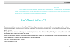
Fig.
Page J.8
5.
ú)
Explotlcd riew of tlte fr'ont suspen;iort assetn\l.t,
L_______ __-
FRONT SUSPENSION
l, Upper wishbone assembly (Rrght-hand)
2. Upper wishbone (Right-hand)
3. Upper wishbone ball pin
4. Ball pin socket
5. Spring
6. Top cover
7. Circlip
8. Grezr-se nipple
9. Rubber gaiter
10.
I
l.
Clip
Upper wishbone fufcrum shaft
Pinch bolt
Distance washer
12.
13.
14. Rubber bush (Upper wishbone)
15. Special wusher
16. Lorver wishbone assembly (Right-hand)
17, Lower wishbone lever (Right-hand front)
18. Lower wlshbone lever (RighËhand rear)
I9.
'Bolt
20. Sleeve
21. Washer
22. Lower wishbone fulcrum shaft
21. Distance washer
24. Rubber bush (lower wishbone)
25. Special washer
26. Shock absorber (front)
27. Shock absorber (bottoÍr bush)
28. Lower wishbone ball pin
29. Ball pin spigor
30. Morganite socket
31, Shims
32. T,ower ball pin cap
33. Tab washers
34, Grease nipple
35. Rubber gaiter
36. Gaiter retainer
37. Clip
j8.
Stub'axle carrier
39. Stub axle
40. Oil seal
41. Inner bearing
+2. Outer bearing
43. Front hub (Right-hand)
44. "D" washer
45. CreaSe nipple
46, Hub cap
47. Brake disc
48. Steering arm
49. Anti-roll bar
50. Rubber bush
51. Bracket
52. Distance piece
53. Anti-roll ba¡ Iink
54. Rubbe¡ busb
55- To¡sion bar
56. Bracket-torsion bar (rear end)
1
í
1
J
Page J.9
FRONT SUSPENS¡ON
IMPORTÄNT
Renerving the Rubber/Steel Bushes
It
ìs essential that the top wishbone ball pin is not
allowed to come into hard contact with the sides of the
ball socket. When testing the movement of the ball
in its socket, nrove the ball only in the direction of the
elongation.
lf the top wishbone is ¡emoved complete with the
stub axle carrier the assembly must not be held by the
top wishbone and the axle carrier allowed to swing on
the ball pin.
Rernoval of the Fulcrum Shaft
Release the two clamp screws locking v¡ishbone to
lulcrum shaft. Turn sliaft in a clockwise directìon,
looking from the rear, until the threaded portion of
the shaft is clear of the wishbone. Withdraw the shaft
through the wishbone arms.
Adjustment of the Ball Joint
The correct clearance of the ball pin in its socket is
'004'('10 mm.).
Shims for the adjustment of the ball joint are now
available
in
'004" ('10 mrn.) thicknesses.
To adjust the ball pin clearance to the correct figure,
Fig. 4, remove the circlip (1), cover plate (2) and spring
(4) from the ball
joint.
Clean thoroughly
all
the
component parts.
Fit shims (3) between cover plate (2) and upper ball
socket (5) until the ball is tight in its sockets when the
cover plate and circlip are refitted without the spring.
Remove shims to the value of '004'('10 mm.) and
re-assemble ball joint complete with the spring, when
it should be possible to move the ball pin by hand.
Finally lubricate with the recommended lubricant.
Note: Shims should not be added to ta,ke up excessive
wear in the ball pin and sockets; if these parts are badly
worn replacenrents must be fitted.
Drift or press out the bush from the bracket. Press
the ner.v bush into the bracl.:et ensuring that the bush
pro.jects lrom each side ol the bracket by an equal
amount. Fitting of the bush uill be facilitated if a
lubricant rnade up ol twelve parts of water to one
part of liquid soap is used.
LOWER WISHBONE
Removal
Slacken off but do not remove the hub caps from the
road u,heels; the hub caps are marked "RIGHT (OFF)
SIDE" and "LEFT (NEAR) SIDE" and the direction
of rotation to ren.ìove, that is, clockwise for tlie right
hand and anti-clockwise lor the left hand side. Make
up a block of hard wood to fit into the frame lower
cross tube section as shown in Fig. 7.
Remove the cable harness band clips from the cross
tube and insert the block of wood under the cross
tube; place thejack under the wooden block and raise
the car until the road wheels are clear of the ground.
Place stands under the blocks at the two outer ends
of the cross tube adjacent to the lower wisl-tbone ful-
crum pivots. Complete the renroval of the road wheels.
Do NOT place the jack or stands under the frame
cross tube without the wooden block inserted.
Disconnect the hydraulic brake pipe from the frarne
connection, remove tl.re brake pipe carrier brackets and
blank offthe connector to prevent ingress ofclirt or loss
of fluid.
Remove the split pin and nut from the steering tie
rod ball joint and drift out the tie rod enci from its
tapered seating ín the steering arm by tapping on the
side face of the steering arm adjacent to the balt pin.
Disconnect the upper rvishbone ball j oint as described
on page J.1 . If it is not required to remove the upper
wishbone completely for servicing raise the wishbone
to its full extent and tie to the frame.
Disconnect the lorver wishbone ball joint by remov-
ing the selllocking nut and drifting out the baìl pin
from ,its tapered seating in the lorver wishbone.
Remove the axle carrier complete with the b¡ake
caliper and disc. Place the jack under the lower suspension arm and raise the jack to take up the weight
of the car.
Fig,
6.
Section through one
bushed mo
Page J.10
of the upper
u
nt i ng brack e
wishbone rubberfsleel
ts.
Note: Do not lift the car off the stands.
Remove the self locking nut retaining the anti-roll
bar to the lower suspension arm.
FRONT SUSPENSION
Remove the split ltin and nuts retaining the telescopic
damper to the frame and the wishbone, e.xtract the
upper mounting bolt and withdraw the danrper.
Lou,er and remove the jack. IJnscrerv the two l¡olts
and loc]< u,ashers securing the torsion bar rear adjuster
lever to the franle and slide tlre lever fon¡,ard until it is
clear of tlle torsion bar splines.
Renrove the locking bolt from the torsion bar frol.rt
must not be tightened until the complete front
sus-
pension assembly has been fitted and the full weight of
the cal is on the suspension. Omitting to carry out
thìs procedure will result in undue torsional loading
of the rubber busl.res with possible premature failure.
It will be necessary to re-bleed the front hydraulic
brakes after refitting the lower wishbone assembly as
described in Section L "Brakes".
Renewing the Rubber/Steel Bushes
Drift or press out the bush from the bracket. Press
the new bush into tl-re bracket so that the bush projects
from each side ol the bracket by an equal amount.
Fitting of the bush will be facilitated if a lubricant
made Lrp of twelve parts of water to one of liquid soap
is used.
"i:
i::,
mounting. Slide the torsion bar rearwarcls until the
front splines are clear ol the wishbonc and withdraw,
in a lorward direction.
Remove the two bolts and washers retaining the
fulcrum shaft ¡ear carrier to the chassis frame.
Remove the four bolts, nuts ancl ivashers retaining
the fulcrum shalt front carrier bracket to the chassis
frame. Extract the split pin and remove the nuts frorn
the lower wishbone shaft. Withdraw the brackets and
Fig.
8.
ol the lower tvishbone rubberfsteel
bttshed ntount ing bracket.s.
Section through one
¡ubber bushes.
Refitting
Refitting of the lower wishbone assembly is the
reverse of the removal procedure, but it will be neces_
sary to ¡eset the torsion bar as described under
"Torsion Bar-Adjustment" page J. 15. Check the
lower wishbone ball joint for clearance as described
under "Lower Wishbone Ball Joint".
Examine the ball joint rubber gaiter. Replace if
wom or damaged.
The slotted nuts at each side of the fulcrum shaft
LOWER \ryISHBONE BALL JOINT
Dismantling
Release the wire clip (4, Fig.
rubber gaiter (3).
9) and remove
the
Tap back the tab washers (11) and unscrew the four
setsc¡ews (12) securing the ball pin cap (9) to the stub
axle ca¡¡ier.
Remove the cap (9), shims (8), ball pin socket (7),
and ball pin (6).
Page J.l I
FRONT SUSPENSION
Re-assembling
Re-assembling
is the reverse of the
disnrantling
proceclure but, il necessary, re-shim the ball joint to
obtain the correct clearance ol '004" to '006'('10 mm.
to '15 mm.).
Note: Shims should not be removed to take up
excessive wear in the ball pin and sockets; if
these parts are badly worn, replacements
should be fitted.
)
Adjustment of the Ball Joint
The correct clearance ol the ball pin in its socket is
I 5 m m.). Shims for adj ustment
ol the ball joint are available in '002" ('05 mnt.) and
'004" to'006' (' lOmrn. to'
'004' ('10 mm.) thicknesses. To adjust the ball pin
clearance to the correct figure, remove the shims one
by one until, with the ball cap lully tightened, the ball
is tight in its sockets. Fit shims to the value of '004"to
'006'('10 mm. to'15 mm.) which should enable the
shank ol the ball pin to be moved by hand.
STUB AXLE CARRIER
Removal
Jack up the car and remove the road rvheels as
described unde¡ " U pper Wishborle-Removal"
Page 1.7.
Disconnect the hydraulic blake pipe from the fralne
connection, remove the brake pipe carrier and blank
off the connector to prevent ingress of dirt and loss ol
fluid.
Remove the self-locking
Fig.
I
)
9.
The lcwer wishbone ball joint.
Nut
Washer
4
Rubber gaiter
Circlip
5
ó
Ball pin
3
Spigot
7. Socket
8. Shims
9. Ball pin cap
t0. Greasè nipple
I 1. Tab u,ashers
12.
Setscreu,s
nut and plain washer
securing the upper wishbone ball joint to the stub axle
carrier. Drift out the ball from its tapered seating, by
tapping on the side face of the ca¡rier adjacent to the
pin.
Raise the wishbone to its
frame.
full extent and tie back to
Remove the split pin and nut from the steering tie
rod ball joint and drift out the tie rod end from its
tapered seating by tapping on the side face of the carrier
adjacent to the pin.
Remove
the selflocking nut and plain
securing the lower wishbone ball
Page
J.l2
washer
joint to the stub axle
FRONT SUSPENSION
carrier. Drift out the ball pin from its tapered seating
by tapping on the side face of the lower wishbone
washer (3) from the end of the stub axle shaft. The
hub can now be withdrawn by hand.
adjacent to the ball pin.
Remove the axle carrier.
Dismantling
Refitting
Extract the oil seal (8). Withdraw the inner races of
the taper roller bearings (7). Examine bearing for
wear. If new bearings are to be fitted the outer races
can be drifted out from the hub.
Refitting is the reverse of the removal procedure.
It will be necessary to bleed the front hydraulic brakes
system after reûtting the axle carrier and suspension
arms as described in Section
L "Brakes".
WHEEL HUBS
Refitting
Removal
Refitting is 'the reverse of the removal procedure
but it will be necessary to re-lubricate the bearings as
detaìled in "Routine Maintenance" at the beginning of
Jack up the car and remove the road wheel. Discon-
nect the flexible hydraulic brake pipe from the frame
connection and blank off the connector to prevent the
ingress of dirt and loss of fluid.
Remove the locking wire from the
two
this section and adjust the end ffoat ofthe hub bearings
as described in the following paragraph.
When refitting the brake caliper care should be
taken to ensure that the correct clearances are maintained between'the inner faces of tho caliper and each
face of the brake disc. For method of checking the
clearance and tolerance permissible refer to Section
L "Brakes". Re-bleed the hydraulic brakes after
refitting as described in Section L "Brakes".
brake
caliper mounting bolts and unscrew the bolts noting
the shims fitted between the caliper and the mounting
plate. Remove the caliper. Remove the split pin,
(2,Fi9.10), retaining the hub nut; holes are provided
in the side of the hub through which the split pin can
be withdrawn. Remove the slotted nut (l) and plain
lt¡rã-l
Fig,
Nut
Split pin
"D"
washer
4.
Outer bearing
5.
Wheel hub
Brake disc
6.
10.
The
front hub.
7. Inner bearing
8. Oil seal
9. Stub axle
10.
11.
12.
Stub axle securing nut
Brake disc securing bolt
Nut
Page J.13
FRONT SUSPENS¡ON
from the pressure chamber that may have accumulated
due to the damper having been stored in a horizontal
Bearing End-float Adjustment
The correct end float of the wheel bearings is '003"
to '005' ('07 mm. to '13 mm.). It is particularly
important that the end float does not exceed '005"
posltron.
Hold the danrper in its normal vertical position w'ith
the shroud uppermost and make several short strokes
(not exceeding more than half-way) until there is no
lost motion and finish by extending the damper to its
full extent once or twice. Do not extend the damper
fully until several short strokes have been made first.
After the operation ol "bleeding" the hydraulic dampers should be kept in their normal upright position
until they are fitted to the car.
('13 mm.) otherwise the brakes may tend to drag and
not function correctlY.
The wheel bearing end float can be measured with a
dial indicator gauge, mounted with the plunger against
the hub. If a gauge is not available proceed as follows:
Tighten the end nut until there is no end float, that
is, when rotation of the hub leels slightly "sticky".
Slacken back the hub nut between one and two flats
depending on the split pin hole relative to the slots in
the nut.
IMPORTÄNT
If
allow the suspension
HYDRÄULIC DÄMPERS
to be removed do not
unit to drop lower than the
the hydraulic danrper is
normal rebound position, otherwise the top ball joint
may "neck" in its housing.
The telescopic hydraulic dampers are of the sealed
type with no provision for adjustment or "toppingup" with fluid, therefore, in the event of a damper
being unserviceable a replacement damper must be
Support the outer end of the lower wishbone before
removing the damper.
firted.
Before fitting a damper to the car it is advisable to
carry out the following procedttre to "bleed" any air
Removal
Jack up the car under the lou'er wishbone at a point
adjacent to the damper lower mounting until the
wheels are clear of the ground.
Remove the road wheel.
Remove the split pin and nut from the damper top
and bottom mounting bolts.
Remove the top mounting bolt, withdraw the damper
from the bottom mounting and remove from the car'
=.
B$ttbe
Refitting is the reverse of the removal procedure,
tut the slotted nuts shouìd not be tightened until the
lull weight of the car is on the suspension. Omitting
to carry out this procedure will result in undue torsional loading of the rubber bushes with possible
f ry. I l.
Page
J.l4
The hyCraulic damper attaclmrcnt pointt.
ultimate failure.
FRONT SUSPENSION
ÄNTI.ROLL BAR
Removal
Remove the four bolts, nuts and washers from the
anti-roll bar support brackers (51, Fig.5) on the
chassis member. Withdraw the two distance pieces.
Remove the self-locking nuts and withdraw the two
bolts attaching the arm to the lower wishbone. To
separate the anti-roll bar (49) from the link arm (53),
remove the self-locking nuts and the washers and
withdraw the two
rubbers are split
the anti-roll bar.
to
bolts, The anti-roll bar bracket
enable them
to be removed from
Renewing the Link Ärm Bushes
Drift or
press out the bushes from the link arm upper
and lower eyes. Press the new bush into the eye
ensuring the bush projects from each side by an equal
amount. The fitting of the bush will be facilitated if a
lubricant made up of twelve parts of water to one part
of liquid soap is used.
Fig.
12.
Refitting is rhe reverse of the removal procedure.
It is most important when attaching the support
of checking the standing
height.
Roll car forward three lengths.
V/ith the torsion bar correctly adjusted the measurement
Reftting
Showing the method
A
shciuld be 8f
"-[{'
(22.2!.64
cm.).
Adjustment
lf
adjustment is necessary proceed as follows.
TORSION BAR-ADJUSTMENT
Jack up the car and place stands under the lower
wishbone fulcrum support bracket.
Note: DO NOT place jack or stand immediately
under the forward frame tubes.
Remove the road wheels.
Disconirect the upper wishbone ball joint from the
stub axle carrier, as described on page J.7.
Disconnect the steering tie-rod ball joint from the
stub axle carrier as described on page J.12.
Disconnect the anti-roll bar as described on page
Checking
J.r5.
bracket to the frame member and also when tightening
the self'-locking nuts on the link arm attachment bolts
to have the full weight of the car on the suspension.
Omitting to carry out this procedure will result in
undue torsional loading of the rubber bushes with
possible premature failure.
Check that the car is full of petrol, oil and water.
If not additional weight must be added to compensate
for, sav, a low level of petrol (the weight of I0 gallons
of petrol is'approximately 80 lbs. (36.0 kg.)). Before
any check on torsion bar setting is made the car must
be placed on a perlectìy level surface, wheels in the
straight ahead position and tyre pressures correctly
adjusted to:
Front 23 lbs. per sq. in. (l .62 kg.lcm.z)
Rear 25 lbs. per sq. in. (1 '76 kg.lcrn.t)
Place the jack under the lower wishbone at a point
to thç damper lower mounting. Raise jack
adjacent
but do not ]ift the car offthe stdnds.
Remove the split pins and slacken the nuts retaining
the lower wishbone rubber mountings.
Remove the hydraulic damper as described on page
J. 14, Lower the .¡ack.
Remove the two bolts and nuts securing the torsion
bar ¡ear adjuster lever to the frame. Fit setting gauge,
with two holes drilled at I7l{" (45'24 cm.) cenrres ro
damper mounting points to position lower wishbone.
Page J.15
FRONT SUSPENSION
Note: The setting gauge can be easily made using
Turn in direction required and engage fresh splines.
Fig. 13 as a reference.
The two holes in the torsion bar rear adjuster lever
and the corresponding holes in the frame should now
be in line. If holes are not in line adjustment must be
If position of lever is now correct refit rear bolts and
nuts, also front locking bolt and nut and fully tighten.
made as follows:
(Ð
Note which way lever requires to be rotated to
bring holes in line, Mark position of the lever on
shaft, remove by sliding off the splines, turn in
direction required, and locate on fresh splines.
Check lever position.
(ii)
Repeat ope'ation
Remove the setting gauge and locate damper on
lower mounting.
Raise jack
until damper upper retaining bolt will
eye. Reflt nuts but
do not tighten. Reflt top wishbone steering tie-rod
pass through bracket and damper
and anti-roll bar.
Repeat operation to left hand side.
if further adjustment is neces-
sary. It should be noted that the rear end of the
torsion bar has 25 splines whereas the front end
has only 24 splines. This pèrmits the bar to be
used as its own vernier and allows for a very fine
adjustment. If this very fine adjustm'ent is necessary slide torsion bar out of front splines after
first removing tlie locking bolt.
Refit road wheels, jack up car, remove stands and
lower car.
Tighten damper securing nuts and insert split pins.
Tighten lower wishbone fulcrum shaft nuts and insert
split pins. Tighten nuts securing anti-roll bar.
Roll car forward three lengths and re-check standing
height of car which should now be as shown in Fig. 12.
l'(s-r uu)
i'/
2 (12.
17fi(, r,nc") lSjiä,
Fis. 13,
Page J.16
The lorsion bar setting gauge.
r,c")
FRONT SUSPENS!ON
CÄSTOR ANGLE-,ADJUSTMENT
Check that the car is full of petrol, oil and water.
If not, additional
weight must be added to compensate
for, say, a low level ofpetrol (the weight of l0 gallons
of petrol is approximately 80lbs. (36.0 kg.)). Ensure
that the tyre pressures are correct and that the car is
standing on a level surface.
Usiag an approved gauge check the castor angle.
Castor angle 0"_þ
|'
positive
Note: The castor angle for
by more than f".
each wheel must not vary
Adjustment is effected by rotating the round threaded
shaft on the front suspension upper wishbone bracket.
Remove the split pins and release the úuts situated
at the rear and front of the fulcrum shaft and release
the wishbone clamping bolts. The shaft may now be
turned with a spanner placed on the two flats-provided
on the shaft.
Fig.
14.
Note: It is essential that the split pins be removed
and the nuts released from the shaft otherwise a strain will be placed on the rubber
mounting bushes.
To increase positive. castor angle rotate the shaft
anticlockwise (viewed from the front of the car).
To decrease positive castor angle rotate the shaft
clockwise, After adjustment retighten the clamp
bolts.
The slotted nuts situated at the front and rear of the
fulcrum shaft should not be tightened until the full
weight of the car is on the suspension. Omitting to
carry out this procedure will result in undue torsional
loading of the rubber bushes with possible ultimate
failure. Refit split pins,
The front of the car should be jacked up when
turning the wheels from lock to lock during checking.
If any adjustment is made to the castor angle, the
front wheel alignment should be checked and if necessary reset as described
in
Section
I
"Steering".
The castor angle is adjusted by rotating the shalt
indicated by the arrow.
Page J.l7
FRONT SUSPENSION
CAMBER ANGLE-ÄDJUSTMENT
Check that the car is full ol petrol, oil and water.
If not additional weight must be added to compensate
for, say, a low level of petrol (the weight of l0 gallons
of petrol is approximately 80 lbs. (36'0 kg.)).
Ensure that the tyre pressures are correct and that
the car is standing ou a level surface. Camber
Angte {"}}o positive. The camber for each wheel
must not vary by more than {".
Line up the front wheel being checked parallel to the
centre line of the car.
Using an approved gauge check the camber angle.
Rotate the wheel being checked through 180" and
The top holes in both front aud rear shtms are
slotted and the bolts need only be slackened off to
remove or add shims, The bottom holes are not
slotted and it is necessary to remove bracket fixing
bolts completely.
Inserting shims increases positive camber angle;
removing shims increases negative camber angle or
decreases positìr,e camber angle. Remove or add an
equal thickness of silims from each position otherwise
the castor angle will be affected.
It should be noted the lu-' (1 '6 mm.) of shimming
will alter the camber by approximately {'.
front wheel in a similar manner.
any adjustment is made to the camber angle the
lront wheel alignrnent should be checked and if necesCheck the other
re-check.
Adjustment is effected by removing or adding shims
to the front suspension top wishbone bracket at iwo
points, namely, the front and rear of the bracket.
If
sary be re-set as described
The camber angle is adiusted by m9ary of shims indiRemove or add an equa! tltickness of shims
cøed by llrc arrows,
'
Fig. 15.
Jrom each position.
Page J.18
in Section I "Steering".
FRONT SUSPENSION
ACCIDENTAL DAM.ÀGE
The following dimensional drawings are provided
to assist in assessing accidental danrage. A component
I IN 8
suspected of being damaged should be removed from
the car, cleaned oflì the dimensions checked and compared with those given in the appropriate illustration.
TOTAL TAPER
(13
['ig. 16.
O
cm
)-
The stttb axle carrier.
Page J.19
FRONT SUSPENSION
(z¿.¿ cu)
3.
8A
(2o'¡l
'
3'
cM)
I
I
Fis. 18.
tôZ
Fis. 17,
lever-rear
The Ltpper wishbone,
Fig. 19.
Page J.2O
The lower wishbone
The lower wishbone
lever-[ronl.
Printed in England by Buckler & r¡r'ebb Ltd., Church Strcet, Birmingham
3
SECTION K
REAR SUSPENSION
3.8 $E)) TYPE
GRAND TOURING MODELS
INDEX
Page
K.3
K.4
K.4
Routine Maintenance
Recommended lubricants
K.4
Rear Suspension
Removal
K.5
Refitting
K.5
Road Spring and Hydraulic Damper Assemblv
K.6
Removal
K.6
Hydraulic Dampers
Removal
K.7
Refitting
K.7
Radius Ann
Removal
K.1
Refitting
K.7
Wishbone
Removal
K.l0
Refitting
K.ll
Wishbone Outer Pivot
Removal
Dismantling
Re-assembly
Bearing adjustment . .
Refitting
K.t2
K.t2
K.l2
K.l3
K,l4
Wishbone Mounting Bracket
K.14
K,t4
Rear Wheel Camber-Adjustment
Page K.2
K.15
REAR SUSPENSION
Description
The rear wheels are located in a transverse plane by two tubular links of which the top link is the half shafts
universally j.ointed at each end. The lower link is pivoted at the wheel carrier and at the crossbeam adjacent to
the differential casing. To provide maximum rigidity in a longitudinal plane the pivot bearings at both ends of the
lower link are widely spaced. The suspension medium is provided by four coil springs enclosing telescopic hydraulic
dampers, two being mounted on either side of the differential casing. The complete assembly is carried in a fabricated steel crossbeam. The crossbeam is attached to the body by four "Vee" rubber blocks and is located by
radius arms. The radius arr]1 pivots are rubber bushes mounted on each side of the car between the lower link and
a mounting point on the body structure.
An anti-roll bar fitted between the two lower wishbones, is attached to the underlrame side members by rubber
insulated brackets.
Fig. 1, Sectioned view of rear suspensiotr
Page K.3
REAR SUSPENSION
DATA
Later Cars
Early Cars
Rear Road Spring
Free length (approx.)
Number of coils (approx.)
Wire diameter
Identification colour
l0'l'
I0'5"
(25 '65 cm.)
(26 '67 cm.)
l0
eå
'432' (l
l'0
mm.)
Red
Telescopic
Dampers
Road V/heel Movement from mid laden position
Full bump ..
Full rebound
3å"
3å',
50+"
Track
1".r,.à' negarive
Rear Wheel Camber
Churchill Tool No.
Special toois
J.l r
J.l4
Rear rcad spring removal tool
Dummy shaft for wishbone fulcrum points (2 olI¡
ROUT¡NE MAINTENANCE
EVERY 5,000 MILES (8,ooOKM.)
Wishbones
Lubricate the wishbone lever pivots. Three grease
nipples are provided on each wishbone, see Fig. 2.
irz-eel
FÌg.
2.
Outer antl inner pirot
beat ing graa.re ttipples
Recommended Lubr¡cants
Castrol
B.P.
Shell
Duckham
I
Regent
Caltex/Texaco
Wishbone
Pivots
Mobilgrease
Castrolease
Retinax
MP
LM
A
t
Page K.4
E
nergrease
L2
LB
l0 I
Marfak
All
pLrrpose
REAR SUSPENSION
REAR SUSPENSION
Removal
Slacken the two clamp bolts u,hich secure the tail
pipes to the silencers.
Rernove the tu'o nLlts, bolts ¿rnd washers securing
the exhaust tail pipes to the centre mounting point
under the rear ol the bocly.
Withdraw the exhaust tail pipes.
Detach the radius arms at the front end.
Place
a stout piece of wood approximately
9"
I" (22'8 cm. . 22'8 cn't.x25.4 mm.) between the
rear suspension tie plate and the jack.
Jack up the rear of the car and place two chassis
stands of equal height under the body forward ol the
radius arm mounting posts. Place blocks of wood
between the chassis stands and the body to avoid
9" >
Remove the spÌit pin, washer and clevis pin securing
the handbrake cable to the handbrake caliper actuating
levers mounted on the snspension cross beam.
Slacken the locknut and screw the outer handbrake
cable screw out of the adjuster block.
Remove the four bolts and self locking nuts securing
the mounting rubbers at the front of the cross beam to
the body frame. Note carefully the number and
location of the packing shims between the mounting
rubbers and body frame. Remove the six self locking
nuts and four bolts securing the rear mounting rubbers
to the cross beam.
Remove the lour self locking nuts and bolts securing
the propeller shaft to the differential pinion flange.
Lower the rear suspension unit on the jack and
withdraw the unit from under the car as shown in
Fig.
3.
damage.
Renrove the rear road wheels.
Leaving the jack in position under the differential
tie plate remove the two sell locking nuts and bolts
securing the anti-roll bar links to the roll bar.
Disconnect the flexible brake pipe at the connection
on the body.
I
Refitting
Refitting is the reverse of the removal procedure.
all mounting rubbers for deterioration.
Bleed the braking system as described in Section L.
Check
" Brakes".
If the radius arms have been removed the rear
¡r -¡ l(tn:¡¡tul ol Iht'tt,ttt su\lt('n\ittl ,,,. tttl¡l !¡'¡nt Iltt ttn
l)¿Lec
K.5
REAR SUSPENSION
suspension should be at the normal riding height
before tightening the radius artn securing nuts on the
rear suspension r¡'ishbone. Refit the radius arnls as
described on page K.7.
If the rear suspension mounting rttbbers have been
removed it is essential that the rubbers are refitted with
the cut-away flange towards the suspension unit as
shown in Fig 4.
frert]
Fig 5 H t tlt uttlìt letitp(r Itrututl¡tt.t! lro¡tIl\
each hydraulic danrper to the cr-oss beam.
Withdraw the lryclraulic datuper antl road spring
Fig.
4.
Sho*,ing the correcl position of the reot
suspensiott mounling rubber
assembly.
Refitting
Refitting is the revelse
ol the removal procedure.
IMPORTANT
The following removal and refitting operations are
described assuming the rear suspension is removed
from the car. lf it is possible for the operations to be
carried out with the rear suspension in position
on the car the fact will be noted in the text.
ROAD SPRING AND HYDRAULIC
DAMPER
,ASSEMBLY
Removal
The road spring and hydraulic damper assembly nray
be removed from the car with the rear suspension
assembly in position.
Remove the two self locking nuts and washers
securing the two hydraulic dampers to the wishbone.
Support the appropriate i¡,ishbone and drift out
the hydraulic damper mounting pin, Fig. 6.
Remove the self locking nut and bolt securing
Page K.6
Fig.6
Drifting out thc hrd¡aulic ilanrper nrcunting pÌn
REAR SUSPENSION
HYDRAULIC DAMPERS
The telescopic hydraulic dampers are of the sealed
type with no provision for adjustment or ..topping_up,,
with fluid. Therefore, in the event of à Ou.fe,
becoming unserviceable a replacement must be fitted.
Before fitting a damper to a car it is advisable to
carry out the following procedure to .,bleed,' any air
from the pressure chamber that may have accumulated
due to the damper having been stored in the horizontal
position. Hold the damper in jrs normal vertical
position with the shroud uppermost and make several
short strokes (not extending more than half way)
until there is no lost motion. Finish by extending the
damper to its full length once or twice. Do not extend
the damper fully until several short strokes have beelr
made first. After the operation ol .,bleeding,,, the
hydraulic dampers should be kept in their normal
upright position until they are fitted to the car.
Refitting
Compress the roacl spring, uiilizing Churchill tool
J. 11 and SL. 14, sufficiently to allow the hydraulic
damper to be passed through the
ring
No.
pad and the split collet placed
7. Ensure that the split colle
seating
correctly.
Release
Fig.
aÍe
the
oad
sprlng.
On early cars fit the machined recessed aluminium
pad to the shrouded end of the damper. Compress the
road spring and pass the damper through the spring
and fit the other aluminium pad and secure wjth the
split collet, Release the pressure on the road spring.
Refit the road spring and hydraulic damper assembly
as described on page K.6.
RADIUS ARM
Removal
Remove the road spring and hydraulic damper as
described on page K.6.
Utilizing a suitable press, Fig. 7, compress the road
Removal
Remove the locking wire from the radius arm safety
strap and securing bolt.
Unscrew the
two self locking nuts sectrring the
safety strap to the body floor.
P-emove the radius arm securing
bolt and spring
washer and remove the safety strap.
Withdraw the radius Ârm from the mounting post
on the body.
Remove the self locking nut and bolt securing the
anti-roll bar to the radius arm..
Remove one of the self locking nuts securìng the
hub bearing assembly fulcrum shaft to the wishbone.
Drift out the fulcrum shaft from the wishbone and
hub assembly as described on page K,12.
Re¡not,e the self locking nut and bolt securing the
radius arm to the wishbone and remove the radius arm.
Examine
the radius arm mounting rubbers for
deterioration.
Fig.
7
Rettnring /lrc rear rood spring .[t.ont the hlulraulic lctttrper
x.ith Chttrchill tool J.il in coìi¡utoiort nnlt i[.t¿
spring until the split collet can be removed from under
the road spring retainin_e pad,
Carefully release tire pr-essure ou the road spring
and u'ithdra* thc hvdraulic damper.
Orr early cars an alurninium pad was fitted to either
end of the spring. The pad fitted to the sh¡ouded end
of the damper was recessed to receive the shroud.
Refitting
Refitting is the reverse of the ¡emoval procedure.
When replacing the large radiirs arm body mounting
rubber, the two holes should be in the longitudinal
positlon in the radius arm as shown in Fig. 9.
The rubbers on the wishbone mounted end of the
radius arm can be pressed out. Ensure that the
rubbers are refitted with an equal amount of space
showing on each side of the radius arm.
When refitting the hub bearing assembly shaft
reler to page K.14.
Page K.7
REAR SUSPENSION
a
!'
ss
,¡
¡
L¡*
Page K.8
REAR SUSPENSION
l. Reur suspension cross member,
2. Rubber mounting.
l. lnner fulcrurn mounling bracket.
4. Shinrs.
5. Tie platc
6. Wishbonc.
7. lnrrcr lulcrLrnr shaft.
8. Dist¿rncc tubc.
9. Bcitr¡ng (uhe.
I0. Nee dle hcarirrgs.
I l. Spacing colllr.
t'2. lnner thrusl washel'.
ll. Sclling rirrg.
l.t. Scaling r-irrg retainer.
15. ()utcr tlìnlst w¿ìsher.
16. Gr-cusc rripplc
17. ()t¡tcr lulcrum shalt.
18. Distirnce tubc.
I 9. Shinrs.
20. Bcarirrg.
2l . (-til scnl lr¿rck.
?2. Oil se¡1.
21. Shims.
21. SelI locking nu(.
25. Hub carrier.
26. (ìrearc nipple.
27. Glease retainirrg czrp.
28- Rear hub.
29. Hub cap.
30. Oii seal.
31. Oil seal track.
32. Or¡ter betrirrg.
3-1. Sptcer.
34. Shims (early crrrs only).
35. Oil seal track.
16. Half sh¡ft.
37. Flangc yoke
18, Splined yoke.
3.9. Journul assenrbl¡,.
40. Shim.
. Coil spring.
42. Shocklubsorber.
43. Se¿rt. '
44. Retlining collet.
45. Anli-roll bar.
46. Rubber bush.
47. Br¿rckòt.
4l
-18. Link.
4q.
50.
51.
Rubber bush.
Bump slop.
Radius arnr
REAR SUSPENSIO N
Fig 9
t in tltt'
Shox'irtg tlte positiotr of fhe tttortttrirtg t ttbhct
t
Refit the safety strap into position, refit the spring
washer and radius arm securing bolt.
Rellt the two bolts and nuts securing the salety strap
to the body.
Tighten the radius arm securing bolt to 46 lb.ft.
(6'36 kgm.) and pass the locking wire through the hole
in tÌre head olthe bolt and secure round the salety strap.
atlius arut
Remove the six self locking nLrts and bolts secLrring
the tie plate to the cross bearl.
Renrove the eight selllocking nuts and bolts securing
the tie plate to the inner firlcrurl rvishbone nrounting
brackets and lenrove the tie plate.
Rerrove one olthe sell lockirrg nuts securìng the hub
\ryISHBONE
Removal
Remove the hydraulic dampers frorn the appropriate
wishbone as described on page K.6.
Fig ll
tht t'i,sltt lxtlt¡ tltìrlt v,r'tttt' tlta
rrtttt't lhlct trttt ntotttuitt¡¿ ht ut l,¿t
Slttttirt,g
bearing assenrbly fulcrunr
drilt out the fulcrunl shalt.
Separate the hLrb carrier
shims are fitted betu'een the
Fis. 10. Shovittg tlrc sit bolts thiclt secute thc rie plute to
cross beant
Page K.10
thc
shalt to the wishbone and
see
Fig
16.
frorn thc ri'ishbone. ll- any
u,ishbone and hub assernbly
noie the alìrount cnd position of the shinrs as it is
essential to replace the exact anlount in the correct
REAR SUSPENSION
Fis l-1. SltorÌtrg tlte wishbotrc
irnter litt
k unrl contponerls
larger lork of the wishbone lever press one roller cage
into position, with the engraving on the roller
cage
facing outwards.
Insert the roller spacing tube ancl press in the other
roller
Li,t1.
12. Sho*'ing tltc dutnn¡ slnl't in ytsitiott in tht,hub ccurier
position. To facilitate refitting siide a dumn.ìy fulcrurn
slraft ChLrrchill tool No. J l4 through the hLrb carrier.
Place a piece o[ sticky tape over each of the hub
carricr assenrbly oil seal tracks to prevent theln
cage.
Repeat lor the other side
Insert the bearing tubes. SnrQar the for¡r outer
thrust washers, inner thrust r.'r,ashers, oil sea'ls and oil
seal retainers rvith grease ancl place into position on
the il,ishbone, see Fig.
13.
beconring displaced
Retnove the self locking nut securing the radius arm
to the wishbone. Withdraw the special thin headed
bolt and rentove tlre radius arm front tbe u,ishbone.
Remove the self locking nut securing the wishbone
fulcrunr shalt to the cross beanr.
Drift the inner lulcrunt shaft out ol the
rvishbone
and inner fulcrunl moLrnting bracket.
Withdrail, the wishbone assembly and collect tite
lour outel'thrLlst u,ashers. inner thrust
seals and oil seal retainers.
Exanline the oil seals lor deterioration.
rvashcl.s, oil
Remove the two bearing tubes.
There is no need to reutove the spacer fitted betr.l,een
the inner fulcrum mounting bracket unless the ntounting bracket is to be replaced. To remove the spacer,
tap oLìt of position. To remove the needle rollers
gently tap the needle cages out ol the u,ishbone using
a suitable drilt. Renrove the neecjle roller spacer.
Refitting
If the needle rollers have beelt removed lrom the
Fi¡7.
l1 Tuppittg tht, tlttntntt s/trtfir inro p()\¡tit)n ttt tl¡a
v.i.çhbone
ittttt'r lirlct ttnt
Offer rrp the'"r ishbortr: to thc illlre'r l-l.rlcrum rnoLrntirrg
bracket with the rutlius anlr llloLtntinq bracket to',i,ards
the front ol tlte clr Aiiun the llolcs ancl :!pacers.
Press a dulnnr,r shllt Chrr¡'uhill tool Ntr J.l4 throush
each side ol the cross bc-anr lrlrd u ishhtrne_
Puqe K.1l
REAR SUSPENSION
The dunrmy shafts locate the ivishbone. thrust
and inner fulcrunl rttoLtttting
bracket and facilitate refitting ol the fulcrurl shalt.
washers, cross beanr
Renrove the t'"r o pieces ol sticky' tn¡re holding the
oil seal tracks in position.
Ofler up the u ishbone to the hub assertrbly'.
Using a durtrnty shaft. Churchill tool No. J.14,
line up tlre u'ishbone hLrb assentblv oil sell tracks and
spxcers. Snreal tlre f'ulcrutl shal't r¡'ith grease attd
gently tap thc ftrlcluir shalt into position and clisplace
the dumnlv shal't.
It r.i'ill be lorrud adv'arrtlgeous to apply a snrall
of pressure on the locating bar ägainst the
anrount
fulcrunr shaft to preve¡ìt the bar beirrg knocked out of
posiLiorr ancl allou ing a spaccr to be cìis¡rlaced. ll a
spacer is clis¡rlircccl it nray be necessary to repeat tlre
o pe
rat lo n.
Sliclc thc ft¡lcrunr shaft thlough the w'ishboue atrd
hub carlicr Usirrg l'cclcr -qau-scs check the alloltnt of
clearance betrvecn the hub carrier and the wishbone
ll' ttcce ssary fìt suffìcient shirns
betrvecn the hLrb carrier and the u,ishbone to centralize
the hLrb calrier. Tighten the nuts on the lLrlcrurn shalt to
55 lb.it. (7'60 k-unr.).
lever. see Fig. 19.
Check the rear suspension ca¡lbcr angle as
cribed on page K.15.
Fig. t-5. Drifting tht'ittncr Jirlcruttt
^^ltu.lt
into potition untl div
placing thc dutnntr rlnlis
cles-
Refit the hydraLrlicdampersasdescribed on page K.7.
Refit the rear suspension as described on page K -5.
Re-l ubricate the wishbone fu lcru rr sha lts as descri bed
in "Routine Maintenance" at the beginning ol this
sectro
r'ì.
Snrear the lulcrunr shalt with grease and gently tap
the shaft through the crclss bearr. rvishbone and inner
fulcrum mounting bracket. As the fulcrurn shalt is
tapped into position the short dumnry shalts u,ill be
displaced from the opposite side. It will be found
advantageous to keep a slight arnoun[ ol pressure
exerted on the dummy shafts as they ernerge from the
cross bearrr. This wilt reduce tlre tendency for the
dummy shafts to be knocked out of position and allorv
a spacer or thrust washer to be displaced. lla rvasher
or spacer becomes displaced it will be necessary to
WISHBONE OUTER PIVOT
Removal
Support the hub carrier and wishbone.
Ren.love one of the sell locking nuts securing the
outer hrlcrunl sliaft.
Drift out the fulcrunr sbalt. Fig.
16. and collect the
shinrs, ilany, between the hub carrier and the rvishbone.
Separate the hub carrier and u,ishbolre.
remove the fulcrum shaft, dumrny shalts and r¡,ishbone
and then repeat the operation.
When the fulcrunr shaft is in position tiehten the
trvo self locking nuts to 55 lb.it. (7 60 kgm.) with a
torque u'rench.
Refit the eight bolts and sell locking rruts securing
the tie plate to the inner lulcrunr wishbone nroLrnting
bracket.
Refit thc six boits ar.rd sell locking nuts seculing the
tie plate to the cross bear¡.
Refìt the radius arm to the *ishbone as described
on page K,7.
Page
K.l2
Dismantlíng
Renrove the oil seal track and prise out the oil seals
Remove the inner races of the tapered roller bcarings.
spacers and shims.
Re-assembl¡'
Refit the inuer races lor the tapered roller beerings
Fit the spacers ¿tnd a knort,n quantitv of shinls- thi
REAR SUSPENSION
Bearing adjustment is effected by shims fitted between
the two fulcrum shalt spacer tubes. The correct
bearing adjustment is 000'- 002" ( 00 rnrr.05 mm.) pre-load.
Shims are available in sizes
of .004" ('l0l mrr.) and
'007' ( i7 mm.) thick and i+" (2S.67 rnrn.) diameter.
Fig.
l6
Dri/ring out thc x¡:hboilc outer fiicrunt
shaJr
is necessary to obtain the correct bearing adjustment
as described in the following paragraphs.
Fit the tapered roller bearings and oil seal tracks.
Bearing Adjustment
Il it is necessary to adjust the tapered roller bearings
it will be necessary to extract the hub from the rear
axle half shaft as described in Section H "Rear Axle"
A simple jig should be made consisting of a piece of
platesteelapproximatelyT",,. 4" r ¿" (17'7cm..< 10. lcm.
;<9'5mrn.). Dritl ancl tap a hole sLritable to receive the
outer fulcrum shaft. Place the steel plate in a vice and
screw the fulcrum shaft into the plate and slide an oil
seal track onto the shaft. Place the assemblv into
position on the fulcrum shaft minus the oil seals and
wjth an excess of shims, of a known quantity, between
the spacers. Place an inner wishbone fork or¡ter thrust
rvasher onto the fulcrum shaft so that it abuts the oil
seal track. Fill the renraining space on the shaft with
washers and secure with a nut. Tighten the nut to
55 lb.lt. (7'60 kgm), Press the hub carrier assembly
towards the steel plate using a slight trvisting motion
to settle the rollers onto the bearing surface. Maintain
a steady pressure against the hub carrier and using a
feeler gauge measure the arnount olclearance between
the large diameter washer and the machined face ol
the hub carrier.
Fig. 18. lvleaturirtg tltc antottttt of cltø once L¡elvectt the hub
cartier arul large tu.rhcr to d¿ttttninc the end float in Íha bcarings
Pull the hub carrier asset.nbly tou'alds tlie lar_ge
to settle
the rollers onto the bearing surlace. lvfaintain a
steady pressure against the hub carrier and using
leeler gauges measure the alrount of clearance betrveen
the lnrge diameter il'asher and the nrachirled face of
diameter wasìrer sìi_uhtly rot¿tting the carrier
|?4ól
Fig l7
Settiott thtorrglt htth carricr untl tislthont, shottirtg outer
fttlct ttnt .çltoít itt po.rition
the hLrb carrier.
Page K. l3
REAR SUSPENSION
Subtract the one rreasurement lrom the other which
gives the amount of end float present in the bearings'
Rel.uove sufficient shìms to obtain a reading of
000"- 002" ( 00 mm.- 05 mnr.) preload'
Exanrple:05 mm.)
Correct preload 000"- 002' ( 00
'001"
(
02 mm.)
Mean
Assume the bearing end float to be '010" ('25 mm.)
Therefore 010" + 001" : 0Il' ('25mm.f 02mm.
: 27 mm.) to be removed to give correct preload.
Refit the hub carrier to the half shaft as described in
Section H "Rear Axle".
Fjt new oil seals with the Ìips inwards and place the
fulcrunr shaf't into position in the hub carrier'
Offer up the hub carrier to the wishbone. Chase the
dummy shaft through the wishbone with the fulcrum
shaft.
Using feeler gauges measure tlre gap betw'een the oil
seal track and the wishbone. Shims ol '004'('101 nrm.)
thickness by &" (22'2 mm.) diameter should be used.
Repeat lor the other end and shim as necessary to
centralize the hub carrier in the u'ishbone fork. The
above procedure is to prevellt the wishbone fork ends
Re-lubricate the bearings as described in "Routine
Maintenance" at the beginning ol the section.
INNER FULCRUM \\iISHBONE MOUNTING
BRACKET
Removal
Remove the eight bolts and selllocking nuts securing
the tie plate to the inner fulcrum wislibone mounting
bracket.
Remove the six bolts and self locking nuts securing
tlie tie plate to the cross beam.
Remove one self locking nut and drifl cut the inner
fulcrum shafi.
Withdraw the forks ol the wishbone from between
the cross beam and inner fulcrtlm wishbone rnounting
bracket.
Collect the oil seal retainers, oil seals, inrrer and
outer thrust u'asl.iers and bearing tubes.
Remove the lock wire from the two setscreu's whicn
secure the inner lulcrum wishbone rnounting bracket
to the differential unit.
Renrove
the spacer betweelr tJre inller fulcrum
mounting bracket
Remove. the two
setscrews and note the amount
ol
shims betrveen tlie bracket and the dìfferential.
Remove the irurer ftticrtrm wishbone nroun ting
brac ker.
Refitting
Ilonly one inner fulcrunr u,ishbone mountingbracket
is removed, replace the salne amount ol shinls between
the differential casing and the bracket.
Shims are available in sizes of '005" ('127 mm.) and
.007" ('177 mm.) thickness.
Fis.
-
IJsing lcclcr gútt<es lo ttßoilrc tha clcat unce helteen
tltc ltub carricr oil scal trtcks ortd trishbotte fork
19.
frorn closing inwards. Tighten tlie rruts on the fulcrum
shaft to 55 lb.ft. (7'60 kgm.).
Refitting
To facilitate refitting. slide a dumnry shafT Churchill
tool No. J.l4 througli the hub carrier before offering
u¡r lhe u,ishbone to the hub carrier.
Rcfitting is thr' rcversc of the rclrloval procedure.
Prge K. !4
If, holvever, both the inner lulcrum wishbone
mounting brackets have been removed or replaced,
it will be necessary to re-shim the brackets.
Hold the inner fulcrum n,ishbone moullting bracket
in position between the cross beam.
Insert the fulcrum shaft througli the cross beam and
Screw the inner fulcrulr bracket securirg
setscrews in two or three threads, euongir to locate
the bracket
Insert the required amount of shims and tìghten the
two setscrews securing the inner fuicrum wishbone
bracket.
mounting bracket to the differential casing. Secure
the two setscre\l¡s rvith locking ri'ire.
Tap the spacer. fitted between the inner ftricrun.t
môunting bracket lu-qs, into position.
REAR SUSPENSION
Refit the si.x bolts and seìf locking nnts securin.,q the
tle piate to the cross beam.
Refit tlie rear suspension unit as described on pase
K.5.
REÄR WHEEL CAI\TBER
ANGLE AÐJUSTMENT
To check the canrber angle ol tlte rear susperrsiorr
it is necessary for the car's wheels to be on a lli.t
surlace and tbr the tyre pressules to be corrcct.
Check that the level ol tlie oil and $ater is con'ect
and that the petrol tank is full. Il not additional
rieight must be added to compe nsate for'. say, a lolv
level of petrol.
The u,eight of l0 -eal lons ol petrol ìs approxinratclv
80 lbs. (36 0 kg).
A 170 1b. (17 2kg.) rvc-ight shoulcl be placcd in flont
of- the dliver''s sear and a 56 lb. (25 4 kg.) *,cight in
l ig )0
Al<'urtttìtt.g t/tt, tltututrce l;cttct'tt tht itntct fulcttrttt
tttrtttrttin,g Itt utl,¿I uttl tIt( tIi//ì't t,tttiuI utsitt,t(
!\/ilildrau the inncl-ft¡lcrLltr
sh¿rlt fr-orlr
tlie
cross
bcarr und fulcrLl ll bracket
Offcr u p t hc rr ish bone to thc
ilt trc r ftllcru llt nt ou n titìg
br¿rckct coulplctc * ith bcarinc tubcs. ncctllc roller
be¿trin-q ancl sPaccrs. illrer altd oLtte t' tht'rrst *,ashcrs.
oil sells ancl oil se¿rl l'ctailrcrs. Ensurc thui the rarlius
arnr urour.rtinu [rracl<et is tonurds lhe fl'oltt ol the c¿rr
Align tlrc holcs lLltcl spacers. Plcss a clunrnr¡,.s11xf¡
thloLruh cach sitlc <lf thc closs bcaln ancl rr isllb<¡ltc.
Thc clunrrv shal'ts locate thc ivisltbonc.
spaccrs.
cross bcalr alrd iltncr lulcrultr lloullti¡rg bl'ucket arrcl
frcilitrrte relìtting itl the lulclull shirft
Snreur tlrc ltLlcrull shalt rr ith _srease arrtl _ccntl_v tap
thc shalt thlor,r-ult thc cross bcanr.
'"r
isllbrlte alrd inltcr
ol the passenget''s seat.
Roll thc car backu,arcls and forr.r'ards until thc road
ri hcels have rotated at least s:r tirnes; this procedLrre
is to settie the suspension in the loadcd conclition.
Measule thc distance lront thc _rÌroLrud to tlie inncr alltl
tì'orrt
outer pivots A and B on thc reitr suspension, see Fig.
The ditlerence bet\\,een thc tivo lleltsrtrenlcnts
22
should be I il, " + J' (3'95 cr¡, .i l.l nrnr ).
Check the carnber ol the rear u'heels, Lrsing a reconrnrencled _uauge. by placin-r¡ the _eauge against each
reur tvre in tLrrn as shorvn in Fi_e. 2l . The corrcct
rcaclirrg is
-.j . .1 . If the l-eading is incorrcct it r.vilì be
rlecessary to add or sLlbträct shints Ì:eiri,een the half
shal-t and the brake disc. One shim .020" (.5 mm.)
¡'ill alter tlìe rear camber angle by approrirtrateìy j'.
Jack Lrp thc car on the appropriate side and retno\i È
Lhe rear road ii,heel.
Renrove the sell lockine nut a¡td washer secr.rring
fulclr"rnr nrounti¡tq bracìiet. As the l-ulcrunl is tapped
into positiorr thc sìrolt clunlnl_',' sllafts u ill be clispllcecl
fi'onr the oppt-rsite side. lt u ill be l-oLrntl aclvuntaqeous
to keep a slight antoLult ol pressr.rre e\erted o¡l tlìe
dutlltrl¡, shalts as thc' crlrcr,ce front the cross bea'1.
This *ill reduce the tencìency for the dumnry shalts
to be linocked out ol position and allo\\'a spaccr or
thrust u'asher to be displaced lf a *aslrer or spacer
becolrres displaced it uill be necessary to renrove tìre
lulcrum shaft. dunrrl), shafts and ri,isìrbone and then
repeat the operatioll.
When the fulcrult'r shaft is in position ti_shten the
two sell locking nurs to 55 lb.lt. (7.60 k-em.) with
a torque $rcuch.
Refit the eight boìts end sell locking nuts securing
the tie pÌate to the inner fulcrul¡ rvishbone nlounring
brack et
Fig. 2l
. Clrcckittg the rcat t hccl catttber artglc
Pase K.l
.5
REAR SUSPENSION
A-B=t?re'tfe"
llegól
Shox'ing thc fulcrunt poinrs'A' and'B'on thc teor
suspension .front tLhich nrcasurcttt('nls .lltoul¿ b? tokctl
Fig.22.
Renrove the sell locking nut and bolt securing the
top of the road spring and hydraulic damper assernbly
to the cross beanr and retrove the assembly.
Unscrew the four sell locking rluts securing the hall
shalt and the camber shinrs to the brake disc. Pull the
hub and half shaft away front the shims sufficiently
to clear the disc mounting studs.
Renrove
or
add
shims as necessary.
Offer up the half shaft to the four disc rnountirrg
studs and secure with four self locking nuts. Offer up
the forward road spring and hydraulic damper assembly
to the
cross beam and secure with
locking nut.
t
ìs. ll.
The reur ¡t'heel cantber arryle
shints indicatcd hr lhe
is adiustad ht
artot
nrcans
of
rlre forr.r'ard road spring and hydraulic damper assembly' to the wishbone mounting pin. Drift the mounting
pin through the wishbone until the assembly is free
tÌom tlre pin.
i' r'lr
k
l6
a bolt and
setl
Align the hydraulic damper and road spring assembly
bottom mounting with the n.tounting pin in the wishbone and drift the pin through the assembly. Replace
the plain washer and secure with a sell locking nut.
Replace the rear road lvheel and secure with the hub
cap. Release the jack ancl load the car as previously
described. Move the car backwards and forwards
until the roadwheels have rotated at least six tirnes.
Check the measurement variation between the inner
and outer pivots, see Fig. 22 u'hich should be I fo"
+-¡" (3'95 cm-l-3'l nrm.) and recheck the camber
angle.
Printed in England bv Buckler & Webb LLd., Church Streel, Birnringhrm
J
SECTION L
BRAKES
3.8 668)' TYPE
GRAND TOURINTG MODELS
INDEX
Page
Description
L.4
Data
L.4
Retractor Operation-early type
L.5
Retracor Operation-later
L.6
type
Handbrake Operation
L.6
Routine Maintenance
Brake fluid level
Brake fluid v,,arning light
L7
L8
Footbrake adjustment
L.8
Handbrake adjustment
Brake pedal bearing lubrication
Examining the friction pads for wear
Renewing the friction pads
L.8
Recommencied brake fl uids
L.9
L9
L.9
L.9
Bleeding the Brake Systenr
L. t0
Brake Overha ul-Prcca utions
L. r0
The Master Cylinders
Removal
Renewing rhe master cylinder seals
Free travel of the master cylinder push rod s
L.l
L.tz
L.l3
I
The Front Calipers
Removal
L. l3
L.l3
The Rear Calipers
L.13
L.14
The Front Brake Discs
Removal
L.l4
Refitting
L.14
INDEX
(contìnued)
L. r6
Removal and refitting the handbrake cable
THE BRAKING SYSTEM
DESCRIPTION
The front wheel brake units are comprised of a hub mounted disc rotating with the wheel and a braking unit
rigidly attached to each suspension member. The rear brake units are mounted inboard adjacent to the differential
case. The braking unit is rigidly attached to the differential case. The brake unit consists of a caliper which straddles
the disc and houses a pair of rectangular friction pad assemblies, each comprising a pad and a securing plate. These
assembLies locate between a keep plate bolted to the caliper bridge and two support plates accommodated in slots
in the caliper jaw. Cylinder blocks bolted to the outer faces of the caliper accommodate piston assemblies which
are keyed to the friction pad assembtes. A spigot formed on the outc¡ face of each piston locates in the bore of
a backing plate with an integral boss grooved to accommodate the collar of a flexible rubber dust seal. The outer
rim of the seal engages a groove around the block face and so protects the assembly from intrusion of moisture
and foreign matter. A piston seal is located between the piston inner face and a plate securerl by peen locked screws.
(On later cars incorporating the revised retraction arrangemeut, a one piece piston is fitted).
Fig,
1.
Sectional riew of
a
ftont disc l¡rake
DATA
Make
Dunlop
Type
Bridge type caliper rvith quick
change pads
Brake disc diameter-front
rear
Page L.4
lI"
(27'9 cm)
10" (.25'4 cm)
BRAKES
Master cylinder bore diameter
$' (15'87 mm)
Master c),lìnder stroke (upper-rear brakes)
(lorver-ir ont brakes)
i$" (34.92 nm)
Brake cylinder bore diameter
2+' (53.97 mm)
i"
-front
-rear
(25.4 mm)
1l'$4.a5
Servo unit type
mm)
Dunlop bellows type vacuum
servo
Main friction pad material
Mintex M.59*
Handbrake friction pad material
Mintex M.34
Special Tools
Piston re-setting lever
Part Number 7840
*Early cars fitted wjth M.40
or i,4.33 pads.
Retractor Operation (early type)
A counterbore in the piston accommodates a retractor bush which tightly grips the stem of a retractor pin.
This
pinformspartolanassemblywhichispeenedintothebaseofthecylinderbore. Theassemblycomprisesaretractor
stop bush, two spring washers, a dished cap and the retractor pin; it functions as a return
spring and maintains a
"brake-off" working clearance ol^ approximately 0'008/0.0 l0'(.20-.25mm)
between the pads and the disc throughout the life of the pads.
FLUIO
CONN E CTI ON
FRtClroN
PISTON
PAD
3.
I. BRAKE OFF
BRAKE ON
RETRACIOR BUSH ÞRAWN
ALONC PIN SY PISTON AS
PAD WÊARS
RElRACTOR PIN
SPRINC WÀSHER
RETRACTOR EUSH
2.
4. BRAKE OFF
BRAKE ON
EUSH REIAINS IIS NEW
POSITION ON PIN AND
SPRING WASHER UND€R
fENSION
SPRING RETURNS
IO
NORMAL
POSlltON, TI{US RESÌOR|Nc
CORRECI CLEARANCE
BETWEEN PAD AND DISC
Fig.
2.
Operatiott of the self-adjusting nrechanism-early type
Page L.5
BRAKES
Retractor Operation (later type)
The retractor unit (see Fìg. 3) comprises the retractor pin pressed into the cylinder block and the retractor
bush, washer, return spring and spring retainer peened into the piston.
When the brakes are applied the piston moves the friction pad towards the disc. The retractor bush grips the
pin holding the spring retainer and the return spring against the washer. The piston in moving tl.re distance between
the pad and disc compresses the return spring and when the brakes are released the return spring expands main-
taining an equal clearance between the pad and
disc.
When the pad wears and has not made contact with the disc by the time that the washer has lully contpressed
the return spring, the washer wjll lnove the retractor bush down the pin until the pad contacts the disc. The retractor
bush stop in this new position and when the brakes are released the return spring expands allowing the pads to
maintain the normal "brakes off" clearance of approximately '008"-'010'('20-'25 mm) as before.
FLUID
F
RICTION
.
CONNECTION
PAD
] BRAKE ON
I BRAKE OFF
RETRACTOR
SP
SPRINC
RE
RETRACTOR BUSH DRAWN
ALONC PIN BY PISION
AS PAD WEARS
RETRACTOR
RETRACTOR
E
4
BRAKE ON
BRAKE OFF
BUSH RETAINS ITS NEW
POSITION ON PIN AND
SPRINC RETURNS TO
NORMAL POSITION,
RETRACTOR SPRINC
UNDER COI'4PRESSION
THUS
RESTORINC
CORRECT CLEARANCE
BEIWEEN PAD AND DISC
Fig.
3.
Operation of the self-adjusting ntechanism-laler type
Hanrlbrake
The mechanical handbrake units are mounted on and above the caliper bodies of the rear roadwheels brake
by means of pivot bolts.
Each handbrake unit consisrs of trvo carriers, one each side of the brake disc and attached to the inside face of
each carrier by means of a special headed bolt is a friction pad. The free end of the inner pad carrier is equipped
with a pivot seat to which the forked end of the operating lever is attached. A trunnion is also mounted within
the forked end of the operating lever and carries the threaded end of the adjuster bolt on the end of which is a self-
Page L.6
BRAKES
locking nut. Located on the shank of the adjuster bolt and in a counterbore in the inside face of the inner pad
carrier is the operating lever return spring held under load by a nut retained by a spring plate riveted
to the inside
face of the inner carrier. The adjuster bolt passes through the outer pad carrier unJ;t. hemispherically
shaped
head seats in a suitable recess in the outer carrier.
ROUTINE MAINTENANCE
\ryEEKLY
Brake Fluid Level
On right-hand drive cars the fluid reservoirs (two)
for the hydraulic brakes are attacbed to the bulkhead
on the driver's side. The left-hand reservoir (nearest
to centre line of car) supplies the rear brakes and the
right-hand supplies the front brakes.
On left-hand drive cars the fluid reservorrs (two)
for the hydraulic brakes are attached to the iront frame
assembly adjacent to the exhaust manifold. The
forward reservoir supplies the rear brakes, the rear
rese¡voir supplies the fiont brakes.
At the ¡ecommended intervals check the level of
fluid in the reservoir and top up ìf necessary to the
level mark, above fixing strap, marked ..Fluid Level"
using only the correct specification of Brake Fluid.
Do NOT overfill.
The level can be plainty seen through the plastic
reservoir container.
First, disconnect the two electrical cables from the
"snap-on" terminals. Unscrew tlie filler cap and
"top-up" if necessary to the recommended level.
Insert the combined filler cap and ffoat slowly into
the reservoir to allow for displacement of ffuid and
screw down the cap, Wipe off any fluid from the top
of the cap and connect tl.re cables to either of the two
terminals.
Note:
A
further indication that the fluid level is
becoming low is provided by an indicator pin
situated between the two terminals.
First press down the pin and allow it to return to
its normal position; if the pin can then be lifted with
the thumb and lorefinger the reservoir
requires
toppin g-up immediately.
(uiiiiirir
Fig.
5.
Fluid reservoirs-Left hand drit,e
Page L.7
BRAKES
Brake Fluid Level \l'arning Light
A
warning
light (marked "Brake Fluid-Hand-
brake") situated on the facia behind the steering wheel,
serves to indicate if the level in one or both of the
brake fluid reservoirs has become low, provided the
ignition is "on". As the warning light is also illuntinated when the handbrake is applied, the handbrake
tnust be fully released before it is assumed that the
fluid level is low. If with the ignition "on" and the
handbrake fully released the warning light is illuminated, the brake fluid must be "topped-up" immediately.
As the warning light is illuminated when the handbrake is applied and the jgnition is "on" a two-fold
purpose is served. Firstly, to avoid the possibility
of driving away with the handbrake applied. Secondly,
as a check that the warning light bulb has not "blown";
if on firSt starting up the car with the handbrake fully
applied, the warning lìght does not become illumiríated the bulb should be changed immediately.
Note:
If it is found that the fluid level falls rapidly
indicating a leak from the systent, the car
should be taken immediately
Jaguar Dealer
to the
nearest
for examination.
Fig 6. Handbrake
adjusttnenl
\Mithdraw the feeler gauge and check the disc for fl'ee
rotation. Repeat for the otl.rer side.
If, after carrying out the above adjustment, satisfactory travel of the handbrake lever is not obtained,
the handbrake cable should be adjusted as follows:
EVERY 2,500 MILES (4,000 km)
Footbrake Adjustment
Both the front and rear wheel brakes are so designed
that no manual adjustnrent to compensate for brake
friction pad wear is necessary as this autonlatically
takes place when the footbrake is applied.
-----^
Flandbrake Adjustment
The mechanically operated handbrakes are attached
to the rear caliper bodies but tbrm an independent
rnechanically actuated system carrying their own
frictjon pads and individual adjustment.
To adjust the handbrakes to compensate for friction
pad wear which will be indìcated by excessive handbrake lever travel, carry out the f';llowing procedure.
Remove the carpet from the luggage compartment
floor by Lilting the snap fasteners and rolling carpet
away. Remove ¡ear axle cover no\À/ exp'osed by unscrewing the seven screws retaining cover to ffoor.
Insert a '004" ('10 rnm) feeler gauge between the
lace of one handbrake pad and the disc and screw
in the adjuster bolt (using the special key provided
in the tool kit)
Page L.8
u;rLil the feeler gauge is just nipped.
Fig.7. Handbrake
cable adiustmenl
Screw in the handbrake adjuster bolt at each rear
brake until the handbrake pads are in hard contact
rvith the brake discs.
Fully release the handbrake lever.
Slacken the locknut securing the threaded ad:rptor
to the compensator at the rear end of the handbrake
BRAKES
cable. Screvi out the adaptor until there is no slack in
the cable; it is, however, important to ensure that the
cable is not under tension. Tighten the locknut
and reset handbrake pad clearance with a .004"
(.lOnim) feeler gauge as described above.
EYERY 5,000 MILES (8,000 KM.)
Brake Pedal Bearing
The brake pedal bearing should be lubricated with
engine
oil (Fig.
8).
Fig, 9. Localion oJ rear brake calipers
To enable the new friction pads to be fitted it will
necessary to force the pistons back into the
cylinder blocks by means of the special tool (Part
be
number 7840).
Insert the trew friction pads into the caliper ensuring
that the slot in the metal plate attached to each pad
engages with the button in the centre of the piston.
Finally, refit the friction pad retainer and secure with
Fig.
8
Pedal l:caring lLtbricotion
Friction Pads-Examination for rvear
At the recommended intervals, or if a loss of braking
efficiency is noticed, the brake frictiou pads (2 per
brake) should be examined for wear; the ends of the
pads can be easily obsen,ed through the apertures
in the brake caliper. When the friction pads have
wo¡n down to a thickness of approximately |"
the bolt and nut. Apply the footbrake a few times
to operate the self-adjusting mechanism, so that
normal travel of the pedal is obtained.
When all the new friction pads have been fitted,
top up the supply tank to the recommended level.
RECOMMENDED BRAKE FLUIDS
Preferred Fluid
Dunlop Disc Brake Fluid (S.A.E. 70 R3)
(7 mm) they need reneu'ing.
Älternative Brake Fluids
Friction Pads-Renerval
To remove the friction pads, unscrew the nut from
the bolt attachjng the friction pad retainer to the
caliper and extract the bolt. Withdraw the pad
retainer.
Insert a hooked implement through the hole in the
metal tag attached to the friction pad and withdraw
the pad by pulling on the tag.
Recognised brands of brake fluid conforming to
Specification S.A.E. 70 R3 such as:
Castrol Girling Crimson Brake Fluid.
Lockheed Super Heavy Duty Brake Fluid.
ln the event of deterioration of the rubber seals
and hoses due to the use of an incorrect fluid, all the
seals and hoses must be replaced and the system
thoroughly flushed and refilled with one of the above
fluids.
Page
LS
BRAKES
BLEEDING THE BRÄKE SYSTEM
The following procedure should be adopted either
for initial priming of the system or to bleed in service
if air has been permitted to enter the system. This
latter condition may occur if connections are not
maintained, properly tightened, or il the master cylinder periodic level check is neglected. During the
bleeding operation it is important that the level in the
reservoir is kept topped up to avoid drawing air into
the system. It is recommended that new fluid be used
for this purpose.
Check that all connections are tightened and all
bleed screws closed. Fill the reservoìr with brake
fluid of the correct specification. Attach the
bleeder tube to the bleed screw orl the near side
rear brake and immerse the open end of the tube
in a small quantity of brake fluid contained in a
BRAKE OVERHAUL-.PRECAUTIONS
The complete brake system is designed to require
the minimum ol attention and providing the hydraulic
fluid in the reservoir is not allowed to fäll below the
recommended level no defects should normally occur.
Fluid loss must be supplemented by periodically
topping up tl.re reservoir with fluid of the same
specification of that in the system.
The inclusion ol air in a.system of this type will be
indicated by sluggish response ofthe brakes and spongy
action of the brake pedal. This condition may be due
to air induction at a loose joint or at a reservoir in
which the fluid has been allowed to fall to a very low
level. These defects must be immediately remedied
and the complete system bled. Sinilarly, bleeding
the system is equaily essential following any servicing
operation involving the disconnecting
of part
or
clean glassjar. Slacken the bleed screw and operate
whole ol the hydraulic system.
the brake pedal slowly backwards and forwards
through its fult stroke until fluid pumped into the
jar is reasonably free from air bubbles. Keep the
The following instructions detail the procedure
for renewal of component parts and for complete
overhaul of the disc brakes, l.randbrakes and master
pedal depressed and close the bleed screw. Release
the pedal.
Repeat for offside rear brake.
Repeat for front brakes.
Repeat the complete bleeding sequence until the
brake fluid pumped into the
jar is
completely
free from air bubbles.
Lock all bleed screws and finally regulate the fluid
level in the ¡eservoir. Apply normal working load
on the brake pedal for a period of two or three
minutes and examine the entire systenr
Fig. 10. Brake bleed nipple
Page L.10
for
leaks.
cyliuders. The units should be thoroughly cleaned
externally before dismantling. Brake fluid should be
used for cleaning internai components, and, except
where otherwise stated in these notes, the use ofpetrol,
paraffin or chemical grease solvents should be avoided
as they may be detrimental to the rubber components.
Throughout the disnrantling and assembling operation
it is essential that the work bench be mail.rtained in a
clean condition and that the components are not
handled with dirty or greasy hands. The precision
parts should be handled with extreme care and should
be carefully placed away from tools or other equipment likely to cause damage. Alter cleaning, all
components should be dried with lint-free rag.
When it is not the intention to renew the rubber
components, they must be carefully examined for
serviceability. There must be no evidence of defects
such as perishing, excessive sweiling, cutting or twisting, and where doubt exists comparison with new
parts may prove to be of some assistance in making an
assessment of their condition. The flexible pipes must
show no signs of deterjoration or damage and the
bores should be cleaned with a jet ol compressed
air. No attempt should be made to clear blockage
by probing as this may result in damage to the lining
and serious restriction to fluid flow. Partially or
totally blocked ffexible pipes should always be renewed.
BRAKES
diarneter head of the valve locates in a central blind
bore in the piston. The valve passes through the bore
cf a vented spring
support and interposed between
the spring support and an integral flange formed on
the valve is a small coiled spring. A lipped rubber seal
registers in a groove around the end of the valve.
This assembly forms a recuperation valve which con_
trols fluid flow to and from the reservoir.
Vy'hen the foot pedal is in the OFF position the
master cylinder is fully extended and the valve is held
clear of the base of the cylinder by the action of the
main spring. In this condition the master cylinder
is in fluid communication with the reservoir, thus
permitting recuperation of any fluid loss sustainecl,
particularly during the bleeding operation ofthe brake
Fìg.
ll.
system.
Fle.rible hose connection. Hold hexagon,,A', *,ith spanner
*'hen rentoving or reftting locktlut.,C"
When removing or refitting a flexible pipe, the
end
(4, Fig. ll) should be held with the
appropnate spanner to prevent the pipe from twisting.
sleeve hexagon
A
twisted pipe
will
prove detrimental
to
efficient
brake operation.
When a Ioad is applied to the foot pedal the piston
moves down the cylinder against the compression of
the main spring. Immediately this movement is in
excess ol the valve clearance the valve closes under the
influence of its spring and isolates the reservoir.
Further loading of the pedal results in the discharge of
fluid under pressure from the outlet connection, via
the pipe lines to the brake system.
Removal of the load from the pedal reverses the
sequence, the action
of the main spring returns
the
master cylinder to the extended position.
THE MASTER CYLINDERS
Tlre rnaster cylinders are mechanically linked to the
footbrake pedal and, at
a rutio proportional to
the
load applied, provide the hydraulic pressure necessary
to operate the brakes. The components of the master
cylinders are contained within the bore of a body
which at its closed end has two 90" opposed integral
pipe connection bosses. Integrally formed around the
opposite end of the cylinder is a flange provided with
two holes for the master cylinder attachment boltÈ.
In the unloaded condition a spring loaded piston,
carrying two seals (see Fig. 12) is held against the
underside of a circlip retained dished washer at the
head of the cylinder.
A hemispherically ended pushrod seats in a similarly formed recess at the head of
the piston. A fork end on the outer end of the pushrod provides for attachment to the pedal. A ¡ubber
dust excluder, the lip of which seats in a groove,
shrouds the head of the master cylinder to prevent
the intrusion of foreign matter.
A cylindrical spring support locates around the innei
end of the piston and a small drilling in the end of the
support is engaged by the stem of a valve. The larger
Removal
Unscrew and withdraw the pipe unions from the
ends of the master cylinders. Plug the holes to prevent
the ingress of clirt or loss of fluid.
Remove the two bolts and iocknuts from the top
master cylinder flange.
Slacken the' locknut on the top master cylinder
push rod. Unscrew the push rod from the yoke and
remove the master cylinder. Remove the two bolts
and locknuts from the lower master cylinder flange.
Pull the lower master cylinder forward as far as
possible. Remove the spiit pin and withdraw
the
clevis pin.
Remove the master cylinder.
Refitting is the reverse of tlre removal procedure.
Adjust the push rcd on the top master cylinder to
give fr" (l .58 mm) free play-this, by means of the
balance lever will give ]¡'(.794 mm) free play to each
master cylinder.
Tighten the locknut at the top master cylinder push
rod. Bleed the braking system throughout.
Page
L.l I
BRAKES
VALVE
SPRING
SPRING SUPPORT
RETURN SPRING
CUP SEAL
PISTON
SEAL
VALVE
CIRCLIP
SPRING SUPPORT
BODY
PUSH ROD
SEALING
EXCLUDER DISHED
RING
WASHER
fiqßl
Fig. 12. Sectioned vie*, of a tnasler c1'linder
Renewing the Master Cylinder Seals
Rubber Grease H95159. The piston, valve, main spring
and spring supports must be inserted into the cylinder
Ease the dust excluder clear ol the head of the
master cylinder.
Vy'ith suitable pliers remove the circlip; this will
release the push rod complete with dished washer.
bore as a con-rplete assembly.
Do not assemble the valve, main sprìng and spring
supports into the cylinder bore without the piston.
Withdraw the piston and remove both seals'
Withdraw the valve assembly complete with spring
and supports. Remove the seal from the end of the
Care should be taken when inserting the piston not
to damage or twist the seals. The use ol the fitting
sleeve supplied with the master cylinder recondition-
valve.
ing kit is recommended.
Lubricate the new seals and the bore of the cylinder
with brake fluid, fit the seal to the end of the valve
ensuring that the lip registers in the groove. Fit the
seals in their grooves around the piston.
Insert the valve head into the slotted l-role in the
spring support. Insert the piston into the other end
of the spring support and centralise the valve head
in the piston bore. Lubricate the piston with Castrol
Page
L.l2
Position the push-rod and depress the piston
sufficiently to allow the dished washer to seat on the
shoulder at the head of the cylinder. Fit the circìip
and check that it fully engages the groove.
Fill the dust excluder with clean Castrol }{95159
Rubber Grease.
Reseat the dust excluder around the head
master cyiinder.
of
the
BRAKES
Free Travel of Master Cylinder push-rods
Vy'hen the brake pedal js in the ,.off,,position, it is
necessary that the pistons in the master cylinders are
allowed to return to the fully extended position,
otherwise pressure may build up in the system causing
the brakes to drag or remain on.
To set the push-rods to the correct clearance,
slacken the locknut at the top master cylinder pushrod and adjust the push-rod to give ¡f,,,(1.5g mm)
free travel-this by means of the balance lever will
give 3l-" ('794 mm) free travel to each master cylinder.
Tighten the locknut at the top master cylinder push
rod,
FRONT CALIPERS
Removal
In order to
remove the front calipers, jack up the
car and remove the road wheel. Disconnect
the
fluid feed pipe and plug the hole in the caliper. Discard
the locking wire from the mounting bolts. Remove the
caliper, noting the number of round shims fitted.
Refif ting
Locate the caliper bcidy (complete with the cylinder
assemblies) in position and secure with two bolts.
Check the gap between each side of the caliper and
the disc, both at the top and bottom of the caliper.
The difference should not exceed .010, (.25 mm) and
round shims may be fitted between the caliper and the
mounting plate to centralise the caliper body. Lock_
wire the mounting bolts.
If not already firted, fit the bridge pipe connectìng
the two cylinder assemblies. Connect the supply
pipe to the cylinder body and ensure that it is correctly
joining the compensator linkage to the handbrake
operating lever.
Remove the hydraulic feed pipe at the three_way
union.
Remove the friction pads from the caliper as described on pageL.l6.
Remove the front hydraulic damper and road
'spring unit (as described in Section
K ..Rear Suspension") and remove the four self locking nuts from
the halfshaft inner universal joint.
Withdraw the joint from the bolts and allow the
hub carrier to move outwards-support the carrier
in this position.
Note the number of camber shims between the
universal joint flange and the brake disc.
Knock back the locking tabs and remove the pivot
bolts securing the handbrake pad carriers to the caliper
plate. Withdraw the handbrake
and the retractor
pad carriers from the aperture at the rear of the
cross mèmber.
Remove the keep plate on the caliper and using a
hooked implement withdraw both brake pads.
Rotate the disc until the holes in the disc line up
with the caliper mounting bolts.
Knock back the lockìng tabs (on early cars locking
wire was used) and remove the mounting bolts.
Note the number of small circular shims fitted to the
caliper mounting bolts between the caliper and the
axle casing (Fig. l3)
The caliper can novr' be removed from the aperture
at the front of the cross member.
secured.
Bleed the brakes as described on page L.10.
Important:
It is essential that the bridge pipe is
fitted with the ,,hairpin" bend to the
inboard cylinder block, that is, furthest
from the road wheel (see Fig. l), The
bridge pipe carries a rubber identification
"Inner Top,'.
sleeve marked
REAR CALIPERS
Removal
The rear suspension unit must be removed jn order
to withdraw the iear
calipers.
Proceed as described in Section K ,,Rear Suspension"
and support the suspension unit under its centre.
Withdraw the split pin and remove the clevis pin
Fig. 13. Location ol the reor brake caliper adjustment shims
Page L.13
BRAKES
s{0"
9
l. Caliper body
) Friction pad
3.
4.
5
6.
7.
Support plate
Retaining plate
8.
o
10.
lt.
Piston and cylinder
Bolt
Lock washer
Nut
13.
Bleed Screw and ball
Bridge pipe
Shim
Lock washer
t4.
Disc
Bolt
12.
Fig. 14. Exploded view of
Refrtting
Refltting is the reverse of the removal procedure.
The correct number of camber shiurs should be
fitted.
When tlie halfshaft has been refitted check the caliper
for centralisation as described in refitting the front
calipers. Fit the fluid supply pipe and the bridge pipe
if necessary. Bleed the brakìng system (as described
on page L.l0).
a
frotrt brake caliper
Discard the locking wire and remove the two caliper
mounting bolts noting the number of round shims
fitted between the caliper and mounting plate. Remove the caliper.
Remove the hub (as described
in Section J "Front
Suspension").
Remove the five self locking nuts ancl bolts securing
the disc to the hub and remove the disc.
Refitting
THE FRONT BRÄKE DISCS
Jack up the car aud remove the road wheel. Disconnect the flexible hydraulic pipe from the frame
connection and plug the connector to prevent ingress
Refltting is the reverse of the removal procedure.
The hub bearing endfloat should be set (as described
in Section J "Front Suspension") and the caliper
fitted and centralised as described previously (page
L.l3). Reconnect the brakes and bleed the braking
of dirt and loss of fluid.
system (as described on page L.l0).
Removal
Page L.14
BRAKES
24 2t
I
I
@
fì?
5-
((
û9
+¿,
e
ê,L
el
\^o
€
l. Calioer bodv
2. Friciion pad
3. Support plate
4. Retaining plate
5. Bolt
6. Nut
1. Lock washer
8. Piston and cvlinder
9. Bolt
10. Lock washer
1 1. Bleed screw and ball
12. Bridge pipe
13. Shim
14. Setscrew
15. Tab washer
16. Handbrake assembly
17. Inner pad carrier
18. Outer pad carrier
19. Operating lever
20. Bolt
21. Self locking nut
22. Pivot seat
23. Clevis pin
24. Split pin
25. Pivot bolt
26. Retractor plate
27. Tab washer
28. Disc
Fig. 15. Exploded view of a rear brake caliper
Page
L.l5
BRAKES
THE RE,A.R BRAKE DISCS
Check the brake discs for "run-out" by clamping
Remoyal
Remove the rear suspension unit (as described in
Section K "Rear Suspension"),
Invert the suspension and remove the two hydraulic
clamper and road spring units (as described in Section
K "Rear
Suspension").
Renove the four steel type self locking nuts securing
the halfshaft inner universal joint and brake disc to
the axle output shaft flange.
Withdraw the halfshaft from the bolts, noting the
number of camber shims between the universal joint
and the brake disc.
Knock back the tabs and unscrew the two pivot bolts
securing the hand brake pad carriers to the caliper.
Remove the pivot bolts and the retractor.plate (Fig.
I
BRAKE DISC "RUN.OUT''
s).
Withdrarv the handbrake pad carriers from the
aperture at the rear of the cross membe¡s.
Knock back the tabs at the caliper mounting bolts
(on earlier cars locking wire was used).
Remove the keeper plate on the caliper and using a
hooked implement, withdraw both brake pads.
Disconnect the brake fluid feed pipe at the caliper.
Unscrew the mounting bolts through the access
holes in the brake disc.
Withdraw the bolts, noting the number and position
of the round caliper centralizing shims.
Withdraw the caliper through the aperture at the
front of the cross member.
Tap the halfshaft universal joint and brake disc
securing bolts back as far as possible.
Lift the lower wishbone, hub carrier and hallshalt
assembly upwards until the brake disc can be withdrawn from the mounting bolts.
to the stub axle carrier for the
front discs and the cross member for the rear discs.
Clamp the indicator so that the button bears on the
face of the disc. "Run-out" should not exceed '006"
a dial test indicator
('15 mm) gauge reading. Manuf,acturing tolerances on
the disc should maintain this truth and in the event of
"run-out" exceeding this value, the
Note: It is most important that the endfloat of the
front hubs and the rear axle output shafts is
within the stated limits otherwise the brakes
may not function correctlY.
The front hub endfloat adjustment is desclibed in
Section J "Front Suspension". The endfloat adjustment of the rear axle output shafts is described in
Section H "Rear Axle".
RENEWING THE FRICTION PADS
Brake adjustment is automatic during the wearing
life ol the pads. The pads should be checked fot wear
every 5,000 miles (8,000 knr) by visual observation
and measurement; when wear has reduced the pads
to the minimum perntissible tl.rickness of {' (7 mm)
the pad assemblies (complete with securing plates)
must be renewed. Il checking is neglected the need
ro renew the pads will be indicated by a loss of brake
efficiency. The friction pads fitted have been selected
Refitting
Refitting the brake discs is the reverse of the removal
proceclure. The securing bolts must be knocked back
again"t the drive shaft flange when the new disc
has been fitted.
Care must be taken to refit the caliper centralizing
shims in the same position. The centralization of tl.re
caliper should be checked (as describcd in "Refitting
the Calipers") when the halfshaft has been refitted.
Refit the rear suspension (as described in Section K
"Rear Suspension").
Bleed the brakes as described on page L.10.
Page
L,l6
conlponents
should be examined for damage.
I'ig 16. Friction pad rentoval
BRAKES
.\.-\
-\-\
\
\\
\
Fig. 17. Resertìtrg the pistons with the special tool (Part No.7840)
as a result
ol intensive development, and it is essential
at all times to use only factory approved material.
To fit the new friction pad assemblies proceed as
follows:
Remove the nut, washer and bolt securing the keep
plate and withdraw the plate.
With a suitable hooked implement engaged in the
hole in the lug of the,securing plate withdraw the
defective pad assemblies.
Thoroughly clean the backing plate, dust seal and
the surrounding area of the caliper
With the ajd of the special tool, press in the piston
assemblies to the base of the cylinder bores as shown
in Fig.
17.
Note; Before doing this, it is advisable to half ernpty
the brake suppfy tank, othcrwise forcing back
the friction pads will eject fluid from the tank
with possible damage to the paintwork. When
all the new friction pads have been fitted,
top up the supply tank to the recommended
level.
Insert the forked end of the piston resetting lever
into the space between the caliper bridge and one of
the piston backing plates, with the .fork astride the
projecting piston spigot and its convex face bearing
on the piston backing plate. Locate the spigot end of
the lever pin in the keep plate bolt hole in the bridge.
Pivot the lever about the pin to force the piston to the
Page
L.l1
BRAKES
base
oi its cylinder. Insert the new friction
pad
assembly.
Replace the keep plate and secure it wirh the bolt,
washer and nut.
Rerewing the Brake Piston Seals--Early Type
Leakage past the piston seals wiJl be denoted by a
fall in level of the fluid reservoir or by spongy pedal
travel. It is recommended that the dust seal be
renewed when frtting a new piston seal. Proceed as
into the cylinder bore. During this operation ensure
the piston assembly is in correct alignment in relation
to the cylinder bore, and that the piston seal does
not become twisted or trapped as it enters. Engage
the outer rim of the dust seal in the groove around
the cylinder block face. Ensure that tlie two support
plates are in position.
Re-assemble the cylinder blocks to the caliper. Fit
the bridge pipes ensuring that they are correctly
positioned. Remove the blank and reconnect the
supply pipe. Bleed the hydraulic system.
Important:
follows:
the caliper and withdraw the cylinder
blocks.
Thoroughly clean the blocks externally before proceed-
ing with further dismantling.
Disengage the dust seal from the groove around the
cylinder block face.
Connect the cylinder block to a source ot' fluid
supply and apply pressure to eject the piston
assernbly.
Remove the screws securing the plate to the piston,
lift off the plate and piston seal, withdraw the retractor bush fîom within the piston bore. Carefully
cut away and discard the dust seal.
Support the backing plate on a bush of sufficient
bore diameter to just accommodate the pision. With
a suitable tubular distance piece piaced against the
end of the piston spigot and located around
shouldered head, press out this piston from
the
the
backingplate. Care must be taken durìng this opera-
tion to avoid damaging the piston.
Engage the collar of a new dust seal with the lip on
the backing plate avoiding harmful stretching.
Locate the backing plate on the piston spigot and,
with the piston suitably supported, press the backing
plate fully home.
Insert the retractor bush into the bore of the piston.
Lightly lubricate a new piston seal with brake fluid,
and fit it to the piston face. Attach and secure the
plate with the screws and peen lock the screws.
Check that the piston arrd the cylinder bore ate
thoroughly clean and show no signs of damage.
Locate the piston assembly on the end of the retractor
pin. With the aid of a hand press slowly apply an even
pressure to the l¡acking plate and press the assembly
Page
L.l8
It is essential that the bridge pipe is
fitted with the "hairpin" bend end tc the
inboard cylinder block, that is, furthest
from the road wheel (see Fig. 1). The
bridge pipe carries a rubber identification
'Iop".
sleeve marked "Inner
Remove the caliper as described on page L.13.
Withdraw the brake pa<ls as described in ihe previous
paragraphs.
Disconnect and blank off the supply pipe and remove
the bridge pipe.
Remove the bolts securiug the cylincler blocks to
Renerving the Brake Piston Seals-Later Type
Tl.re later type cylinder blocks may be distirrguished
by the letter "C" cast into the block body at the inlet
union hole.
Remove the caliper as described on page L.13.
Wjthdraw the brake pads as described
unCer
"Renewing the Fliction Pads".
Disconnect and blank offthe supply pipe and rerllove
the bridge pipe.
Remove the bolts secut'ing the cylinder blocks to
the caliper and withdraw the cylinder
blocks,
Thoroughly clean the blocks externally belore proceeding with further dismantling.
Disengage the dust seal frorl the gloove around the
cylinder block face.
Connect the cylinder biock to a source offluid supply
and apply pressure t9 ejegt lhe piston assembly.
Using a blunt screwdtiver'carefully push out and
remove the piston seal and the dust seal. It is impossible
to strip the piston down further.
Check that the piston and cylinder bore are
thoroughly clean and show no signs of damage.
When replacing the piston and dust seals,firstlightiy
lubricate with brake fluid, then place on the piston
using the fingers only. Locate the retractor pin in
the retractor bush in the piston, then u'ith even pressure
press the pistori assembly into the cylinder bore. During this operation ensure the piston assen.rbly is in
correct alignment in relation to the cylinder bore
and that the piston seal does not becotne twisted or
trapped as it enters. Engage the outer rirn of the dust
BRAKES
seal in the groove around the cylinder block face.
Ensure that the two support plates are in position.
Re-assemble the cylinder blocks to the caliper.
Fit the bridge pipes, ensuring that they are correctly
positioned. Connect the supply pipe and bleed the
hydraulic system (as described on page L.l0).
Important:
[t is essential that the bridge pipe is
fitted with the "hairpin,, bend end to the
inboard cylinder block, that is, furthest
fiom the road wheel (see Fig. 1). The
bridge pipe canies a rubber identification sleeve marked "Inner Top,,.
brake friction pad carriers as previously described
and reset the handbrake as described under ..Routine
Maintenance" (page L.8).
Friction Pad Carriers-Removal
Wjth the car on a ramp, disconnect the handbrake
compensator linkage frorn the handbrake operating
lever at the front of the rear suspension assembly by
discarding the split pin and withdrawing the clevis
'pin. Lift the locking tabs and remove the pivot
bolts and retraction plate. Remove the friction pad
carriers from the caliper bridge by moving them rear-
wards a¡ound the disc and withdrawing from the
rear of the rear suspension assembly. Repeat with
the second handbrake.
THE HANDBRAKE-(Ear|y Cars)
Description (Fig. 15)
The mechanical handbrake units are mounted on
and above the caliper bodies of the rear brakes by
means of pivot bolts and forked retractiori plates.
Each handbrake unit consists of two carriers, one
each side of the brake disc and attached to the inside
face of each carrier by means of a special headed bolt
is a friction pad. The free end of the jnner pad carrier
is equipped with a pivot seat to which the forked end
of the operating lever is attached. A trunnion is also
mounted within the fo¡ked end of the operating Iever
and carrjes the threaded en( ol tlie adjuster bolt on
the end of which is a self-locking nut. Located on
the shank of the adjuster bolt and in a counterbore
in the inside face of the inner pad carrier is the operating lever reiurn spring held under load by a nut retained by a spring plate riveted to the inside face ofthe
inner carrier. The adjuster bolt passes through the
outer pad carrier and its hemispherically shaped head
seats in a suitable recess in the outer carrier.
The handbrake units require periodical adjustment
and a hexagonal recess for this purpose is provided
in the head of the adjuster bolt.
Handbrake Friction Pads-Renewing
With the friction pad carriers removed withdraw
the friction pad by slackening the nuts in the outer
face of each carrier and utilizing a hooked tool in
the drilling of the friction pad securing plate. Insert
two friction pad
assemblies
into the lriction
carriers, short face upwards, ensuring each
pad
pad
securing plate locates the head of the retaining bolt
protruding through the inside lace of the pad carriers
and secure by tightening the nuts on the outside faces.
Repeat wìth the second handbrake. Refit the hand-
Fig
t8
Pretoacling
,,," n"r,;rl!,:,,i1:f,;.tliper retunl .sprins with
a
Friction Pad Carrie¡s-Dismantling
Separate the lriction pad carriers by withdrawing
the adjuster bolt, exercising care to control the run
of the self-lockjng nut in the forked end of the operating lever. Detach the pivot seat lrom the forked end
of the operaiing lever by discarding the split pin and
witlrdrawing the clevis pin. Do not attempt to remove
the spring or squared nut, if either are damaged the
pad carrier should be renewed. The pressings of the
operating lever are spot welded together with the
trunnion block in position, thus it cannot be removed.
Friction Pad Carriers-Assembling (Fig.
15)
Belore re-assembling the friction pad carriers, ensure
that the trunnion block has complete freedom of
movement in the forked end ,of the operating lever.
Ensure that the pin ol the pivot seat is a sliding fit
Page
L.l9
BRAKES
2055
l.
2.
3.
4.
5.
Handbrake lever assembly
Warning light switch
Mounting bracket
Spring striker
Handbrake cable
6
Clevis pin
1
o
Grommet
9
Compensator iinkage
Clevis pin
Fig. 19. Exploded view ol the handbrake actuatittg tncchanisnt
in the drilling at the extreme end of the friction pad
carrier. The pivot seat must also be a sliding fit
between the forked ends of the operating lever. The
clevis pin must be a sliding fit both through the eye of
the pivot and through the holes in the forked ends of
the operating lever.
Assemble the operatirrg lever and the pivot seat
but do not fit this assembly to the inner pad carrier at
on the truluion block and screw the adjuster bolt into it
ensuring that it engages the self locking nut with the
first thread. When the adjuster bolt becomes flush
with the second face of the self locking nut, withdraw
the preloading screwdriver.
this
Refitting
and screw into the retaining nut and spring. Fit the
operating lever and pivot assembly to the inner pad
carrier and screw in adjusting bolt until it comes flush
with the outer face of the trunnion block. The spring
should then be preloaded by inserting the blade of a
screwdriver between the retaining nut and the cage
(Fig. l8). The adjusting screw should then be screwed
out until the end again becomes flush with the outer
face of the trunnion block. Place the self locking nut
but particular attention must be given to the following
stage.
Pass the adjusting bolt through the outer pad carrier
Page L.2O
Refitting is the reverse
of the removal procedure
points.
That the locking plates undei the heads ofthe two pad
carrier bolts are replaced with ner¡' ones, even though
the second pair of locking tags have still to be used.
The fork shaped retraction plates should be reset
by lifting the locking tabs, slackening and tightening
the pivot bolts and locking the bolt heads by turning
up the tabs on the locking Plate.
BRAKES
Removal and Refitting the Handbrake Cable
THE BRAKE FLUID LEYEI, AND HANDBRAKE
WARNING LIGHT
Description (Fig. 20)
The brake fluid level and l.randbrake warning light,
situated in the side fäcia panel, will indicate after the
ignition l.ras been switched on whether the brake
fluid in the reservoir is at a low level or the handbrake
has not reached the fully off position. This is effected
by three switches, one in the top of each ol the fluid
reservoirs and a third on the handbrake lever, being
in circuit with a single warning lamp which is included
in the ignition circuit.
When the ignition is switched on and while the
handbrake remains applied, the warning light will
glow but will becone extinguished when the handbrake is fully released with the brake ffuid in the
Remove the split pin and withdraw the clevìs pr'n
- the inner
from
cable fork at the compensator linkage.
Release the locknut and unscrew the outer cable from
the retaining block, remove the spring holding the
cable arvay from the propeller shaft.
Remove the four nuts securing each seat to the seat
slides and withdraw the seats. Remove the two screws
one each side of the radio control panel which secure
the ashtray. Remove the two screws which secu¡e
each side ol thc radio control panel to the brackets
under the ìnstrument panel. Wjthdraw the radio
control panel casing and remove the three setscrews
securing the propeller shaft tunnel cover to the body.
Place the gear lever as far forward as possible and
reservoir at a high level.
Should the warning light continue to glow alter the
handbrake has been fully released, it indicates that the
brake fluid in the reservoir is at a very low level and
the cause must be immediately determined and elim-
inated. Should the brake fluid be at a high level,
the cause of the handbrake remaining on must be
i
Fig. 20. Brake
fuid
lerel and handbrake tarning light
pull the handbrake into the ..on,' position. Unscrew
the gear lever knob and locknut. Slide the propeller
shaft tunnel cover over the gear and handbrake levers
and remove the tunnel cover.
Remove the split pin and i.r,ithdraw the clevis pin
from the forkend at the handbrake lever. Slacken
the pinch bolt and remcve the outer cable froln the
retaining block. Remol,e the grommet and withdraw
the handbrake cables from the rear eltd ol the pro_
peller shali tunnel.
Refìtting is the reverse of the r-enroval procedure.
It should be noted, however, that when fitting the
outer cable to the retaining block at the contpensaror,
thc cable must be screwed in witli the longer end of
the block facing towards the front of the car.
Sr:rew the adaptor in until therc is no slack in the
cable then tighten the locknut and check the handbrake pad clearance u,ith a .004, (.l0 mm.) feeler
gauge as described in "Routine Maintenance" (page
L.8).
nvestigated.
Handbrake Warning Light Switch-Setting
A bracket mounted interrupter switch is attached
to the handbrake outer cable retaining block on the
propeller shaft tunnel below the handbrake lever
assen-rbly. An extension of the handbrake lever
contacts a spring steel lever which depresses the
plunger of the interrupter switch when the handbrake
is in the "off" position. It is necessary to remove
the propeller shalt tunnel cover as described under
"Removal of the Handbrake Cable" to examine the
interrupter switch.
Should the warning light fail to extinguish when the
handbrake is in the fully "off" position, and the brake
fluid levels in the reservoirs are correct, check that
the spring steel lever is contacting the interrupter
switch correctly before examining the leads for short
clrcurtrng.
Examine the handbrake for full travel and the spring
steel bracket for misalignment. Apply the handbrake
and switch on the ignition, when the warning light
should glow. lf the warning light lails'to glow when
the handbrake is applied and the ignition is switched
on, belore checking the warning light bulb ensure that
the spring steel lever is clearing the interrupter switch
plunger. If it is not doing so, bend the lever arvay
from the plunger or renew as necessary.
Page
L.2l
BRAKES
trt
r{e
789
INLEI
T'IANIFOLD
7
I
q
4
Fig,
21. Exploded
Vacuum tank
Check valve
Hose
Clip
Clip
Hose
Clip
Adaptor
Gasket
view of the vocuunt reservoir and s¡,s¡s¡n
THE VACUI.]M RESERVOIR AND CHECK VALVE
Descriptlon (Fig. 21)
The vacuum reservoir is incorporated in the vacuum
line between the inlet manifold and vacuum servo
unit, It is located on the bulkhead on the offside of
the engine below the carburetter trumpets. Its purpose
is to provide a reserve of vacuum in the event of
braking being required after the engine has stalled.
A vacuum check valve is fitted at the top end
of the front face of the vacuum reservoir, with the
topmost connection communicating with the inlet
manifold, while the second connection communicates
directly with the vacuum port of the vacuum servo
unit, thus any reduction of pressure inside the
reservoir is conveyed to the vacuum servo unit.
Included in the inlet port of 'the check valve is a
flat rubber spring-loaded valve and when there is a
depression in the inlet manifold the valve is drawn
away from its seat against its spring loading, thus the
Page L.22
l.
2.
3.
4.
5.
6.
7.
8.
9.
interior of the reservoir becomes exhausted. When
the depression in the reservoir becomes equal to that
of the inlet manifold, the valve spring will return the
valve to its seat, thus maintaining the highest possible
degree of vacuum in the reservoir,
Removal and Refitting
Detach the tray below the vacuum reservoir by
removing four drive screws and two nuts and setscrews.
Slacken the clips and remove the two pipes from the
check valve. Remove the four setscrews holding the
vacuum reservoir to the bulkhead and remove the
reservoir from below. IJnscrew the check valve from
the top of the vacuum reservoir when necessary.
Refrtting is the reverse of the removal procedure
but particular attention must be given to the following
points:
(Ð
That the rubber hose from the vacuum servo
unit is attached to the pipe of the check valve
BRAKES
(iÐ
having the two grooves in its body; it is also the
pipe nearest the screwed connection.
That the rubber hose from the inlet manjfold is
attached to the pipe of the check valve having
two annular ribs in its body; this pipe is moulded
into the centre of the check valve cap.
THE BRAKE/CLUTCH PEDAL BOX ÄSSEMBLY
Removal and Refitting
Remove the air cleaner elbow and the carburetter
trumpets, also slacken the rear carburetter float
chamber banjo nut and bend the petrol feed pipe
towards the float chamber, and remove throttle rods
from the bell crank above the servo bellows, on right
hand drive models only.
Remove servo vacuum pipe and clips.
Drain the brake and clutch fluid reservoirs, remove
fluid inlet pipes from the brake and clutch master
cylinders and plug the holes.
Remove the brake fluid warning Light wires and
remove the brake and clutch fluid reservoirs.
Remove the fluid outlet pipes from the brake and
clutch maste¡ cylinder and plug the holes. Remove the
brake master cylinders as described on page L.ll.
From inside the car remove brake and clutch pedal
pads, remove dash casing (as described in Section N
"Body and Exhaust").
Remove six self-locking nuts and one plain nut and
shakeproof washer holding the servo assembly to the
bulkhead.
Compress the servo bellows by hand, lift the servo
assembly and remove from the car by tlvisting the
unit approximately 90' clockwise to allow the pedals
to pass through the hole in the bulkhead.
Remove the bulkhead rubber seai.
Remove the four nuts and one setscrew fastening the
brake master cylinder nounting bracket.
Remove the selfJocking nut from the serrated prn
and remove the conical spring and retaining washer.
Remove the pinch bolt from the brake pedal lever.
Remove the circlip and washer from the pedal
shaft.
Remove the vacuum checkpoint from the front
valve housing.
Remove the brake master cylinder support bracket
with linkage and pedal shaft assembly from the pedal
housing. Retain the fibre washer from between the
brake and clutch pedals.
Remove the throltle bell crank bracket on right
hand drive models by removing the four self locking
nuts.
Remove the brake vacuum servo assembly.
Refitting is the reverse of the removal procedure,
ensure that the rubber seal is in place over the exhausting tube between the servo bellows and the bulkhead.
When refitting the securing nuts inside the car ensure
that the plain riut and shakeproof washer go on the
short stud at the front centre.
When replacing the fluid reservoirs ensure that the
brake fluid warning light wìres are fitted with one feed
wire (red and green) and one earth wire (black) to
each reservoir cap..
Ensure that the petrol feed pipe is clear of the rear
ffoat chamber before tightening the banjo union nut.
Ensure that all clevis pins enter freely and without
force, failure to do this may prevent the system
operating in the "poised position".
Bleed the brake and clutch hydraulic systems.
Dismantling the Brake Linkage
Remove the bulkhead rubber seal (42, Fig. 235.
Remove the four nuts and one setscl'ew fastening
the brake master cylinder mounting bracket (35).
Remove the self-locking nut from the serrated pin
(21) and remove the conicai spring (24) and retaining
washer.
Remove the pinch bolt
fron the brake pedal
lever
( 1).
Remove the circlip (9) and washer (10) from the
pedal shaft.
Remove the vacuum check point union from the
front valve housing.
Remove the brake master cylinder support bracket
with linkages and pedal shaft assembly from the pedal
housing (.11. Retain the fibre washer from between the
Fig. 22. Removng the BrakelClutch pedal box assenúly
brake and cìutch pedals.
Page L.23
CÞ
v
Þ
ùa
(D
,r
!N)
5
Þ
7
m
vl
s?
2L
2:ß
38
I
0
o
$
(ì
L Brake pedal
2. Steel pad
3. Rubber pad
4. Pedal housing
5. Bush
6. Bearing
7. Gasket
8. Pedal shaft and pin
9. Circlip
10. Washer
Power lever
II
Nylon bush
Mounting bracket
12.
23.
Eccentric bush
Spring
25. Fork end
34.
13.
24.
3536.
26.
27.
Joint pin
37.
28.
Grub screw
39.
Clevis pin
Nylon bush
40.
41.
42.
Mounting bracket
Sewo assembly
Rubber seal
14.
15.
I
6.
er
17. OPeratinglever
18. Eccentric barrel
19. Slotted nut
nut
20. Split pin (Return spring
21. Serrated Pin
22. NYlon bush
Fig.
29.
on later models)
23. Exploded
30.
31.
Nylon bush
Balance link
Spacing tube
32. Pivot bracket
33.
Sleeve
view of the brake controls
38.
Rear brake master cylinder
Fork end
Front brake master cylinder
BRAKES
Remove the throttle bell crank bracket on right
hand drive models.
Remove the four sclf-locking nuts and remove the
brake vacuum servo assembly (al).
Remove the setscrews and brass bush (5) fiom the
pedal housing. Remove the split pin and withdraw
the clevis pin. Remove the clutch master cylinder
compensator
and withdraw the clutch pedal. The caged needle
roller bearing (6) should be pressed out and replaced
bushes (31) and (34) if necessary.
Remove the grub screw (28) and press out the joint
if
necessary.
Remove the self-locking nut and withdraw the bolt
from the pivot bracket (32). Remove the brake master
cylinder support bracket.
Remove the servo operating arm return spring
(20). Remove the castellated nut (19) and eccenrric
barrel nut (18).
Remove the self-locking nut and ffat washer from the
lower pedal shaft stud ancl lvithdraw the servo operating
arm (17).
Remove the bellville washer (16), spacing collar (15),
chamfered washer (14) and rubber br.rffer (13).
the power lever (ll), from the pedal
shaft and pin assembly (8) and renew the nylon
Remove
bushes (12)
if
necessary.
Remove the steel bush (23) and nylon bush (22),
press out the serrated pin if neccssary.
Rcmove the self locking nut and bolt attaching the
two-way fork (25) to the pivot bracket and balance
link and dismantle.
Remove the upper brake master cylìnder fork end
(37) by removing the split pin and withdrawing the
clevis pin,
Press out the spacing sleeves (30) and (33) from the
fork and lever and renew the nylon
pin (26) from the two-way fork, Renew the nylon
bushes (27) and (31) if necessary.
Remove the four plain nuts and shakeproof washers
and remove the servo mounting bracket (40) from the
pedal block.
Reassembly
Re-assembly is the reverse of the dismantling procedure, ensure that all linkages are very free especially
the balance link and the se¡vo operating arm.
When replacing the pedal shaft assembly on the
pedal lever ensure that the pedal pad is lined up with
the clutch pedal pad and also that the brake pedal
lever does not foul the pedal box on full stroke.
Ensure that the fibre washer is in place between the
brake and clutch pedal.
Reset the air valve operation with the eccentric barrel
nut as described under "servicing the Unit-Valve
adjusting eccentric out of adjustment" (page L.29).
BELLOWS TYPE VACUUM SERVO
Descriptiou
The power unit consists of an air-vacuum bellows
which expands or contracts as the air pressure is
varied by the introduction of vacuum or atmosphere.
One end of the assembly is connected to the dash
unit and lhe other end to the power unit and pedals.
A
reserve tank is incorporated in the system to give
an increased number of pedal applications. The valves
which control the air pressure are located in the valve
housing, and are actuated by the movement of the
brake pedal. As the pedal is depressed the air valve
is closed, the vacuum valve is opened and air is evacuated out of the beliows by the depression in the inlet
manifold causing the bellows to contract. This in
turn exerts a pull on the power lever in proportion
to the pedal pressure applied by the driver; it thus
provides the power assistance to the driver in depressing the pedal and applying the brakes.
It is therefcre a "pedal-assistance" type unjt
operating in conjunction with the conventional
hydraulic brake system.
In the event of no assistance as with the loss of
vacuum, the hydraulic brakes can still be applied in
the normal manner. Lifting the pedal pressure closes
the vacuum and opens the air valve to the atmosphere,
so destroying the vacuum and releasing the brakes.
Ifthe pedal pressure is partially applied and then held,
both valves are closed and the vacuum ¡emains con-
stant until pedal is further depressed or released
completely. This is known as the "poised position".
Page L.25
BRAKES
Operation
l.
Brakes are in the "off" position. The bellows are
fully extended and filled with air admitted through
the air filter and air valve, which is open.
The vacuum valve is closed, sealing the bellows
from the vacuum supply. It will be noted, however,
that vacuum'is being applied at all times against
the vacuum valve, so that any opening of the valve
will immediately begin to exhaust air from the
bellows.
2.
Applying the Brakes. When the brake pedal
is
operated, the operating levcr applies pressure to the
cap of the air valve in the servo. This overcomes the
air valve spring and closes the air valve. Continued
VACUUM VALVE OPEN
movement opens the vacuum valve and admits
vacuum to the bellows, causing it to conlract.
Because of its linkage to the power lever, the assisted movement is transmitted to the push rod of the
master cylinder to apply the brakes The applying
movement of the bellows tends to carry the air valve
button away from the trigger; thus the continuing
of air from the bellows will only occur
with greater pressure of the brake pedal.
When pedal pressure is held, both valves
immediately close and the servo remains poised
until pressure is again increased or released,
exhaust
i'l
Fig. 25,
Page L.26
Ser+'o
operatiott-Appl:'ing the brakes
BRAKES
ENGNE
VACUUM
VACUUM VALVE OP€N
AIR VALVE CLOSED
Applied. When the brakes are fully
applied, and the servo is giving maximum assistance, any extra pedal pressure results in still greater
3. Brakes Fully
ÀIMOSPHERE
<-
increase of pressure to the master cylinder, through
the combination of the pedal and power lever,
acting as one through the eccentric, fully compressing the rubber collar, as shown in the diagram.
The full assistance of the power unit is maintained
during the increase.
J
2ó33e
Fig 26.
Servo operation-Brakes Jull¡' applied
\ACUUI¿ VÄLVE CLO3EO
A R VA:'/E OPEil
4. Releasing the Brake. When the brakes are released,
the trigger moves away from the air button, the
vacuum is closed by spring tension and the air valve
is re-opened. Air again enters the bellows, causing
it to expand. At any point during the release the
driver may hold the brakes, and the unit ',vi11
immediately become poised. On complete release
the servo regains the position shown in Fig. L.24.
Ê
i2O33D
Fig.
27.
Servo operatiott-Releasing the brakes
Page L.27
BRAKES
0o
1s\
0
,\
ii b
Èo òl
35
l. Valve housing
2. Nipple
3. Adaptor
4. Plug
5. Gasket
6. Air valve
7. Vacuum valve
8. Return spring
9. Balancing washer
10, Balancing diaphragm
11. Retainer
12. Control spring
13. Retainer sleeve
14. Bellows
15. Support ring
Fig.
Page L.28
28. Exploded vieu'of the
16. Bolt
17.
18,
19.
Main return spring
Mounting hub
Seal
20. Guide sleeve
21. Rubber bufler
22. Stop washer
23. Circlip
24. Air filter
25. Baffie
26. Mounting plate
27. Nut
28. Lock washer
29. Nylon bush
30. Eccentric bush
31. Spring
t)acuunt setro
tl---Í'
)et
0u
BRAKES
SERVICING THE LINIT
Note:
Symptom: Hard pedal; power assistance not opera-
models on the front auto-valve housing
ting.
Cause
(1)
plate.
Blocked, kinked or leaking vacuum line.
(ii)
ruaning check the vacuum source. Check
that the valve unit in the reserve tank is
operating correctly, replace if faulty,
Fig. 21. Check that the hoses are not
blocked, kinked or loosely conrtected.
Replace or repair as necessary.
Cause
(2)
now register 20 inches (50.8 cm.) of
mercury, If no or only partial vacuum is
registered it will be necessary to adjust the
valve eccentric as follows:
Remedy:
Any vacuum leaks in the
system can
usually be located easily when the engine
is running by a hissing sound.
Vacuum leaks in the unit.
Valve adjusting eccentric out
are not free this indicates that the vacuum
valve is not completely closed. Release
the locknut and adjust the eccentric in the
opposite direction until the gauge registers
zero and the brakes are free.
of adjust-
Connect a vacuum gauge (reading 0-30 ins.
(0-16'20 cm.) of mercury) to the union on
the valve housing, Fig.29.
completely;
air valve open with the gauge registering
zero. Brakes should be free. If the brakes
ment.
(i)
the pedal pressure
vacuum valve should now be closed and the
removal routìne to be followed.
(3)
Remove the return spring and release the
locknut, apply a spanner to the hexagon
on the eccentric bush, Fig. 29, turn until
required vacuum is obtained. This will
be when the air valve is closed and the
vacuum valve fully open. Tighten the
locknut, apply the brakes and check.
Release
Remedy: With the engine running and brake pedal
pressure applied listen at the unit for a
hissing sound indicating a vacuum leak.
Locate and correct. If it is necessary to
remove the unit see separate note on
Cause
Run the engine and apply normal full
pressure to the brake pedal. Gauge should
Remedy: Remove the rubber vacuum hose from
the power unit and with the engine
Note:
On early models the union will be found
on the back mounting plate and on later
Note:
Do not adjust the eccentric more than
is
necessary.
Re-tighten the locknut, and fit the return
spring. Recheck by applying the brakes
with the engine running. If the adustment
is now correct switch offthe engine, removc
the gauge and close the union.
Symptom: Slow return of the brake pedal.
Cause:
Choked air filter.
Remedy: Remove the bellows unit from the car
(for procedure see note headed "The
Brake/Clutch Pedal Box Assembly Removal").
Hold the Pedal Box Assernbly in a vice, use
solt jaws and do not grip tightly, collapse
the bellows by hand. This will expose the
end
Z2-_ Clecking th.e seryo with a t'acuunt gauge, Churchill rool
!,.5
No. JI2-Gauge and Aclaptor JI2lt-pipe" atil'Adaptor, insei
shox,s eccentr c adjusting nul
of the air inlet tube with circlìp
attached. Renrove the air intake baffe.
The filter will now lift out, clean and dry
thoroughly. Refit and replace the unit in
the car, Frg. ?2.
Page L.29
BRAKES
To Detach Bellows from
,{ssembly
Proceed as described under "Dismantling the Brake
Linkage" until the servo unit can be withdrawn.
I)ismantling
Clamp the servo unit in a soft-jawed vice. Remove
shakeprool washers and
remove the mounting bracket (26, Fig. 28).
Remove the air fllter retaining bafle (25), withdraw
the three setscrews and
the air filter (24).
Hold the mounting hub (18) down against the
return spring (17). Remove the circlip (23), washer
(22) and discard the rubber washer (21).
Holding the mounting hub down, remove the hp
of the bellows (14) liom the hub.
Remove the mounting hub and the return spring.
Important: The leather seal in the mounting hub
assembly is filled with a silicone lubrjcant
which must not be removed. If necessary
the mounting hub should be cleaned with
a dry cloth only.
Clean the bellows if necessary by washing in a mild
soap and water solution after removing the three
support rings.
Rinse in clean water and dry with compressed air.
Inspect all parts for wear or damage. All worn or
damaged parts must be replaced.
If the vacuum valve seat in the vacuum valve housing is damaged the valve housing must be replaced.
Replace all parts listed below whether they show
damage or not.
Replace the following:
off
1
16
No.
Remove the three selfJocking setscrews, t'emove the
guicle sleeve (13) and bellows from the valve housing.
Wjthdraw the guide sleeve from the bellows.
Remove the air valve control spring (12), the valve
balancing diaphragm (10), the vacuum valve spring
Fig. No.
(28) 2t
(8), vacuum valve assembly (7) and air valve assembly
(6) from the valve housing (l).
Remove the valve balancing washer (9) and retainer
(11) from the valve balancing diaphragm.
blv
Discard the valve balancing diaphragm, the vacuum
valve assembly ancl tl.re air valve assembly.
Clean all metal parts except the mounting hub
assembly but including the air filter in alcohol or
other oil free solvent and dry with compressed air.
hragm
1
.
.
10
989
Fig.30. Lining up the \osses
on rhe retoiner sleeve
on the bellotçs
Page L.30
ri¡h
Íhe tecesses
Fig. -11. Lining
on lhe bellot's x'ith the recesses ott lhe
ntounling plate and talre housing
up the bosses
BRAKES
Reassembly
in the mounting plate must line up with the boss on
the bellows when attaching it to the mounting hub
(Fig. 3l).
When the unit is assembled, test the air valve by
pressing the air valve cap down with the flat
of a screw_
driver. Two definite stages of movement should be felt
and the valve should snap back readily.
SELF-ADJUST|Nc HANDBRAKES
Description
. The self-adjusting handbrakes fitted to later models a¡e attached to the rear brake caliper bodies but form an
independent mechanically actuated system carrying its own friction pads. The
handbrakes are self-adjusting to
compensate for friction pad wear and automatically provide the necessary clearance
between the brake discs and
friction
the
pads.
BRAKE
Fig.
32.
Sectioned view
of Ihe adjusting mechanisnt.
Page
L.3l
BRAKES
Operation
When the handbrake lever in the cat is operated,
the operating lever (4, Fig. l) is moved away from
the friction pad carrier (B) and draws the friction
pads (F) together. Under normal conditions, when
the lever is released the pawl (C) in the adjusting
mechanism returns to its normal position, thus the
not-ål running clearance between the brake disc
and the friction pads is maintained.
In the event of there being increased clearance,
the pawl will turn the ratchet nut (D) on the bolt
thread drawing the adjuster bolt (E) inwards and
bringing the friction pads closer to the brake disc
until the normal running clearance is restored.
Removal
With the car on a ramp, disconnect the handbrake
compensator linkage from the handbrake operating
lever at the front of the rear suspension assembly by
discarding the split pin and withdrawing the clevis
pin. Lilt the locking tabs and remove the pivot bolts
and retraction plate. Remove the friction pad carriers
from the caliper bridge by moving them rearwards
round the disc and withdrawing lrom the rear of the
rear suspension assembly. Repeat lor the second
handbrake.
Dismantling
Remove the cover securing bolt, discard the split
pin and withdraw the pivot clevis pin' Remove the
dust cover and remove the split pin from the screwdriver slot in the adjusting bolt. Unscrew the adjusting
bolt from the ratchet nut and withdraw the nut and
bolt. Detach the pawl return spring and withdraw
the pawl over the locating dowel. Detach the operating
lever return spring and remove the operating lever and
lower cover plate.
Page
L32
Assembling
Assembly is the reverse of the dismantling procedure.
Refitting
Refitting is the reverse of the relnoval procedure but
the handbrake should be set as follows:V/ith the split pin removed from the screwdriver
slot in the adjusting bolt, screw the bolt in or out until
(l l'l mm') between the
there is a distance of
'î"
friction pads, that is, the thickness of the disc plus fr'
(l'5 mm.).
Refit the split pin and refit the caliper to the car.
Pull and release the operating lever at the caliper
repeatedly when the ratchet will be heard to "clickover". Repeat the operation until the ratchet will not
operate which will indicate that tlie correct clearance
is maintarned betrveen the disc and the lriction pads.
Reconnect the handbrake compensator linkage to
the operating levers and check the cable acliLrstment
as lollows:
Handbrake Cable Adjustment
Fully release the handbrake lever in the car. Slacken
the locknut at the rear end of the handbrake cable.
Adjust the length ol the cable by screwing out the
threaded adaptor to a point .just short of where the
handbrake operating levers at the calipers start to
move. Check the adjLrstment by pressing each operating lever at the same time towards the caliper; if any
appreciable movement of the conlpensator linkage
takes place the cable is too tight.
When correctly adjusted a certain amount ol slackness wiìl be apparent in the cablel no attempt shoLlld
be made to place the cable rtnder tension or the handbrakes may bind.
Printed in England by Buckler & Webb Ltd, Church Street, Birm¡ngham l
SE,CTION M
WHEELS AND TYRES
3.8 ..E)) TYPE
GRAND TOURING MODELS
j
i
INDEX
Page
M.3
Data
M.3
Inflation Pressures for Touring
M.3
Wheels and Tyres for Racing
M.3
Inflation Pressures for Racing
M.4
Tyres-General Information
M,4
Valve Cores and Caps
M.4
M.5
M.5
Tyre and Wheel Balance
M.5
Static Balance
M.5
Dynamic Balance
M.5
Changing Position of Tyres
M.5
M.6
M.6
Dismantling
M.6
M.6
Lateral Correction
M.7
M.7
Radial Correction
M.7
Checking for Dish
Adjustment for Dish
M.8
M.8
WHEELS AND TYRES
DESCRIPTION
Conventional tyres and tubes are fitted to
"E"
Type cars with wire spoke wheers as standard.
Road r#heels
Type and Make
Dunlop-72 wire spoke
Fixing
Rim Section
Rim diameter . .
N
Centre lock, knock on
5K
hr_rb
cap
I5" (381 mm.)
umber of spokes
72
Tyres
Make
Type
Dunlop
Size
Conventional tyre and tube (RS.5)
6.40x15,,
Inflation Pressures (Dunlop R.S.5)
Normal use up to maximum speed of 130 m,p.h.
(210 k.p.h.)
For strstained high speeds and maximum performance
Inflation Pressures (Dunlop Sp.4f HR lg5x15)
For speeds up to 125 m.p.h. (200 k.p.h.)
For speeds up to maximum
No_te: The l)unlop Sp.4l Tyre must
not be^used
125 m.p.h. (200 k.p.h.). pressures should
Fron
t
23 lbs/sq. ìn.(1.62
Rea¡
kg./cm.r) 25lbs/sq. in. (t.7ó kg./cm.r)
30lbs/sq. in. (2.t I kg./cm.r) 35 tbsisq. in.(2.46kg./cm.r)
32lbs/sq.
40 lbs/sq.
on..E,,Type Cars
in.
in.
32 tbsisq. in.
40 lbs/sq. in.
unless the maximum speed
Ée checked when the tyres are cold,
such as
and not when lhey have attained normal running
temperatures.
is restricted to
alter standing overnight,
WIMELS AND TYRES FOR RACING
Note that chrome-plated wheels are not recommenfor use on cars which will be participating in
serious competition work.
ded
TYRES
The' Dunlop Road Speed RS.5 tyres whìch
are
standard equipment on the .,E" Type model give
the
best all ¡ound results for road rrr..- It is not
desirable
that Road Racing tyres should be fitted to cars which
will be used only on the road.
Racing Ty.res
rear track being increased.
6.90I 15 Dunlop R.5 Road Racing tyres should be
if "E" Type cars are being raceá. If it is desired
to ût larger section rear tyres to reduce the possibility
^
fitted
of wheel spin under full power accelerati,on or to
adju.st the gear ratio, 6.50x15 Dunlop R.5.
Road
Racing tyres can be fitted, but only if these tyres
are
fitted on the special rear wheels described above.
Note that it is not desirable that cars should be run
lnde-r_normal touring conditions using'Dunlop R.5
Road Racing tyres since, although thesJ tyres.give the
best handling qualities under racing conåitions, they
lo
n3t have the same qualities for'tòuring purposes
as
the_Road Speed tyre, in addirion to wlicn in"
tyr"
walls are more liable to damage through ,.kerbing,,
Page M.3
WHEELS AND TYRES
Tyre Pressures for Racing
Recommended tyre pressures
for racing
purposes
l-
are
45 p.s.i. front and rear, Cold
(3'2 kglcmz¡
Dependent upon temperature and maximum speed
TYRES-G
EN ERAL
TYRES
Dunlop tyres (RS.5) Road Speed tyres have been
specially designed for cars with the high speed range
of the Jaguar "E" Type class.
When replacing worn or damaged tyres and tubes it
is essential that tyres with exactly the same cha¡acteristics are fitted.
Due to the high speed performance capabilities of
the Jaguar "E" Type it is important that no attempt is
made to repair damaged or punctured tyres.
All tyres which are suspect in any way should be
conditions these pressures should be raised to:50 P.s.i. fronÊ and rear, Cold
(3.5 kg/cm2)
The minimum tyre pressures for Dunlop R.5 Road
Racing tyres if used for normal touring purposes are:-30 P.s.i. front and rear, Cold
(2'l kslcmz)
INFORMATION
submitted to the tyre manulacturers for their exaurination and report. The importance of maintaining all
tyres in perfect condition cannot be too highly stressed,
Inflation Pressures
It is important to maintain the tyre pressures at the
correct figures, incorrect pressures will affect the
steering, riding comfort, and tyre wear'
Fig.
:Fig. 1.
;,causes
Excessive lyre dis¡ortion
from
proud
'
persislent
under-inflation
rapid wear on lhe .çhoulders and leaves the centre rtanding
lage tø.4
2.
Running deflaled has destroyed lltis cover
Check the inflation pressures when the tyres are cold
and not when they have attained their normal running
temperature; tyre pressures increase with driving and
any such increase should be ignored.
Always ensure that tlie valve caps are fitted to the end
ofthe valve as they prevent the ingress ofdirt and form
a secondary seal to the valve core.
WHEELS AND TYRES
Valve Cores and Caps
Valve cores are inexpensive and it is a wise precaution to renel them periodically.
Valve caps should always be fitted and renewed when
the rubber seatings have become damaged after con-
stant
use.
Tyre Examination
Examine tyres periodically for flints, nails, etc., which
may have become embedded in the tread. These shor_rld
be removed '¡,ith a blunt screwdriver or a similar
tnstrument.
Fig.
3.
TYRE AND WHEEL BÄLANCE
Static Balance
In the interests of smooth riding, precise steerrng
and the avoidânce of high speed ..tramp,' or ..wheel
hop" all Dunlop tyres are balance checked to predetermined limits.
To ensure the best degree of tyre balance the covers
are marked with white spots on one bead, and these
indicate the lightest part of the cover. Tubes are
marked on the base with black spots at the heaviest
point. By fitting the tyre so that the marks on the cover
bead exactly coincide with the marks on the tube, a
high degree of tyre balance is achieved. When
using tubes which do not have the coloured spots it is
usually advantageous to fit the covers so that the white
spots are at the valve position.
The original degree of balance is not necessarily
maintained and it may be affected by uneven tread
wear, by cover and tube repairs, by tyre removal and
refitting or by wheel damage and eccentricity. The car
nray also become more sensitive to unbalance due to
normal wear of moving parts.
ffroughness or high speed steering troubles develop,
and mechanical investigation fails to disclose a possible
cause, wheel and tyre balance should be suspected.
marketed
by
Warning
If
balancing equipment is used which dynanically
balances the road wheels on the car, the following precaution should be observed.
In the case of the rear wheels always jack both wheels
off the ground otherwise damage may be caused to the
differential.
This is doubly important in the case of the..E" Type
which is fitted with a Thornton ,,powr-Lok" differential as in addition to possible damage to the differential,
the car may drive itself off the jack or stand.
Dynamic Balance
Static unbalance can be measured when the tyre and
wheel assembly is stationary. There is another form
known as dynamic unbalance which can be detected
only when the assembly is revolving.
There may be no heavy spot-that is, there may be
no natural tendency for the assembly to rotate about its
centre due to gravity-but the weight may be unevenly
distributcd each side of the tyre centre line. Laterally
eccentric wheels'give the same effect. During rotation
the off set weight distribution sets up a totating couple
which tends to steer the wheel
Slip wheh conrcríng increases tyre wear
A Tyre Balancing Machine is
Dunlop Company to enable Service Stations to deal
with such cases.
the
to right and
left
alternately.
Dynamic unbalance of tyre and wheel assemblies
can be measured on the Dunlop Tyre Balancing
Machine and suitable corrections made when cars show
sensitivity to this form of unbalance. Where it is clear
that a damaged wheel is the primary cause of severe
unbalance it is advisable for the wheel to be replaced,
TYRE REPLACENIENT ANÐ \I/HEEL INTERCHANGING
When replacement of the rear tyres becomes
fit new tyres to the existing rear wheels and,
after balancing, fit these wheels to the front wheel
positions on the. car, fitting the existing front wheel
and tlre assembiieS (which should ha_Và;useful tread
life left) to the rear wheel positions on the car.
If at the time this operation is carried out:the tyre
of the spare wheel is in new condition, it can be
fitted to one of the front wheel positions in preference
to replacing one of the original rear tyres, which
necessary,
wheel and tyre then become the spare.
Note: Due to the change in the steering charac_
teristics which can be introduèed by fitting
to the front wheel positions wheels and tyres
which have been used on the ¡ear. wheel
positions, interchanginþ of part worn tyres
from rear to front wheel positions is not
recommended.
Page M.5
WHEELS
AND
TYRES
WIRE SPOKE WHEELS
REPÄIR AND ADJUSTMENT
DESCRIPTION
Dunlop 72 Cross-spoked rvire wheels are fitted as standard to the Jaguar "E" Type and the following iustructions
are issued to assist in the repair and adjustment of the road wheels in the event of damage due to accident or from
any other cause.
Cross-spoking refers to the spoke pattern, where the spokes radiate from the well of the wheel rim to the nose or
outer edge of the hub shell, and from the tyre seat of the rim to the flanged or inner end of the shell (Fig. 5).
REMOVAL ÄND DISMÄNTLING
Detach wheel from car and remove tyre complete
from wheel rim.
Remove spoke nipples and detach spokes froln rim
(4)
(5)
(6)
(7)
and centre.
Check wheel rims and centre; renew if damaged
lb"yond normal repair.
¡
,
Examine spokes and retrew as necessary'
I
t-
TREBUILDING
Note:
All
in
this
position, and the valve hole is always the
starting point for all rebuilding operations'
,
'
l
Wittr the valve hole in the 6-o'clock position, fit one
iA, B, C, and D spoke to produce the pattern as shown
lin Fig.
j
Attach all the A spokes as paragraph 2 above.
Attach the nipples and finger tighten all C spokes.
Tighten the two C spokes and the two D spokes
on each side of the valve hole until the ends of
the spokes are just below the slot in the nipple
heads.
(8)
Tighten the four C and D spokes diametrically
opposed to the valve hole (12-o'clock position).
(9)
Mark around the wheel until all the C and D
spokes are similarly tightened'
Place the wheel centre and the rim on a flat surface
with the valve hole upwards in the 6-o'clock position.
spoking operations commence
Attach all the B spokes as paragraph 2 above.
(10)
Follow with all A and B spokes as in paragraphs
7,8and9above.
(ll)
Work around the wheel with a spoke spanner
and tighten all nipples until some resistance is
felt.
Diametrically opposed spokes should be
tightened in sequence.
The wheel is now ready for trueing and adjustment.
4.
Having established the correct pattern remove the
iA and B spokes and proceed as follows :(l) Attach the D spoke to the rim, and screw up the
,
i
'.(2)
;
'(3)
nipple finger tight; leave the C spoke loosely fitted
without a nipple attached.
TRTIEING
Wheels can be out of truth in a lateral
direction, or in a combination of both.
or
radial
As a general rule, lateral out of truth should be cor-
Attach all the D spokes with the nipples finger
rected first.
tight.
The wheel to be trued must be mounted on a freerunning trueing stand before any adjustment can be
Insert all the C spokes through the hub
without nipples.
Page M.6
shell
carried out.
WHEELS AND TYRES
BA C
D
:
Fig.4.
Lateral
Showing the spoking arrangement
Correction
:
CHECKING FOR "DISH''
Mount the wheel on the trueing stand. Spin the
The term "dish" defines the lateral dimension from
wheel, and holding a piece of chalk near the wall of the
rim flange, mark any high spots. Tighten the A and B
spokes in the region of the chalk marks and slacken
the inner face of the flanges of the wheel centre to the
the C and D spokes in the area.
Note: Throughout the trueing operations, no
inner edge of the wheel
rim. To check "dish" place
straight edge across the inner edge
of the wheel rim
and measure the distance to the inner face of the wheel
spoke
should be tightened to such an extent that it is
impossible to tighten it further without risk;iof
damage, If any spoke is as tight as it will go,
all the other spokes should be slackened. :
centre flange (Fig. 5). This dimension should be
3+' +.1t' (87'3 mm.-b l'58 mm.).
I
Adjustment for
Radial Correction
lùy'hen
lateral out of truth has been corrected, spin
the wheel on the trueing stand, and, with the chalk,
mark the high spots on the horizontal tyre seat.
Tighten all spokes in the region of the chalk marks, or
if the spokes are on the limit of tightness, slacken all
the remaining spokes.
"Dish"
If the "dish" is in excess of the correct dimension
3+'+.lr'
(87'3 mm.:l_ I '58 mnr.) tighten all A and B
spokes, and slacken all C and D spokes by a similar
amount.
When the "dish" dimension is less than the given
tolerance slacken all A and B spokes and tighten all C
and D spokes by a similar amount.
Page M.7
WHEELS AND TYRES
48 REAR SPOKES
c¡D
24FRONTSPOKES
A3B
Fig. 5. Location for measuring the dish and the "A,"
and "
It will be necessary
after completing the "dish"
to repeat the lateral and radial trueing
procedure until the wheel is not more than '060"
adjustments
(1
D" spokes
"8," "C,"'
+
Correct tension can be closely estimated from the
high pitched note emitted when the spokes are lightly
tapped with a small hammer.
.5 mm.) out of truth in either direction.
It is important that after the wheel trueing operation
is completed that all spokes should be tensioned
uniformly, and to a reasonably high degree.
If a spoke nipple spanner of the torque recording
type is used, a normal torque figure should be in the
order of 60 lb,in, (0'7 kgm.).
Page M.8
Printed in England by Buckler & Webb Ltd., Church Street, Birmingham
3