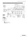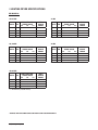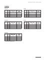
1
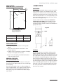
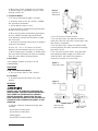
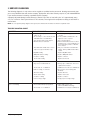
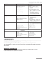
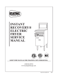
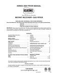
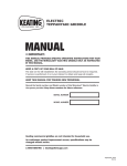
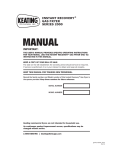
INSTANT RECOVERY ® ELECTRIC FRYER SERIES 2006 MANUAL IMPORTANT: THIS MANUAL PROVIDES SPECIFIC OPERATING INSTRUCTIONS FOR YOUR MODEL. USE THE INSTANT RECOVERY® ELECTRIC FRYER ONLY AS INSTRUCTED IN THIS MANUAL. KEEP A COPY OF YOUR BILL OF SALE. The date on the bill establishes the warranty period should service be required. If service is performed, it is in your interest to obtain and keep all receipts. KEEP THIS MANUAL FOR TRAINING NEW PERSONNEL. Record the Serial number and Model number of this Instant Recovery® Electric Fryer in the spaces provided. Keep these numbers for future reference. SERIAL NUMBER MODEL NUMBER Keating commercial fryers are not intended for household use. As continuous product improvement occurs, specifications may be changed without notice. 1-800-KEATING | keatingofchicago.com Part # 057641 electricFryer2006 08/13 PURCHASER SHOULD POST IN A PROMINENT LOCATION. WARNING Gas Burns Shock Improper installation can cause damage, injury or death. Improper installation, adjustment, alteration, service or maintenance can cause property damage, injury or death. Read the installation, operating and maintenance instructions thoroughly before installing or servicing this equipment. WARNING FOR YOUR SAFETY: Do not store or use gasoline or other flammable vapors or liquids in the vicinity of this or any other appliance. Do not store flammable liquids near this or any other appliance. THE EQUIPMENT IS TO BE INSTALLED TO COMPLY WITH THE BASIC PLUMBING CODE OF THE BUILDING OFFICIALS AND CODE ADMINISTRATORS INTERNATIONAL, INC. (BOCA) AND THE FOOD SERVICE SANITATION MANUAL OF THE FOOD AND DRUG ADMINISTRATION (FDA). 9902091 i 9902091 ELECTRIC FRYER - SERIES 2006 TABLE OF CONTENTS Important Safety Instructions ............................................ i Oil Breakdown ................................................................ 8 INTRODUCTION .............................................................. 1 Limited Calibration ..................................................... 8 - 9 INSTALLATION Thermostat Bulb Positioning............................................. 9 Damage During Shipment ................................................ 1 SERVICE DIAGNOSIS Standard Features ........................................................... 2 Troubleshooting Chart ............................................. 10 - 11 Safety Precautions .......................................................... 2 ORDERING PARTS Drop-In Fryer Counter Cut-Out/Installation ......................... 3 Service Parts Ordering .................................................. 11 FIRST STEPS Warning and Operating Plates ........................................ 11 Positioning ...................................................................... 3 PARTS LIST ........................................................... 12 - 20 Leveling .......................................................................... 3 Electric Fryer Parts List & Assembly ............................... 12 Restraining Devices ......................................................... 4 BB Control Panel Parts List ............................................ 13 Electrical Connection ....................................................... 4 TS Control Panel Parts List............................................. 14 OPERATING CPU Control Panel Parts List ................................... 16 - 18 Filling ............................................................................. 4 Basket-Lift Housing and Roller Guide Parts ............... 19 - 20 Melting .......................................................................... 5 WIRING DIAGRAMS ............................................... 21 - 35 Cooking ..................................................................... 5 - 6 Single Basket Lift Power Supply Box .............................. 21 Shutdown ....................................................................... 6 BB Wiring Diagram ................................................ 22 - 27 Draining.......................................................................... 6 TS Wiring Diagram .................................................. 27 - 34 Cleaning and Boil-Out ...................................................... 7 CPU Wiring Diagram ............................................... 34 - 35 Electronic Timers ............................................................ 8 FRYER SPECIFICATIONS PREVENTATIVE MAINTENANCE BB Models .................................................................... 36 Warranty Repairs ............................................................. 8 TS Models .................................................................... 37 Preventive Maintenance Chart ......................................... 8 Warranty Information ..................................................... 38 INTRODUCTION Instructions in this manual should be read thoroughly before attempting to operate this Keating Electric Fryer. All installation and service on Keating equipment must be performed by qualified, certified, licensed and/or authorized installation or service personnel. Operating information for Keating equipment has been prepared for use by qualified and/or authorized personnel. Keating equipment is made in the USA and has American sizes of hardware. All metric conversions are approximate. INSTALLATION INSTRUCTIONS Keating does not assume responsibility for loss or damage incurred in transit. chandise has been unpacked. The contents may be damaged in transit due to rough handling even though the carton may not show external damage. When the damage is discovered upon unpacking, make a written request for inspection by the carrier’s agent within fifteen days of the delivery date. Then file a claim with the carrier since such damage is the carrier’s responsibility. By following these instructions carefully, we guarantee our full support of your claims to protect you against loss from concealed damage. IMPORTANT VISIBLE LOSS OR DAMAGE This merchandise has been thoroughly inspected and carefully packed before leaving our plant. Responsibility for its safe delivery was assumed by the carrier at the time of shipment. Claims for loss or damage to the contents should, therefore, be made upon the carrier, as follows: Any external evidence of loss or damage must be noted on the freight bill or express receipt, and signed by the carrier’s agent. Failure to adequately describe such external evidence of loss or damage may result in the carrier refusing to honor a damage claim. The form required to file such a claim will be supplied by the carrier. CONCEALED LOSS OR DAMAGE DO NOT RETURN DAMAGED MERCHANDISE TO KEATING. FILE YOUR CLAIM AS STATED ABOVE. Proper installation will assure top performance. Alterations of any kind to your equipment will void the warranty. Before uncrating, check equipment carefully for damage. IF EQUIPMENT ARRIVES DAMAGED Concealed loss or damage means loss or damage which does not become apparent until the mer- 1-800-KEATING | 1 STANDARD FEATURES • Highly polished stainless steel fryer vessel • Highly polished stainless steel front • Highly polished stainless steel elements • Highly polished stainless steel thermostat bulb • Highly polished stainless steel Hi-Limit sensor • True Cold Zone for proper sedimentation • Grid screen over elements • Melt cycle • 1" full port front drain valve on 10x11 and 14; 1-1/4" for 18 and larger CM Model: BB and TS Counter Model Fryers are equipped with all of the same features as the BB and TS Models respectively, but take up less than three square feet of counter space. The 10x11CM Model can cook up to 36 lbs. of frozen fries per hour and the 14CM Model can cook up to 72 lbs. per hour. CPU Model: CPU Model Fryers have the same input as the TS Models. The panel of switches and indicating lights are also the same. A programmable computer replaces the two timers and thermostat. A secondary thermostat, located in the fryer’s cabinet, permits frying without the computer. SAFETY PRECAUTIONS • High temperature limit control with manual reset • Patented accurate temperature control system ±7°F • Ideal 35" working height • One pair of split baskets or one full-size basket (18" model only) • Circuit breaker protection for 208-240V 10×11 to 34×24 Models STANDARD ACCESSORIES • Keating Klenzer Sample THIS SYMBOL WARNS YOU THAT SERIOUS BURNS OR OTHER INJURIES MAY RESULT IF SAFETY INSTRUCTIONS ARE NOT FOLLOWED. • This service manual should be retained in a safe place for future reference. The installation of your new fryer must conform to current codes, with the current National Electrical Codes and regulations as applicable. • Your ventilation hood, when installed, must conform to the current standards. • Drain clean out rod • You must maintain this appliance free and clear from combustibles. STANDARD FRYERS • Adequate clearance for servicing and proper operation must be maintained. Your fryer is designed to be serviced from the front. • Sizes: 10×11 to 34×24 • Oil capacity 30 to 210 pounds • NSF, ETL and ETLS listed • Keating commercial fryers are not intended for household use. MODEL VARIATIONS • ALWAYS instruct new employees on proper fryer operation. BB Model: BB Model Fryers feature Power On indicating light, a melt cycle and an electric stainless steel thermostat. The 14BB model can cook up to 72 lbs. of frozen fries or 75 lbs. of chicken per hour. • ALWAYS turn fryer off each night. TS Model: TS Model Fryers have the highest input of all Keating fryers. The TS Model features a melt cycle, an electric stainless steel thermostat, two electronic timers and three indicating lights which display the status of the fryer’s operation. The 14TS Model can cook up to 90 lbs. of frozen fries or 75 lbs. of chicken per hour. • NEVER leave a fryer unattended during operation. TS Basket-Lift Model: TS Basket-Lift Model Fryers come with all the same features as the TS Model. The Basket-Lift mechanism lowers the baskets of food into the oil when the timer button is pressed and raises the baskets when the cooking cycle is complete. Split baskets are used for all models. 2 | keatingofchicago.com • ALWAYS turn fryer off at customer power panel before servicing. • NEVER move a fryer when full of hot oil. • NEVER introduce objects or liquids into fryer, whil operational, which are not designed or made for cooking. • THIS FRYER MAY NOT BE ALTERED, MODIFIED OR CHANGED IN ANY WAY. ELECTRIC FRYER - SERIES 2006 FIRST STEPS DROP-IN FRYER COUNTER CUTOUT/INSTALLATION TYP. 45° “A” 5/8" 1/8" POSITIONING The fryer must be placed under an exhaust hood with a fire retardant system. Your ventilation hood, when installed, must conform to the current standards. ALL connections and placement must comply with current local and national codes. It is the responsibility of the owner and local installer to comply with these regulations when installing the fryer. DETERMINED BY CUTTING TOOL USED 5/8" CUT LINE “B” Counter model and floor model fryers must be restrained to prevent tipping when installed in order to avoid splashing, spilling, etc. of hot liquid. The restraining method may be a manner of installation or by separate means. 5/8" Figure 1 5/8" BEND UP 90° ON ALL SIDES TO FINAL OPENING SIZE (“A” X “B”), THEN CLOSE CORNERS BY WELDING AN INSERT PIECE (OR OTHER SUITABLE METHODS) FOR A LEAK FREE FIT. FRYER "A" LEVEL "B" 10x11 DI ELECTRIC 13" 22" 14 DI ELECTRIC 16" 23 1/2" 18 DI ELECTRIC 20" 29" INSTALLATION NOTES 1. All Drop-In Fryers must be 16" from any open flame. 2. Fryer must be located no more than 5" from counter top front. 3. Cabinet must be reinforced to support full weight of fryer in use (Fryer, oil, food, etc.). 4. Fryers must be properly ventilated and located under an exhaust hood. DROPPING THE FRYER INTO THE COUNTER TOP It is only necessary to place the fryer in such a position that the front edge overlaps the front raised edge of the opening. Push the fryer forward as far as it will go holding the fryer on approximately a 15° angle, and then drop the rear of the fryer into its proper position lowering it down gently so you do not deform the table or equipment stand. LEG CASTER LEVELING The fryer will operate at its highest efficiency when properly leveled. Place a level on fryer vessel from side to side. For fryers on legs, the bottom foot of the leg is adjustable. Looking from the bottom of the foot, turn clockwise to decrease height or counter clockwise to increase height until level. For fryers on casters, the casters are adjustable by loosening the jam nut and turning the caster in or out. When the desired level is reached, tighten the jam nut. Adjustments of more than 3/4" are not recommended on any caster. The same procedure should be followed to level the fryer from front to back. 1-800-KEATING | 3 NOTICE Restraining devices required. RESTRAINING DEVICES 1. Adequate means must be provided to limit the movement of the appliance without depending on the connector and the quick-disconnect device or its associated piping to limit the appliance movement. Fryer must also be restrained to prevent tipping when installed so that hot liquid splashing is avoided. NOTE: A hole has been punched in the rear of the fryer cabinet for a cord or conduit exit. If a cord is used, the National Electrical Code, ETL standards and most local codes require a bushing or strain relief (not provided by Keating) to protect the cord. WIRE SIZE TABLE Conductor Current (Amps up to) Recommended Wire Size (AWG) 15 14* 20 12* 30 10* 40 8 55 6 70 4 95 2 125 0 145 2/0 165 2/0** 190 2/0** 2. The restraint means must be attached to the rear of the Keating Electric Fryer within 2" of the center line width and approximately 1-5/8" from the bottom of the cabinet back to allow the restraining bolt to be anchored to the cabinet back between the cabinet bottom and inner liner. If disconnection of the restraint is necessary, it must be reconnected when the Keating Electric Fryer is returned to its originally installed position. ELECTRICAL CONNECTION The Keating Instant Recovery® Electric fryer is equipped with a three wire terminal block for customer connections. The terminal block is located behind the fryer door on the right side behind a panel (held in place by two screws). Compare the fryer terminal connections to the appropriate wiring diagram for the fryer (see pages 21 thru 35) to see if the fryer is connected three phase or single phase. All wires/cords, plugs, receptacles and circuit breakers must be sized adequately for the full load rating of the fryer as specified by local codes, or in the absence of local codes, by the current National and Canadian Electrical Codes as applicable. The Keating Electric Fryer is also equipped with a grounding lug next to the terminal block. For proper grounding procedures, see local codes or, in the absence of local codes, by the current National and Canadian Electrical Codes as applicable. NOTE: A copy of your wiring diagram is shipped with your equipment. NOTE: For fryers rated at 208-240 volts, the amperage ratings marked on the nameplates of the fryers are listed at 240 volts as required by ETL. If your fryer is to be fed by a 208 or 220 volt system, consult the Keating Fryer Specifications on pages 36 and 37 to determine the full load rating of the fryer. NOTE: Fryers with Safe & Easy® Filters (Model BBSE or TSSE) or Central Filters will have separate 120 volt control circuit connections. NOTE: A copy of your wiring diagram is located on the inside of the door. 4 | keatingofchicago.com *For runs greater than 75' up to 125', use the next wire size larger to keep the voltage drop to less than 3%. For runs greater than 125', consult the National Electrical Code Handbook to help determine the proper wire size. **2/0 wire ambient temperature must be kept at less than 104°F (40°C). OPERATING FILLING NOTE: Before filling the fryer make certain the fryer vessel is sanitized, dry and the drain valve is completely closed. Refer to figure 4 or 5 on page 6 for location of drain valve. BE SURE THE HEATING ELEMENTS ARE COMPLETELY COVERED WITH OIL BEFORE SWITCHING THE FRYER ON. IF OIL LEVEL DROPS BELOW TOP OF HEATING ELEMENTS, SEVERE DAMAGE TO FRYER AND INJURY TO OPERATOR MAY RESULT. WATER IN ANY FORM AND HOT OIL DON'T MIX! OIL EXPANDS WHEN HEATED. THE MAX LEVEL LINE HAS BEEN PROVIDED TO ENSURE OPTIMUM COOKING WHILE ENSURING THE SAFETY OF THE OPERATOR. DO NOT OVERFILL THE FRYER VESSEL. ELECTRIC FRYER - SERIES 2006 Figure 2 Fill Level Line OPERATION OF THIS FRYER SHOULD BE LIMITED TO PERSONNEL WHO HAVE BEEN THOROUGHLY TRAINED IN OPERATING PROCEDURES. USE ONLY KEATING APPROVED BASKETS IN YOUR FRYER. NEVER OVERFILL FRY BASKETS. DO NOT BANG BASKETS ON BASKET HANGERS OR FRYER VESSEL. BB & TS, CPU and Basket-Lift Models 1. Fill the fryer vessel with oil up to the “Max Level” line. 2. If using solid shortening, remove screen and firmly pack solid shortening between the heating elements. Proceed to Melting section for instructions on use of the melt cycle. MELTING The Keating Melt Cycle safely melts solid shortening in the fryer vessel without scorching. BEFORE APPLYING POWER TO THE FRYER, MAKE SURE THE ELECTRIC CONNECTIONS ARE SECURE AND THE FRYER HAS BEEN PROPERLY FILLED WITH OIL. A. BB, TS and Basket-Lift Models 1. Set the thermostat to the desired temperature. 2. If using solid shortening, set Melt-Fry switch to the “MELT” position. Stay in the “MELT” cycle until the shortening has melted completely and is at the “Max Level” line before switching to the “FRY” position for cooking. B. CPU Models *See separate computer instructions or call 1-800-KEATING. CARE SHOULD BE TAKEN WHEN LOWERING BASKETS INTO FRYER TO PREVENT SPLASHING HOT OIL FROM FRYER VESSEL. NEVER LIFT BASKETS DIRECTLY OUT OF THE FRYER VESSEL WITHOUT DRAINING AS SEVERE INJURY MAY RESULT. NOTE: For safety purposes, all Hi-Limit controls are manually reset. Always check the Hi-Limit reset button before attempting to use the fryer. If the Hi-Limit has tripped, the fryer will not operate. NOTE: For a fryer with a Central or Safe & Easy® Filter, always check the rear drain operating handle before attempting to use the fryer. A safety switch prevents the fryer from operating if the handle is not pushed in completely and locked into place. A. BB Models 1. Fill fryer as described on page 4-5 - FILLING. 2. Set Power switch to the “On” position. “POWER ON” light will be illuminated. 3. Set the Melt-Fry switch to “FRY.” 4. Set thermostat to the desired frying temperature (between 325°F and 335°F). 5. When the oil reaches the desired frying temperature, lower filled basket(s) slowly into the hot oil. 6. When cooking cycle is complete, carefully lift basket(s) out of oil. Place them on basket hanger (on splashback of fryer) to allow draining of excess oil. B. TS Model NOTE: During the “MELT” cycle, the elements are on for approximately 5-7 seconds and off for approximately 50 seconds. 1. Fill fryer as described on pages 4-5 - FILLING. COOKING 3. Set the Melt-Fry switch to “FRY.” Keating Instant Recovery® Electric Fryers are designed to provide maximum production efficiency and deliver high quality food products. Low-temperature cooking, highly polished stainless steel and a true COLD ZONE mean extended oil life. Follow cooking procedures for your model. 4. Set thermostat to the desired frying temperature (between 325°F and 335°F). 2. Set Power switch to the “On” position. “POWER ON” light will be illuminated. 5. When the oil reaches the desired frying temperature, the “READY TO COOK” light will illuminate. 6. Lower filled basket(s) slowly into the hot oil. 7. Set timer for left or right side basket, whichever is being lowered into oil. For programming instructions, see page 8. 1-800-KEATING | 5 8. When timer sounds, lift basket out of oil. Place on basket hanger (on splashback of fryer) to allow draining of excess oil. C. Basket-Lift Models Figure 3 Operator in Safety Gear 1. Fill fryer as described on page 4 - FILLING. 2. Set Power switch to the “On” position. “POWER ON” light will be illuminated. 3. Set the Melt-Fry switch to “FRY.” 4. Set thermostat to the desired frying temperature (between 325°F and 335°F). 5. When the oil reaches the desired frying temperature, the “READY TO COOK” light will illuminate. 6. Fill basket(s) to proper level and place on upper bar of lift rod(s). 7. Set timer(s) to desired cooking time. For programming timers see page 8. 8. Push “T1,” “T2” or “T3” buttons on timer(s). Basket(s) will automatically lower into fryer vessel. 9. When cooking cycle is complete, an audible alarm will sound and the basket(s) will raise automatically. Allow oil to drain before removing baskets. D. CPU Model *See separate computer instructions or call 1-800-KEATING. 2. Turn off the fryer and open the door. 3. For front drain fryers, put approved container under drain valve. For fryers with a central filter, slide filter drawer in completely. 4. For front drain fryers, slowly turn handle forward to avoid splashing. The drain valve will be completely open after 1/4 turn. 5. For units with rear drain valves, slowly pull drain valve operating handle straight out (unhook from metal latch first). See Safe & Easy operator’s manual for instructions on how to filter. Figure 4 Front Drain Valve SHUTDOWN A. BB, TS and Basket-Lift Models 1. Turn fryer Power switch to “OFF” position. B. CPU Model 1. Set Main Power On/Off switch to the “OFF” position. DRAINING ALWAYS SHUT THE FRYER OFF COMPLETELY BEFORE DRAINING. THE FRYER SHOULD BE DRAINED ONLY UNDER THE SUPERVISION OF PROPERLY TRAINED PERSONNEL. A DRAIN PIPE AND COVERED CONTAINER SUITABLE FOR USE WITH HOT OIL SHOULD BE USED TO ENSURE THE SAFETY OF THE OPERATOR. 1. Operator should be outfitted with proper attire including: – Oil and heat resistant gloves – Oil and heat resistant apron – Safety goggles – Oil and heat resistant footwear 6 | keatingofchicago.com Figure 5 Safe & Easy® Filter DRAIN VALVE Side view with filter in battery Side view with filter under ELECTRIC FRYER - SERIES 2006 UNDER NO CIRCUMSTANCES SHOULD YOU PERMIT HOT OIL TO COME IN CONTACT WITH WATER OR ICE. ALL DRAINING SHOULD BE DONE UNDER THE SUPERVISION OF PROPERLY TRAINED PERSONNEL. A DRAIN PIPE AND COVERED CONTAINER SUITABLE FOR USE WITH HOT OIL SHOULD BE USED WHENEVER A FRYER IS DRAINED. ALWAYS DRAIN OIL INTO A COVERED RECEPTACLE APPROVED FOR THE TRANSPORTATION OF HOT OIL. CLEANING AND BOIL OUT When cleaning and boiling out your fryer use Keating Sea Powder and Keating Klenzer to keep your fryer in top condition. Keating Sea Powder dissolves any grease build up - even carbonized grease in fryer vessels - one of the leading causes of premature oil breakdown. And once your fryer vessel is clean, use Keating Klenzer, the finest dry stainless steel polish available, to restore your Keating Instant Recovery® Electric fryers’ exterior to its original luster. To avoid damaging the fryer, do not power wash, spray or hose down unit while cleaning. Figure 6 Keating Klenzer and Sea Powder 8. Dissolve 2/3 cup of Keating Sea Powder for every five gallons of water and let soak for 1/2 hour. If there is a large build-up of carbonized grease, allow fryer to soak overnight. DO NOT DAMAGE OR REMOVE THERMOSTAT BULB AS THIS MAY AFFECT THE ACCURACY OF THE FRYER. 9. While soaking, a natural fiber brush may be used to scrub the inside walls of fryer. 10. Drain the water and Sea Powder into a dry, suitable receptacle and remove from cooking area. 11. Spread Keating Klenzer liberally on sides of fryer vessel. 12. At this point, a non-abrasive scouring pad may be used to remove the now softened carbonized grease. 13. Thoroughly rinse fryer vessel with potable water to remove all Klenzer. 14. Prior to refilling with oil, wipe the inside of the fryer vessel making sure all water and Klenzer has been removed. WATER IN ANY FORM AND HOT OIL DON'T MIX! 15. Close drain valve. FAILURE TO CLOSE DRAIN VALVE BEFORE REFILLING THE FRYER MAY RESULT IN SERIOUS INJURY. 1. Put on safety attire. See page 6 - DRAINING. 2. Turn the fryer off. 3. Drain oil from fryer, see page 6. Filtering may be done at this step. 4. Remove oil container to a secure area to prevent accidental spillage. 5. Fill fryer vessel to “Max Level” line with water. WHEN YOUR FRYER IS BEING USED IN CONJUNCTION WITH A CENTRAL FILTER, DISCONNECT POWER SUPPLY BEFORE RESETTING MOTOR TO PREVENT SERIOUS INJURY WHEN RESET SWITCH IS ENGAGED (SEE FILTER MANUAL). 16. Check thermostat bulb positioning - see page 9. 17. Refill the fryer with new or filtered oil. UNDER NO CIRCUMSTANCES SHOULD THE FRYER BE LEFT UNATTENDED DURING BOIL-OUT. TRAINED PERSONNEL MUST BE PRESENT DURING THE PROCEDURE TO PREVENT BOIL OVER OR TO TURN OFF THE POWER IF WATER DROPS BELOW HEATING ELEMENTS. NOTE: MSDS Sheets for Keating Klenzer, Sea Powder & Acidox are available on-line at www.keatingofchicago.com. 6. Set thermostat and turn fryer on to bring water to a gentle boil. 7. Once boil has been reached, turn fryer off. 1-800-KEATING | 7 ELECTRONIC CONTROL TIMERS MAINTENANCE The electronic timers provide a clearly visible and accurate display and are very easy to use. WARRANTY REPAIRS Figure 7 Electric Timer Keating’s warranty begins with the date of installation. In the event that your Instant Recovery® Fryer, under warranty, needs repairs other than routine maintenance or cleaning, you are required to contact Keating of Chicago (at 1-800-KEATING) before calling a local service company. PREVENTIVE MAINTENANCE PROGRAMMING To program the timers, the unit must be in the idle mode. Press and hold the set button for approximately two seconds. The display will show “SEt”. Press T1, T2, or T3 for the cook time to be programmed. The display will show the current setting for that cook time. Use the up or down button to increment or decrement the setting. When the setting is correct, press and hold the set button again for approximately two seconds. The display will show "StO" for approximately two seconds and the timer will return to normal operation. Repeat the process as necessary for the other timers. OPERATING LOGIC When the timer is powered up, the display will show the time setting for the cook time that was operated last and the relay output contacts will be open. To start a cycle, press the desired cook time button (T1, T2, T3). The display will begin to countdown from the preset time setting and the relay output contacts will close. During the countdown the colon will flash at a one-second rate. When the countdown has reached "00:00" the relay output contacts will open, the display will flash, and the audible alarm will sound. To cancel the audible alarm, press any button. Preventive maintenance should be done in daily, weekly, monthly and yearly intervals as necessary. Following preventive maintenance procedures will help keep your fryer working efficiently. Proper care and servicing will lead to years of quality performance. TIME FRAME OPERATOR/OWNER AT LEAST DAILY* • Check that the oil is up to “Max Level” line. • Clean all baskets. • Drain, strain or filter oil. AT LEAST WEEKLY* • Drain and clean fryer. • Boil-out fryer. AT LEAST MONTHLY* TIME FRAME AT LEAST YEARLY* • • • • Check lights and controls. Verify Thermostat settings. Test Hi-Limit control. Verify wire connections. QUALIFIED SERVICE PERSONNEL • Calibrate thermostat. *High production facilities should be checked more often. Contact the factory or a local service company to perform maintenance and repairs. Oil Breakdown PAUSE FEATURE To pause a cycle in progress, press any button. The relay output contacts will open, the display will flash, and the countdown will pause. To resume the countdown, press any button. The display will resume the normal countdown and the relay output contacts will close. As part of a “Preventive Maintenance Program”, the oil in your fryer needs to be filtered regularly to avoid breakdown. The initial investment in the frying system is less than the total overall costs of oil during the life of the fryer, and with regular filtering, you can realize substantial savings in oil costs as well as maintenance charges. CANCELING A CYCLE LIMITED CALIBRATION To cancel a cycle in progress press and hold any button for approximately two seconds. The relay output contacts will open and the display will show the time setting for the cook time last used. (Less than 15° difference) 8 | keatingofchicago.com Thermostat knob removed to reveal calibration screws ELECTRIC FRYER - SERIES 2006 You will need: One standard flat blade screwdriver One accurate fryer thermometer 1. Set thermostat to desired frying temperature. 2. Allow thermostat to cycle three times. 2. Allow fryer to cycle three times. 3. Place an accurate thermometer in the oil. 4. If temperature of fryer is found to be more or less than 15°F off, remove the thermostat knob. There are (4) screws holding the dial plate in place. Loosen the screws and reset the dial plate to match the thermometer reading. DO NOT ADJUST THE THERMOSTAT SET SCREW - IT VOIDS ANY WARRANTY ON PART. NOTE: Locate thermometer in same position for every calibration. Position next to upper heating element is recommended. Thermostat Bulb Positioning Keating’s patented thermostat application is accurate within ±7°F of the dial setting between 250°F and 350°F. This accuracy is attained only if the thermostat bulb is placed properly against the top element using element clamps. If the bulb is too far away from the element, the fryer will overshoot. Overshoot: The thermostat takes a long time to cycle and then misses its preset temperature by 20°F 40°F yielding a poor quality product. 1-800-KEATING | 9 SERVICE DIAGNOSIS The following diagnosis is only to be used as a guide to qualified service personnel. Keating recommends that you use a qualified & licensed service company. (Equipment still under warranty requires it.) Call 1-800-KEATING if you need assistance in locating a qualified service company. A properly adjusted Keating Instant Recovery® Electric Fryer, with no load, will cycle “on” approximately every 2 1/2 to 3 minutes. Each cycle will last 15 -25 seconds, ensuring that the temperature setting is held within a narrow band. NOTE: To correctly and quickly diagnose the system, the chart below should be followed in sequential order. TROUBLE SHOOTING CHART PROBLEM PROBABLE CAUSE SOLUTION Fryer won't heat a. No electricity to fryer (“POWER ON” switch is off). b. No electricity to control circuit (models with Basket-Lift or Central Filter). c. Fryer circuit breakers have tripped. d. Hi-Limit has been activated. a. Connect fryer to an approved source of power. b. Connect 120V terminal block to an approved source of power. c. Reset circuit breakers. d. Push in Hi-Limit Reset button located behind fryer door. Check calibration of thermostat and operation of Hi-Limit and contactor. e. Fully close and latch rear drain valve handle. Turn fryer OFF and then ON to restart. e. Rear drain valve handle has not been fully closed (fryers with filter only). f. ON/OFF is faulty. Fryer has poor recovery or runs cold Fryer is overheating 10 | keatingofchicago.com g. MELT/FRY switch is faulty. h. Contactor is faulty. i. Thermostat is faulty. f. Replace ON/OFF switch. g. Replace MELT/FRY switch. h. Replace contactor. i. Replace thermostat. a. Over-filling baskets. a. Don’t overfill baskets. b. Fryer vessel overfilled with oil. b. Fill fryer up to “Max Level” line as oil expands when heated. c. Thermostat out of calibration. c. Calibrate thermostat. (See Calibration). d. Carbon coating on elements. d. Boil-out fryer. (See Cleaning and Boil-Out). e. Element is faulty. e. Replace Element. f. Thermostat is faulty. f. Replace thermostat. g. Contactor is faulty. g. Replace contactor. h. Low incoming voltage. h. Verify proper incoming voltage. a. Thermostat bulb improperly placed. a. Adjust bulb position. (See Thermostat Bulb Positioning). b. Thermostat out of calibration. b. Calibrate thermostat (See Calibration). ELECTRIC FRYER - SERIES 2006 PROBLEM PROBABLE CAUSE SOLUTION Oil in fryer vessel smokes a. Oil has begun to break down. b. High carbon content in oil. a. Replace oil. c. Dirty fryer vessel. d. Inferior grade of oil. e. Fryer is overheating. Oil in fryer vessel boils over Contactor chatters b. Filter oil completely, replace if necessary. c. Boil-out fryer. See Cleaning and Boil-Out. d. Check with oil supplier for higher grade of oil needed for your cooking applications. e. Check calibration of thermostat (See Calibration) and replace if necessary. Check if Hi-Limit trips at 425°F. If not, replace Hi-Limit. a. Baskets are overfilled. a. Don’t overfill baskets. b. Fryer vessel overfilled with oil. b. Fill fryer up to “Max Level” line as oil expands when heated. c. Oil is breaking down and foaming. c. Replace oil. d. Water in cold zone. d. Stir oil with a paddle until water boils off. Filter oil. If water remains, let oil cool and drain a quart of it. a. Voltage is low to fryer. a. Contact your electrician or the local power company and have the incoming power checked. b. Contactor coil faulty. b. Replace contactor. c. Connections are loose. c. Tighten connections. d. Thermostat contacts do not close properly. d. Replace thermostat. TS MODELS Basket-Lift mechanism will not operate a. Connections are loose or timer is faulty. a. Tighten connections. Replace timer if it will not operate. b. Actuator is faulty. b. Replace actuator. c. Control circuit breaker has tripped. c. Reset circuit breaker. d. Relay is faulty. d. Replace relay. ORDERING PARTS Parts may be ordered by calling 1-800-KEATING or your local Keating service company. You may also order on-line at Keating’s part store, www.keatingofchicago.com Refer to the Keating Electric Fryer Limited Warranty for complete service and ordering information. The model/serial plate is attached to the inside of the front door. The serial and model numbers are necessary when ordering. WARNING AND OPERATING PLATES All warning and operating plates on the Instant Recovery® Electric Fryer should be in place at all times. If plates are damaged or lost, replace them immediately. 1-800-KEATING | 11 PARTS LIST - ELECTRIC FRYER ITEM DESCRIPTION P/N 220V ELEMENT MODEL P/N 440V ELEMENT 10x11 14 18 20 24 34x24 4 5 5 6 Quantity Per Model 1 HEATING ELEMENT 2500 W 3800 W 4350 W 6000 W 6500 W TEFLON RING 5/8" FLAT WASHER 5/8" - 16 BRASS LOCKNUT LCKWSHR, INT #10 H-TEMP RING TERM #10 HI-TEMP FLAT WASHER #10 HI-TEMP NUT 10-32 ITEM DESCRIPTION BB BB TS BB BB TS BB TS TS BB, TS BB, TS BB, TS BB, TS BB, TS BB, TS BB, TS 004347 005623 004349 004353 004353 004355 004355 014493 004318 004319 004323 011562 011881 059502 000361 MODEL 3 3 3 006342 004348 004350 004352 004352 022287 022287 019256 004318 004319 004323 011562 011881 059502 000361 P/N 3 3 4 3 4 3 2 Per Element 2 Per Element 2 Per Element 2 Per Element 2 Per Element 2 Per Element 2 Per Element 10x11 14 18 20 24 34x24 Quantity Per Model 2 3 4 5 6 ITEM 6 ELEMENT CLAMP ELEMENT SPACER FRYER VESSEL DRAIN VALVE, FRONT 1" DRAIN VALVE, REAR 1" DRAIN VALVE, FRONT 1 1/4" DRAIN VALVE, REAR 1 1/4" DRAIN VALVE, FRONT 2" BASKET HANGER DESCRIPTION BASKET HANGER ALL ALL 004167 004145 CALL 1-800-KEATING BB, TS 004553 BB, TS 016341 BB, TS 004554 BB, TS 016342 OPTIONAL 019722 SEE BELOW 2 2 1 1 1 1 1 1 1 2 4 1 2 4 1 2 2 1 1 1 1 1 1 1 1 1 1 1 1 1 1 2 2 2 10x11 14 18 20 24 018553 018477 018556 018559 018562 6 Splashback 1 1 3 4 1 2 Exploded view of heating element wire connection hardware 12 | keatingofchicago.com 5 ELECTRIC FRYER - SERIES 2006 BB CONTROL PANEL 208/240V & 480V 1 Control Panel Front (not shown to scale) 2 3 Detail Area 4 12 7 8 Contactor Tray (Top View) Front Drain Unit 5 6 9 13 10 Contactor Tray (Front View) Front Drain Unit 11 ITEM DESCRIPTION P/N 10x11 14 18 20 24 34x24 Quantity Per Model 1 2 3 4 5 6 7 8 9 10 11 12 13 SWITCH TOGGLE SEALED ON-OFF INDICATING LIGHT CLEAR ROUND 28V SWITCH TOGGLE SEALED MELT-FRY THERMOSTAT KNOB, BLACK THERMOSTAT DIAL PLATE FRYER 250º-375º THERMOSTAT CONTACTOR 3 POLE 30 AMP CONTACTOR 3 POLE 40 AMP CONTACTOR 3 POLE 50 AMP CONTACTOR 4 POLE 40 AMP TRANSFORMER STEP DOWN FAT MELT INFINITE CONTROL HIGH LIMIT RESETTABLE CIRCUIT BREAKER 16 AMP 1 POLE (208-240V) CIRCUIT BREAKER 32 AMP 1 POLE (208-240V) CIRCUIT BREAKER 40 AMP 1 POLE (208-240V) CIRCUIT BREAKER 10 AMP 1 POLE (480V) CIRCUIT BREAKER 16 AMP 1 POLE (480V) CIRCUIT BREAKER 20 AMP 1 POLE (480V) MAGNETIC REED SWITCH (Rear Drain Fryers Only) RELAY (Rear Drain Fryers Only) 059141 057863 059143 060612 058037 031099 033896 033898 033899 053383 056037 037470 060806 057338 033885 033881 057336 057338 033920 053777 030844 1 1 1 1 1 1 (2082 480V) 1 1 1 3 1 1 1 1 1 1 2(480V) 2 1 1 1 1 1 1 1 1 1 2(480V) 1 1 1 1 1 1 2(480V) 2 2 1 1 1 1 1 1 1 1 1 1 1 1 4 (480V) 4 1 1 1 1 1 1 2(480V) 1 1 1 6 6 8 10 6 1 1 6 1 1 8 1 1 10 2 1 1 1 1 6 3 6 1 1 1 1 1-800-KEATING | 13 TS CONTROL PANEL 208/240V & 480V with ROCKER SWITCHES (not shown to scale) Control Panel Front 1 5 10 14 6 5 11 12 Contactor Tray (Top View) Front Drain Unit ITEM 4 8 7 9 3 2 DESCRIPTION Contactor Tray (Front View) Front Drain Unit P/N 10x11 14 18 20 13 24 34x24 Quantity Per Model 1 2 3 4 5 6 7 8 9 10 11 12 13 14 15* 16* SWITCH ROCKER ON-OFF DPST SWITCH ROCKER SPDT WHITE INDICATING LIGHT GREEN 28V INDICATING LIGHT RED 28V TIMER DIGITAL 24V/120VAC THERMOSTAT KNOB, BLACK THERMOSTAT DIAL PLATE FRYER 250º-375ºP THERMOSTAT FAT MELT INFINITE CONTROL CONTACTOR 3 POLE 30 AMP CONTACTOR 3 POLE 50 AMP CONTACTOR 4 POLE 30 AMP CONTACTOR 4 POLE 40 AMP TRANSFORMER STEP DOWN 24VAC 75VA HIGH LIMIT RESETTABLE CIRCUIT BREAKER 16 AMP 1 POLE (208-240V) CIRCUIT BREAKER 25 AMP 1 POLE (208-240V) CIRCUIT BREAKER 32 AMP 1 POLE (208-240V CIRCUIT BREAKER 40 AMP 1 POLE (208-240V) CIRCUIT BREAKER 13 AMP 1 POLE (480V) CIRCUIT BREAKER 20 AMP 1 POLE (480V) RELAY MAGNETIC REED SWITCH CIRCUIT BREAKER BASKET LIFT 4AMP 1 POLE *Not Shown, Rear Drain Fryers Only 14 | keatingofchicago.com 035030 025726 021255 021209 056921 060612 058037 031099 037470 033896 033899 053385 053383 056037 060806 057338 033525 033885 033881 057337 033920 030844 053777 058219 1 1 1 1 2 1 1 1 1 (2082 480V) 1 1 1 1 1 1 2 1 1 1 1 2 (480V) 2 1 1 1 1 2 1 1 1 1 1 1 1 1 2 1 1 1 1 1 1 1 1 2 1 1 1 1 4 (480V) 4 1 1 2 (480V) 2 1 1 2 (480V) 2 1 1 1 1 6 8 8 10 6 1 1 1 8 2 1 1 8 2 1 1 10 1 1 1 1 1 1 1 2 1 1 1 1 4 (480V) 4 1 1 3 3 1 1 12 1 2 ELECTRIC FRYER - SERIES 2006 TS CONTROL PANEL 208/240V & 480V with TOGGLE SWITCHES (not shown to scale) 1 2 3 4 5 059870 8 9 Detail Area Control Panel Front 6 10 7 11 15 6 12 13 Contactor Tray (Top View) - Front Drain Unit ITEM DESCRIPTION 14 Contactor Tray (Front View) - Front Drain Unit P/N 10x11 14 18 20 24 Quantity Per Model 1 2 3 4 5 6 7 8 9 10 11 12 13 14 15 16* 17* SWITCH TOGGLE SEALED ON-OFF INDICATING LIGHT CLEAR ROUND 28V SWITCH TOGGLE SEALED MELT-FRY INDICATING LIGHT GREEN ROUND INDICATING LIGHT RED ROUND TIMER DIGITAL 24V/120V THERMOSTAT KNOB, BLACK THERMOSTAT DIAL PLATE FRYER 250º-375º THERMOSTAT FAT MELT INFINITE CONTROL CONTACTOR 3 POLE 30 AMP CONTACTOR 3 POLE 50 AMP CONTACTOR 4 POLE 30 AMP CONTACTOR 4 POLE 40 AMP TRANSFORMER STEP DOWN 24VAC 75VA HIGH LIMIT RESETTABLE CIRCUIT BREAKER 16 AMP 1 POLE (208-240V) CIRCUIT BREAKER 25 AMP 1 POLE (208-240V) CIRCUIT BREAKER 32 AMP 1 POLE (208-240V) CIRCUIT BREAKER 40 AMP 1 POLE (208-240V) CIRCUIT BREAKER 13 AMP 1 POLE (480V) CIRCUIT BREAKER 20 AMP 1 POLE (480V) RELAY MAGNETIC REED SWITCH CIRCUIT BREAKER BASKET LIFT 4AMP 1 POLE 059141 057863 059143 056587 057861 056921 060612 058037 031099 037470 033896 033899 053385 053383 056037 060806 057338 033525 033885 033881 057337 033920 030844 053777 058219 1 1 1 1 1 2 1 1 1 1 (2082 480V) 1 1 1 1 1 1 1 2 1 1 1 1 2 (480V) 2 1 1 1 1 1 2 1 1 1 1 1 1 1 1 1 2 1 1 1 1 1 1 1 1 1 2 1 1 1 1 4 (480V) 4 1 1 2 (480V) 2 1 1 2 (480V) 2 1 1 1 1 6 8 8 10 6 1 1 1 8 2 1 1 8 2 1 1 10 1 1 1 3 3 1 1 *Not Shown, Rear Drain Fryers Only 1-800-KEATING | 15 34x24 TS CONTROL PANEL 208/240V & 480V with TOGGLE SWITCHES (not shown to scale) 1 3 2 6 4 7 Control Panel Front 5 6 10 Detail Area Contactor Tray (Top View) Front Drain Unit 11 15 11 13 12 Contactor Tray (Front View) Front Drain Unit 8 9 ITEM DESCRIPTION 1 2 3 4 5 6 7 8 9 10 11 12 13 14 15 16* 17* SWITCH TOGGLE SEALED ON-OFF INDICATING LIGHT CLEAR ROUND 28V SWITCH TOGGLE SEALED MELT-FRY INDICATING LIGHT GREEN ROUND INDICATING LIGHT RED ROUND TIMER DIGITAL 24V/120V THERMOSTAT KNOB, BLACK THERMOSTAT DIAL PLATE FRYER 250º-375º THERMOSTAT FAT MELT INFINITE CONTROL CONTACTOR 3 POLE 30 AMP CONTACTOR 3 POLE 50 AMP CONTACTOR 4 POLE 30 AMP CONTACTOR 4 POLE 40 AMP TRANSFORMER STEP DOWN 24VAC 75VA HIGH LIMIT RESETTABLE CIRCUIT BREAKER 16 AMP 1 POLE (208-240V) CIRCUIT BREAKER 25 AMP 1 POLE (208-240V) CIRCUIT BREAKER 32 AMP 1 POLE (208-240V) CIRCUIT BREAKER 40 AMP 1 POLE (208-240V) CIRCUIT BREAKER 13 AMP 1 POLE (480V) CIRCUIT BREAKER 20 AMP 1 POLE (480V) RELAY MAGNETIC REED SWITCH CIRCUIT BREAKER BASKET LIFT 4AMP 1 POLE *Not Shown, Rear Drain Fryers Only 16 | keatingofchicago.com 14 P/N 059141 057863 059143 056587 057861 056921 060612 058037 031099 037470 033896 033899 053385 053383 056037 060806 057338 033525 033885 033881 057337 033920 030844 053777 058219 34x24 1 1 1 1 1 2 1 1 1 1 4 (480V) 4 1 1 12 1 2 ELECTRIC FRYER - SERIES 2006 34x24 CPU CONTROL PANEL 208/240V with TOGGLE SWITCH (not shown to scale) Control Panel Front 3 2 1 9 10 9 Detail Area Contactor Tray (Top View) Rear Drain Unit 4 11 7 8 6 6 Contactor Tray (Front View) - Rear Drain Unit ITEM 1 2 3 4 5 6 7 8 9 10 11 DESCRIPTION SWITCH TOGGLE SEALED ON-OFF COMPUTER INDICATING LIGHT RED ROUND TRANSFORMER STEP DOWN 24VAC 75VA CIRCUIT BREAKER 40 AMP 1 POLE (208-240V) HIGH LIMIT RESETTABLE RELAY DPDT 24 VAC RELAY DPDT 24 VDC MAGNETIC REED SWITCH COMPUTER PROBE CONTACTOR 50 AMP 3 POLE 5 P/N 34x24 059141 031125 057861 056037 033881 060806 030844 017673 053777 004776 033899 1 1 1 1 12 1 1 1 2 1 4 1-800-KEATING | 17 CPU CONTROL PANEL 208/240V with ROCKER SWITCHES (not shown to scale) Control Panel Front 1 4, 5, 6, 7 8 2 3 14 Contactor Tray (Top View) 13 17 15 12 Spark Ignition Contactor Tray (Top View) 11 13 9 12 Contactor Tray (Front View) Rear Drain Unit Spark Ignition Contactor Tray (Front View) Rear Drain Unit 10 18 19 20 ITEM 16 20 DESCRIPTION 1 COMPUTER 2 SWITCH ROCKER ILLUMINATED GREEN 3 SWITCH ROCKER MOMENTARY 4 SCREW CARRIAGE 10 - 24 x 1/2" 5 WASHER INTERNAL TOOTH LOCK #10 6 WASHER .190 I.D. X .563 O.D. 7 NUT HEX #10 - 24 8 SCREW PAN HEAD PHILLIPS 10 - 24 x 1/2" 9 TRANSFORMER STEP DOWN 24VAC 80VA 10 CIRCUIT BREAKER 3 AMP 1 POLE (250V) 11 HIGH LIMIT MANUAL RESET 12 RELAY DPDT 24VAC 13 RELAY DPDT 24VDC 14 COMPUTER PROBE 15 TRANSFORMER STEP DOWN 24VAC 75VA 16 CIRCUIT BREAKER 40 AMP 1 POLE (208-240V) 17 CONTACTOR 50 AMP 1 POLE 18* SPARK IGNITION MODULE 24VAC 19* BRACKET SPARK IGNITION MODULE 20** MAGNETIC REED SWITCH *Spark Ignition Model Only **Rear Drain Fryers Only 18 | keatingofchicago.com 14 11 P/N QTY 031125 032242 015384 027490 011562 013217 009053 030850 024032 053338 060806 030844 017673 004776 056037 033881 033899 058439 056000 053777 1 1 1 4 4 4 4 2 1 1 1 2 2 1 1 6 2 1 1 1 ELECTRIC FRYER - SERIES 2006 BASKET LIFT POWER SUPPLY BOX & BASKET LIFT ASSEMBLY Basket Lift Power Supply Box Top View Basket Lift Assembly Side View 5 2 10 4 3 6 9 15 1 Housing 11 8 12 14 13 Top View 7 Bottom View NOTES: 1. A minimum distance of 3/16" and maximum distance of 1/4" should be maintained when actuator is at full downward stroke. Item 11 should never be bottomed on item 12 when in this location. 2. Actuator shaft should travel 6 1/2" upward from lowest position. 3. Distance is to be measured when actuator is powered. 4. Apply light coating of food grade grease to Item 9 on entire shaft inside housing. ITEM 1 2* 3 4 5 6 7 8 9 10 11 12 13 14 DESCRIPTION TRANSFORMER 120/208/240/480V CIRCUIT BREAKER 3A/250V RELAY DPDT 24V AC RECTIFIER POWER CORD CONNECTION 3 CIRCUITS PLUG CONNECTOR CONTACT PIN MALE CONNECTOR 2 CIRCUIT CAP CONNECTOR CONTACT PIN FEMALE COVER FOR CIRCUIT BREAKER PUSH ROD SCREW 1/4"-20" X 11/4" HEX NUT 1/4-20 COUPLER ACTUATOR BL RETAINING RING PIN COUPLER ACTUATOR BL ACTUATOR 24V DC SHAFT ACTUATOR LOWER BL S/S CONNECTOR 2 CIRCUIT PLUG CONNECTOR CONTACT PIN MALE PIN BASKET LIFT NON ROTATIONAL 15 *This circuit breaker can be found under the control panel on newer units. P/N QTY 056036 053338 030844 018321 021289 032210 028309 032207 028308 054664 018096 021091 016383 054525 054540 054503 054510 054522 032208 028309 054760 1 1 2 1 1 1 3 2 2 1 1 1 1 1 2 2 1 1 1 2 1 1-800-KEATING | 19 BASKET LIFT POWER SUPPLY BOX 2007 (CPU & NON-CPU) Top View 3 4 4 5 1 2 Side View ITEM 1 2 DESCRIPTION TRANSFORMER STEPDOWN 24VAC 100VA RELAY DPDT 24VAC RELAY DPDT 24VDC (CPU MODEL) RECTIFIER 24VDC BUSHING STRAIN RELIEF 5/8" HOLE BUSHING STRAIN RELIEF 3/4" HOLE 3 4 5 NOTE: Circuit breaker is located under the control panel. 20 | keatingofchicago.com P/N QTY 058359 030844 017673 018321 000470 033800 1 2 2 1 2 1 ELECTRIC FRYER - SERIES 2006 WIRING DIAGRAMS NOTE: A separate wiring diagram has been included with this manual and should be saved for troubleshooting and maintaining the fryer. The wiring diagrams in this section cover standard fryers which may or may not match the diagram sent with the fryer. CPU models on pages 34 & 35. SINGLE BASKET LIFT POWER SUPPLY BOX ITEM 1 2 3 DESCRIPTION AR WIRENUT GRAY AP CONNECTOR 6 CIRCUIT PLUG CONNECTOR CONTACT PIN MALE P/N QTY 027134 028302 028309 2 1 5 1-800-KEATING | 21 10x11, 14, 18 & 20 BB 2000 208240V & 480V 3 PHASE with REAR DRAIN & SAFE & EASY® FILTER WIRE COLOR CODES: BL - BLACK BR - BROWN BU - BLUE GR - GREEN OR - ORANGE RD - RED WH - WHITE YL - YELLOW 10x11 BB 2006 208-240V & 480V 3 PHASE FRONT DRAIN WIRE COLOR CODES: BL - BLACK BR - BROWN BU - BLUE GR - GREEN OR - ORANGE RD - RED WH - WHITE YL - YELLOW COMPONENT CODES: CB - CIRCUIT BREAKER CR - CONTACTOR 24VAC DB - POWER DISTRIBUTION BLOCK FM - FAT MELT TIMER SWITCH GRD - GROUNDING LUG H - HEAT ON LIGHT HL - HIGH LIMIT SWITCH MF - MELT FRY SWITCH P - POWER SWITCH PO - POWER ON LIGHT (CLEAR) TH - THERMOSTAT TR - TRANSFORMER 22 | keatingofchicago.com NOTES: 1. WIRES #1 TO #6 ARE 10 AWG #7 TO #15 ARE 12 AWG 2. ALL OTHER WIRES ARE 18 AWG COMPONENT CODES: CB - CIRCUIT BREAKER CR - CONTACTOR 24VAC GRD - GROUNDING LUG H - HEAT ON LIGHT HL - HIGH LIMIT SWITCH HLT - HIGH LIMIT TEST SWITCH MIF - MELT-IDLE-FRY SWITCH MP - MAIN POWER SWITCH R - RELAY 24VAC RDS - REAR DRAIN VALVE SWITCH RP - RECEPTACLE WITH POWER CORD (APPLIES ONLY TO UNITS WITH FILTER) TB - TERMINAL BLOCK TH - THERMOSTAT TR - TRANSFORMER TS - FAT MELT TIMER RELAY SWITCH ELECTRIC FRYER - SERIES 2006 10x11 BB 2006 208-240V & 480V 1 PHASE FRONT DRAIN WIRE COLOR CODES: BL - BLACK BR - BROWN BU - BLUE GR - GREEN OR - ORANGE RD - RED WH - WHITE YL - YELLOW COMPONENT CODES: CB - CIRCUIT BREAKER CR - CONTACTOR 24VAC DB - POWER DISTRIBUTION BLOCK FM - FAT MELT TIMER SWITCH GRD - GROUNDING LUG HL - HIGH LIMIT SWITCH MF - MELT FRY SWITCH P - POWER SWITCH PO - POWER ON LIGHT (CLEAR) TH - THERMOSTAT TR - TRANSFORMER NOTES: 1. WIRES #1 TO #6 ARE 10 AWG #7 TO #15 ARE 12 AWG 2. ALL OTHER WIRES ARE 18 AWG 10x11 BB 2006 208-240V & 480V 3 PHASE with REAR DRAIN WIRE COLOR CODES: BL - BLACK BR - BROWN BU - BLUE GY - GRAY GR - GREEN OR - ORANGE RD - RED WH - WHITE YL - YELLOW COMPONENT CODES: CB - CIRCUIT BREAKER CR - CONTACTOR 24VAC DB - POWER DISTRIBUTION BLOCK FM - FAT MELT TIMER SWITCH GRD - GROUNDING LUG HL - HIGH LIMIT SWITCH MF - MELT FRY SWITCH P - POWER SWITCH PO - POWER ON LIGHT (CLEAR) R - RELAY 24VAC RDS - REAR DRAIN VALVE SWITCH TH - THERMOSTAT TR - TRANSFORMER NOTES: 1. WIRES #1 TO #6 ARE 10 AWG #7 TO #15 ARE 12 AWG 2. ALL OTHER WIRES ARE 18 AWG 1-800-KEATING | 23 14, 18, 20 BB 2006 208-240V & 480V 1 PHASE FRONT DRAIN WIRE COLOR CODES: BL - BLACK BR - BROWN BU - BLUE GR - GREEN OR - ORANGE RD - RED WH - WHITE YL - YELLOW COMPONENT CODES: CB - CIRCUIT BREAKER CR - CONTACTOR 24VAC DB - POWER DISTRIBUTION BLOCK FM - FAT MELT TIMER SWITCH GRD - GROUNDING LUG HL - HIGH LIMIT SWITCH MF - MELT FRY SWITCH P - POWER SWITCH PO - POWER ON LIGHT (CLEAR) TH - THERMOSTAT TR - TRANSFORMER NOTES: 1. WIRES #1 TO #18 ARE 10 AWG 2. ALL OTHER WIRES ARE 18 AWG 14, 18, 20 BB 2006 208-240V & 480V 3 PHASE FRONT DRAIN COMPONENT CODES: CB - CIRCUIT BREAKER CR - CONTACTOR 24VAC DB - POWER DISTRIBUTION BLOCK FM - FAT MELT TIMER SWITCH GRD - GROUNDING LUG 24 | keatingofchicago.com HL MF P PO TH TR - HIGH LIMIT SWITCH MELT FRY SWITCH POWER SWITCH POWER ON LIGHT (WHITE) THERMOSTAT TRANSFORMER WIRE COLOR CODES: BL - BLACK BR - BROWN BU - BLUE GR - GREEN OR - ORANGE RD - RED WH - WHITE YL - YELLOW NOTES: 1. WIRES #1 TO #18 ARE 10 AWG FOR 208/240 VOLT UNITS, AND ARE 12 AWG FOR 480 VOLT UNITS 2. ALL OTHER WIRES ARE 18 AWG ELECTRIC FRYER - SERIES 2006 14, 18, 20 BB 2006 208-240V & 480V 3 PHASE with REAR DRAIN & SAFE & EASY® FILTER WIRE COLOR CODES: BL - BLACK BR - BROWN BU - BLUE GR - GREEN OR - ORANGE RD - RED WH - WHITE YL - YELLOW COMPONENT CODES: CB - CIRCUIT BREAKER CR - CONTACTOR 24VAC DB - POWER DISTRIBUTION BLOCK FM - FAT MELT TIMER SWITCH GRD - GROUNDING LUG HL - HIGH LIMIT SWITCH MF - MELT FRY SWITCH P - POWER SWITCH PO - POWER ON LIGHT (CLEAR) R - RELAY 24VAC RDS - REAR DRAIN VALVE SWITCH TH - THERMOSTAT TR - TRANSFORMER NOTES: 1. FILTER RECEPTACLE & POWER CORD APPLIES ONLY TO UNITS WITH FILTER 2. WIRES #1 TO #6 ARE 10 AWG, WIRES #7 TO #18 ARE 10 AWG FOR 208/240 VOLT UNITS AND ARE 12 AWG FOR 480 VOLT UNITS 3. ALL OTHER WIRES ARE 18 AWG 24 BB 2006 208-240V & 480V 3 PHASE FRONT DRAIN WIRE COLOR CODES: BL - BLACK BR - BROWN BU - BLUE GR - GREEN OR - ORANGE RD - RED WH - WHITE YL - YELLOW COMPONENT CODES: CB - CIRCUIT BREAKER CR - CONTACTOR 24VAC DB - POWER DISTRIBUTION BLOCK FM - FAT MELT TIMER SWITCH GRD - GROUNDING LUG HL - HIGH LIMIT SWITCH MF - MELT FRY SWITCH P - POWER SWITCH PO - POWER ON LIGHT (CLEAR) TH - THERMOSTAT TR - TRANSFORMER NOTES: 1. WIRES #1 TO #8 ARE 10 AWG, WIRES #9 TO #24 ARE 10 AWG FOR 208/240 VOLT UNITS AND ARE 12 AWG FOR 480 VOLT UNITS 3. ALL OTHER WIRES ARE 18 AWG 1-800-KEATING | 25 24 BB 2006 208-240V & 480V 3 PHASE with REAR DRAIN and SAFE & EASY® FILTER WIRE COLOR CODES: BL - BLACK BR - BROWN BU - BLUE GY - GRAY GR - GREEN OR - ORANGE RD - RED WH - WHITE YL - YELLOW COMPONENT CODES: CB - CIRCUIT BREAKER CR - CONTACTOR 24VAC DB - POWER DISTRIBUTION BLOCK FM - FAT MELT TIMER SWITCH GRD - GROUNDING LUG HL - HIGH LIMIT SWITCH MF - MELT FRY SWITCH P - POWER SWITCH PO - POWER ON LIGHT (CLEAR) R - RELAY 24VAC RDS - REAR DRAIN VALVE SWITCH TH - THERMOSTAT TR - TRANSFORMER NOTES: 1. FILTER RECEPTACLE & POWER CORD APPLIES ONLY TO UNITS WITH FILTER 2. WIRES #1 TO #8 ARE 10 AWG WIRES #9 TO #24 ARE 10 AWG FOR 208/240 VOLT UNITS AND 12 AWG FOR 480 VOLT UNITS 3. ALL OTHER WIRES ARE 18 AWG 34x24 BB 2006 208-240V & 480V 3 PHASE FRONT DRAIN WIRE COLOR CODES: BL - BLACK BR - BROWN BU - BLUE GR - GREEN GY - GRAY OR - ORANGE RD - RED WH - WHITE YL - YELLOW COMPONENT CODES: CB - CIRCUIT BREAKER CR - CONTACTOR 24VAC DB - POWER DISTRIBUTION BLOCK FM - FAT MELT TIMER SWITCH GRD - GROUNDING LUG HL - HIGH LIMIT SWITCH MF - MELT FRY SWITCH P - POWER SWITCH PO - POWER ON LIGHT (CLEAR) TH - THERMOSTAT TR - TRANSFORMER 26 | keatingofchicago.com NOTES: 1. WIRES #1 TO #10 ARE 10 AWG WIRES #11 TO #30 ARE 10 AWG FOR 208/240 VOLT UNITS AND 12 AWG FOR 480 VOLT UNITS 2. ALL OTHER WIRES ARE 18 AWG ELECTRIC FRYER - SERIES 2006 34x24 BB 2006 208-240V & 480V 3 PHASE with REAR DRAIN & SAFE & EASY® FILTER WIRE COLOR CODES: BL - BLACK BR - BROWN BU - BLUE GY - GRAY GR - GREEN OR - ORANGE RD - RED WH - WHITE YL - YELLOW COMPONENT CODES: CB - CIRCUIT BREAKER CR - CONTACTOR 24VAC DB - POWER DISTRIBUTION BLOCK FM - FAT MELT TIMER SWITCH GRD - GROUNDING LUG HL - HIGH LIMIT SWITCH MF - MELT FRY SWITCH P - POWER SWITCH PO - POWER ON LIGHT (CLEAR) R - RELAY 24VAC RDS - REAR DRAIN VALVE SWITCH TH - THERMOSTAT TR - TRANSFORMER NOTES: 1. FILTER RECEPTACLE & POWER CORD APPLIES ONLY TO UNITS WITH FILTER 2. WIRES #1 TO #10 ARE 10 AWG WIRES #11 TO #30 ARE 10 AWG FOR 208/240 VOLT UNITS AND 12 AWG FOR 480 VOLT UNITS 3. ALL OTHER WIRES ARE 18 AWG 10x11 TS 2006 208-240V & 480V 3 PHASE FRONT DRAIN COMPONENT CODES: CB - CIRCUIT BREAKER CR - CONTACTOR 24VAC DB - POWER DISTRIBUTION BLOCK FM - FAT MELT TIMER SWITCH GRD - GROUNDING LUG HL - HIGH LIMIT SWITCH MF - MELT FRY SWITCH OMT - OVER MAX TEMP LIGHT (RED) P - POWER SWITCH PO - POWER ON LIGHT (CLEAR) R - RELAY 24VAC RTC - READY TO COOK LIGHT (GREEN) TH - THERMOSTAT TR - TRANSFORMER NOTES: 1. WIRES #1 TO #6 ARE 10 AWG WIRES #7 TO #15 ARE 12 AWG 2. ALL OTHER WIRES ARE 18 AWG 1-800-KEATING | 27 10x11 TS 2006 208-240V & 480V 3 PHASE with REAR DRAIN WIRE COLOR CODES: BL - BLACK BR - BROWN BU - BLUE GY - GRAY GR - GREEN OR - ORANGE RD - RED WH - WHITE YL - YELLOW COMPONENT CODES: CB - CIRCUIT BREAKER CR - CONTACTOR 24VAC DB - POWER DISTRIBUTION BLOCK FM - FAT MELT TIMER SWITCH GRD - GROUNDING LUG HL - HIGH LIMIT SWITCH MF - MELT FRY SWITCH OMT - OVER MAX TEMP LIGHT (RED) P - POWER SWITCH R - RELAY 24VAC RDS - REAR DRAIN VALVE SWITCH RTC - READY TO COOK LIGHT (GREEN) TH - THERMOSTAT TR - TRANSFORMER NOTES: 1. WIRES #1 TO #6 ARE 10 AWG WIRES #7 TO #15 ARE 12 AWG 2. ALL OTHER WIRES ARE 18 AWG 14 TS 2006 208-240V & 480V 3 PHASE FRONT DRAIN WIRE COLOR CODES: BL - BLACK BR - BROWN BU - BLUE GY - GRAY GR - GREEN OR - ORANGE RD - RED WH - WHITE YL - YELLOW COMPONENT CODES: CB - CIRCUIT BREAKER CR - CONTACTOR 24VAC DB - POWER DISTRIBUTION BLOCK FM - FAT MELT TIMER SWITCH GRD - GROUNDING LUG HL - HIGH LIMIT SWITCH MF - MELT FRY SWITCH OMT - OVER MAX TEMP LIGHT (RED) P - POWER SWITCH R - RELAY 24VAC RTC - READY TO COOK LIGHT (GREEN) TH - THERMOSTAT TR - TRANSFORMER 28 | keatingofchicago.com NOTES: 1. WIRES #1 TO #6 ARE 10 AWG WIRES #7 TO #18 ARE 10 AWG FOR 208/240 VOLT UNITS AND 12 AWG FOR 480 VOLT UNITS 2. ALL OTHER WIRES ARE 18 AWG ELECTRIC FRYER - SERIES 2006 14 TS 2006 WITH BASKET-LIFT 208-240V & 480V 3 PHASE FRONT DRAIN WIRE COLOR CODES: BL - BLACK BR - BROWN B/R - BLACK/RED BU - BLUE GY - GRAY GR - GREEN OR - ORANGE RD - RED WH - WHITE YL - YELLOW COMPONENT CODES: CB - CIRCUIT BREAKER CR - CONTACTOR 24VAC DB - POWER DISTRIBUTION BLOCK FM - FAT MELT TIMER SWITCH GRD - GROUNDING LUG HL - HIGH LIMIT SWITCH MF - MELT FRY SWITCH OMT - OVER MAX TEMP LIGHT (RED) P - POWER SWITCH R - RELAY 24VAC RTC - READY TO COOK LIGHT (GREEN) TH - THERMOSTAT TR - TRANSFORMER NOTES: 1. FILTER RECEPTACLE & POWER CORD APPLIES ONLY TO UNITS WITH FILTER 2. WIRES #1 TO #6 ARE 10 AWG, WIRES #7 TO #18 ARE 10 AWG FOR 208/240 VOLT UNITS AND 12 AWG FOR 480 VOLT UNITS 3. ALL OTHER WIRES ARE 18 AWG 4. THIS DIAGRAM SHOWS 240 VAC SUPPLY VOLTAGE FOR THE PRIMARY SIDE OF THE TRANSFORMER FOR THE BASKET-LIFT POWER SUPPLY BOX 14 TS 2006 208-240V & 480V 3 PHASE with REAR DRAIN & SAFE & EASY® FILTER WIRE COLOR CODES: BL - BLACK BR - BROWN BU - BLUE GY - GRAY GR - GREEN OR - ORANGE RD - RED WH - WHITE YL - YELLOW COMPONENT CODES: CB - CIRCUIT BREAKER CR - CONTACTOR 24VAC DB - POWER DISTRIBUTION BLOCK FM - FAT MELT TIMER SWITCH GRD - GROUNDING LUG HL - HIGH LIMIT SWITCH MF - MELT FRY SWITCH OMT - OVER MAX TEMP LIGHT (RED) P - POWER SWITCH R - RELAY 24VAC RDS - REAR DRAIN VALVE SWITCH RTC - READY TO COOK LIGHT (GREEN) TH - THERMOSTAT TR - TRANSFORMER NOTES: 1. FILTER RECEPTACLE & POWER CORD APPLIES ONLY TO UNITS WITH FILTER 2. WIRES #1 TO #6 ARE 10 AWG, WIRES #7 TO #18 ARE 10 AWG FOR 208/240 VOLT UNITS AND 12 AWG FOR 480 VOLT UNITS 3. ALL OTHER WIRES ARE 18 AWG 1-800-KEATING | 29 14 TS 2006 with BASKET-LIFT 208-240V & 480V 3 PHASE with REAR DRAIN & SAFE & EASY® FILTER WIRE COLOR CODES: BL - BLACK BR - BROWN B/R - BLACK/RED BU - BLUE GY - GRAY GR - GREEN OR - ORANGE RD - RED WH - WHITE YL - YELLOW COMPONENT CODES: CB - CIRCUIT BREAKER CR - CONTACTOR 24VAC DB - POWER DISTRIBUTION BLOCK FM - FAT MELT TIMER SWITCH GRD - GROUNDING LUG HL - HIGH LIMIT SWITCH MF - MELT FRY SWITCH OMT - OVER MAX TEMP LIGHT (RED) P - POWER SWITCH R - RELAY 24VAC RDS - REAR DRAIN VALVE SWITCH RTC - READY TO COOK LIGHT (GREEN) TH - THERMOSTAT TR - TRANSFORMER NOTES: 1. FILTER RECEPTACLE & POWER CORD APPLIES ONLY TO UNITS WITH FILTER 2. WIRES #1 TO #6 ARE 10 AWG, WIRES #7 TO #18 ARE 10 AWG FOR 208/240 VOLT UNITS AND 12 AWG FOR 480 VOLT UNITS 3. ALL OTHER WIRES ARE 18 AWG 4. THIS DIAGRAM SHOWS 240 VAC SUPPLY VOLTAGE FOR THE PRIMARY SIDE OF THE TRANSFORMER FOR THE BASKET-LIFT POWER SUPPLY BOX 18, 20 TS 2006 208-240V & 480V 3 PHASE FRONT DRAIN WIRE COLOR CODES: BL - BLACK BR - BROWN BU - BLUE GY - GRAY GR - GREEN OR - ORANGE RD - RED WH - WHITE YL - YELLOW COMPONENT CODES: CB - CIRCUIT BREAKER CR - CONTACTOR 24VAC DB - POWER DISTRIBUTION BLOCK FM - FAT MELT TIMER SWITCH GRD - GROUNDING LUG HL - HIGH LIMIT SWITCH MF - MELT FRY SWITCH OMT - OVER MAX TEMP LIGHT (RED) P - POWER SWITCH R - RELAY 24VAC RTC - READY TO COOK LIGHT (GREEN) TH - THERMOSTAT TR - TRANSFORMER 30 | keatingofchicago.com NOTES: 1. WIRES #1 TO #8 ARE 10 AWG WIRES #9 TO #24 ARE 10 AWG FOR 208/240 VOLT UNITS AND 12 AWG FOR 480 VOLT UNITS 2. ALL OTHER WIRES ARE 18 AWG ELECTRIC FRYER - SERIES 2006 18, 20 TS 2006 208-240V & 480V 3 PHASE with BASKET-LIFT FRONT DRAIN WIRE COLOR CODES: BL - BLACK BR - BROWN B/R - BLACK/RED BU - BLUE GY - GRAY GR - GREEN OR - ORANGE RD - RED WH - WHITE YL - YELLOW COMPONENT CODES: CB - CIRCUIT BREAKER CR - CONTACTOR 24VAC DB - POWER DISTRIBUTION BLOCK FM - FAT MELT TIMER SWITCH GRD - GROUNDING LUG HL - HIGH LIMIT SWITCH MF - MELT FRY SWITCH OMT - OVER MAX TEMP LIGHT (RED) P - POWER SWITCH R - RELAY 24VAC RTC - READY TO COOK LIGHT (GREEN) TH - THERMOSTAT TR - TRANSFORMER NOTES: 1. WIRES #1 TO #8 ARE 10 AWG, WIRES #9 TO #24 ARE 10 AWG FOR 208/240 VOLT UNITS AND 12 AWG FOR 480 VOLT UNITS 2. ALL OTHER WIRES ARE 18 AWG 3. THIS DIAGRAM SHOWS 240 VAC SUPPLY VOLTAGE FOR THE PRIMARY SIDE OF THE TRANSFORMER FOR THE BASKET-LIFT POWER SUPPLY BOX 18, 20 TS 2006 208-240V & 480V 3 PHASE with REAR DRAIN & SAFE & EASY® FILTER WIRE COLOR CODES: BL - BLACK BR - BROWN BU - BLUE GY - GRAY GR - GREEN OR - ORANGE RD - RED WH - WHITE YL - YELLOW COMPONENT CODES: CB - CIRCUIT BREAKER CR - CONTACTOR 24VAC DB - POWER DISTRIBUTION BLOCK FM - FAT MELT TIMER SWITCH GRD - GROUNDING LUG HL - HIGH LIMIT SWITCH MF - MELT FRY SWITCH OMT - OVER MAX TEMP LIGHT (RED) P - POWER SWITCH R - RELAY 24VAC RDS - REAR DRAIN VALVE SWITCH RTC - READY TO COOK LIGHT (GREEN) TH - THERMOSTAT TR - TRANSFORMER NOTES: 1. FILTER RECEPTACLE & POWER CORD APPLIES ONLY TO UNITS WITH FILTER 2. WIRES #1 TO #8 ARE 10 AWG, WIRES #9 TO #24 ARE 10 AWG FOR 208/240 VOLT UNITS AND 12 AWG FOR 480 VOLT UNITS 3. ALL OTHER WIRES ARE 18 AWG 1-800-KEATING | 31 18, 20 TS 2006 with BASKET-LIFT 208-240V & 480V 3 PHASE with REAR DRAIN & SAFE & EASY® FILTER WIRE COLOR CODES: BL - BLACK BR - BROWN B/R - BLACK/RED BU - BLUE GY - GRAY GR - GREEN OR - ORANGE RD - RED WH - WHITE YL - YELLOW COMPONENT CODES: CB - CIRCUIT BREAKER CR - CONTACTOR 24VAC DB - POWER DISTRIBUTION BLOCK FM - FAT MELT TIMER SWITCH GRD - GROUNDING LUG HL - HIGH LIMIT SWITCH MF - MELT FRY SWITCH OMT - OVER MAX TEMP LIGHT (RED) P - POWER SWITCH R - RELAY 24VAC RDS - REAR DRAIN VALVE SWITCH RTC - READY TO COOK LIGHT (GREEN) TH - THERMOSTAT TR - TRANSFORMER NOTES: 1. FILTER RECEPTACLE & POWER CORD APPLIES ONLY TO UNITS WITH FILTER 2. WIRES #1 TO #8 ARE 10 AWG, WIRES #9 TO #24 ARE 10 AWG FOR 208/240 VOLT UNITS AND 12 AWG FOR 480 VOLT UNITS 3. ALL OTHER WIRES ARE 18 AWG 4. THIS DIAGRAM SHOWS 240 VAC SUPPLY VOLTAGE FOR THE PRIMARY SIDE OF THE TRANSFORMER FOR THE BASKET-LIFT POWER SUPPLY BOX 24 TS 2006 208-240V & 480V 3 PHASE FRONT DRAIN WIRE COLOR CODES: BL - BLACK BR - BROWN BU - BLUE GY - GRAY GR - GREEN OR - ORANGE RD - RED WH - WHITE YL - YELLOW COMPONENT CODES: CB - CIRCUIT BREAKER CR - CONTACTOR 24VAC DB - POWER DISTRIBUTION BLOCK FM - FAT MELT TIMER SWITCH GRD - GROUNDING LUG HL - HIGH LIMIT SWITCH MF - MELT FRY SWITCH OMT - OVER MAX TEMP LIGHT (RED) P - POWER SWITCH R - RELAY 24VAC RTC - READY TO COOK LIGHT (GREEN) TH - THERMOSTAT TR - TRANSFORMER NOTES: 1. WIRES #1 TO #10 ARE 10 AWG, WIRES #11 TO #30 ARE 10 AWG FOR 208/240 VOLT UNITS AND 12 AWG FOR 480 VOLT UNITS 2. ALL OTHER WIRES ARE 18 AWG 32 | keatingofchicago.com ELECTRIC FRYER - SERIES 2006 24 TS 2006 208-240V & 480V 3 PHASE with REAR DRAIN and SAFE & EASY® FILTER WIRE COLOR CODES: BL - BLACK BR - BROWN BU - BLUE GY - GRAY GR - GREEN OR - ORANGE RD - RED WH - WHITE YL - YELLOW COMPONENT CODES: CB - CIRCUIT BREAKER CR - CONTACTOR 24VAC DB - POWER DISTRIBUTION BLOCK FM - FAT MELT TIMER SWITCH GRD - GROUNDING LUG HL - HIGH LIMIT SWITCH MF - MELT FRY SWITCH OMT - OVER MAX TEMP LIGHT (RED) P - POWER SWITCH R - RELAY 24VAC RDS - REAR DRAIN VALVE SWITCH RTC - READY TO COOK LIGHT (GREEN) TH - THERMOSTAT TR - TRANSFORMER NOTES: 1. FILTER RECEPTACLE & POWER CORD APPLIES ONLY TO UNITS WITH FILTER 2. WIRES #1 TO #10 ARE 10 AWG, WIRES #11 TO #30 ARE 10 AWG FOR 208/240 VOLT UNITS AND 12 AWG FOR 480 VOLT UNITS 3. ALL OTHER WIRES ARE 18 AWG 34x24 TS 2006 208-240V & 480V 3 PHASE FRONT DRAIN WIRE COLOR CODES: BL - BLACK BR - BROWN BU - BLUE GY - GRAY GR - GREEN OR - ORANGE RD - RED WH - WHITE YL - YELLOW COMPONENT CODES: CB - CIRCUIT BREAKER CR - CONTACTOR 24VAC DB - POWER DISTRIBUTION BLOCK FM - FAT MELT TIMER SWITCH GRD - GROUNDING LUG HL - HIGH LIMIT SWITCH MF - MELT FRY SWITCH OMT - OVER MAX TEMP LIGHT (RED) P - POWER SWITCH PO - POWER ON LIGHT (CLEAR) R - RELAY 24VAC RTC - READY TO COOK LIGHT (GREEN) TH - THERMOSTAT TR - TRANSFORMER NOTES: 1. WIRES #1 TO #12 ARE 10 AWG WIRES #13 TO #36 ARE 10 AWG FOR 208/240 VOLT UNITS AND 12 AWG FOR 480 VOLT UNITS 2. ALL OTHER WIRES ARE 18 AWG 1-800-KEATING | 33 34x24 TS 2006 208-240V & 480V 3 PHASE WITH REAR DRAIN & SAFE & EASY® FILTER WIRE COLOR CODES: BL - BLACK BR - BROWN BU - BLUE GY - GRAY GR - GREEN OR - ORANGE RD - RED WH - WHITE YL - YELLOW COMPONENT CODES: CB - CIRCUIT BREAKER CR - CONTACTOR 24VAC DB - POWER DISTRIBUTION BLOCK FM - FAT MELT TIMER SWITCH GRD - GROUNDING LUG HL - HIGH LIMIT SWITCH MF - MELT FRY SWITCH OMT P PO R RDS RTC TH TR - OVER MAX TEMP LIGHT (RED) POWER SWITCH POWER ON LIGHT (CLEAR) RELAY 24VAC REAR DRAIN VALVE SWITCH READY TO COOK LIGHT (GREEN) THERMOSTAT TRANSFORMER NOTES: 1. FILTER RECEPTACLE & POWER CORD APPLIES ONLY TO UNITS WITH FILTER 2. WIRES #1 TO #12 ARE 10 AWG, WIRES #13 TO #36 ARE 10 AWG FOR 208/240 VOLT UNITS AND 12 AWG FOR 480 VOLT UNITS 3. ALL OTHER WIRES ARE 18 AWG 14 CPU 2007 208-240V & 480V 3 PHASE WITH REAR DRAIN & SAFE & EASY® FILTER WIRE COLOR CODES: BL - BLACK BR - BROWN BU - BLUE GY - GRAY GR - GREEN OR - ORANGE RD - RED WH - WHITE YL - YELLOW COMPONENT CODES: CB - CIRCUIT BREAKER CPU - COMPUTER CR - CONTACTOR 24VAC DB - POWER DISTRIBUTION BLOCK GRD - GROUNDING LUG HL - HIGH LIMIT SWITCH OMT - OVER MAX TEMP LIGHT (RED) P - POWER SWITCH Rac - RELAY 24VAC Rdc - RELAY 24VDC RDS - REAR DRAIN VALVE SWITCH TR - TRANSFORMER 34 | keatingofchicago.com NOTES: 1. FILTER RECEPTACLE & POWER CORD APPLIES ONLY TO UNITS WITH FILTER 2. WIRES #1 TO #6 ARE 10 AWG, WIRES #7 TO #18 ARE 10 AWG FOR 208/240 VOLT UNITS AND 12 AWG FOR 480 VOLT UNITS 3. ALL OTHER WIRES ARE 18 AWG ELECTRIC FRYER - SERIES 2006 34x24 CPU 2007 208-240V & 480V 3 PHASE with REAR DRAIN & SAFE & EASY® FILTER WIRE COLOR CODES: BL - BLACK BR - BROWN BU - BLUE GY - GRAY GR - GREEN OR - ORANGE RD - RED WH - WHITE YL - YELLOW COMPONENT CODES: CB - CIRCUIT BREAKER CPU - COMPUTER CR - CONTACTOR 24VAC DB - POWER DISTRIBUTION BLOCK GRD - GROUNDING LUG HL - HIGH LIMIT SWITCH OMT - OVER MAX TEMP LIGHT (RED) P - POWER SWITCH Rac - RELAY 24VAC Rdc - RELAY 24VDC RDS - REAR DRAIN VALVE SWITCH TR - TRANSFORMER NOTES: 1. FILTER RECEPTACLE & POWER CORD APPLIES ONLY TO UNITS WITH FILTER 2. WIRES #1 TO #12 ARE 10 AWG, WIRES #13 TO #36 ARE 10 AWG FOR 208/240 VOLT UNITS AND 12 AWG FOR 480 VOLT UNITS 3. ALL OTHER WIRES ARE 18 AWG 1-800-KEATING | 35 KEATING FRYER SPECIFICATIONS BB MODELS: 10x11 BB 14 BB VOLTS kW AMPS PER LINE THREE PHASE L1 L2 L3 AMPS SINGLE PHASE VOLTS kW AMPS PER LINE THREE PHASE L1 L2 L3 208 6.7 19 19 220 7.5 20 240 8.9 21 480 8.9 11 19 32 208 11.7 33 33 33 56 20 20 34 220 13.1 34 34 34 59 21 21 37 240 15.5 37 37 37 65 11 11 19 480 15.5 19 19 19 32 • 3 ELEMENTS (2500W EACH) • 3 ELEMENTS (4350W EACH) 18/20 BB 24 BB VOLTS kW AMPS PER LINE THREE PHASE L1 L2 L3 208 16.1 45 45 220 18.0 47 240 21.4 52 480 21.4 26 AMPS SINGLE PHASE VOLTS kW AMPS PER LINE THREE PHASE L1 L2 L3 45 77 208 21.5 68 68 45 47 47 82 220 24.0 72 72 47 109 52 52 89 240 28.6 79 79 52 119 26 26 45 480 28.6 39 39 26 60 • 3 ELEMENTS (6000W EACH) • 4 ELEMENTS (6000W EACH) 34x24 BB AMPS PER LINE THREE PHASE L1 L2 L3 AMPS SINGLE PHASE VOLTS kW 208 28.6 68 89 68 129 220 30.0 72 95 72 136 240 35.7 79 103 79 149 480 35.7 39 52 39 74 • 5 ELEMENTS (6000W EACH) * RATINGS ARE THE SAME FOR FLOOR MODELS AND COUNTER MODELS 36 | keatingofchicago.com AMPS SINGLE PHASE AMPS SINGLE PHASE 103 ELECTRIC FRYER - SERIES 2006 TS MODELS: 10x11 TS 14 TS VOLTS kW AMPS PER LINE THREE PHASE L1 L2 L3 AMPS SINGLE PHASE VOLTS kW AMPS PER LINE THREE PHASE L1 L2 L3 208 10.2 28 28 220 11.4 30 240 13.6 33 480 13.6 16 28 49 208 17.4 48 48 48 84 30 30 52 220 19.5 51 51 51 89 33 33 57 240 23.2 56 56 56 97 16 16 28 480 23.2 28 28 28 48 • 3 ELEMENTS (3800W EACH) • 3 ELEMENTS (6500W EACH) 18/20 TS 24 TS VOLTS kW AMPS PER LINE THREE PHASE L1 L2 L3 AMPS SINGLE PHASE VOLTS kW AMPS PER LINE THREE PHASE L1 L2 L3 208 21.5 68 68 45 103 208 26.8 68 220 24.0 72 240 28.6 79 72 47 109 220 30.0 79 52 119 240 35.7 480 28.6 39 39 26 60 480 35.7 • 4 ELEMENTS (6000W EACH) AMPS SINGLE PHASE AMPS SINGLE PHASE 89 68 129 72 95 72 136 79 103 79 149 39 52 39 74 • 5 ELEMENTS (6000W EACH) 34x24 TS AMPS PER LINE THREE PHASE L1 L2 L3 AMPS SINGLE PHASE VOLTS kW 208 32.2 89 89 89 155 220 36.0 95 95 95 164 240 42.8 103 103 103 179 480 42.8 52 52 52 89 • 6 ELEMENTS (6000W EACH) 1-800-KEATING | 37 SERVICE INFORMATION: If you have a service related question call 1-800 -KEATING. Please state the nature of the call; it will ensure speaking with the appropriate person. Have your serial and model number available when ordering parts. As continuous product improvement occurs, specifications may be changed without notice. KEATING LIMITED WARRANTY CARD PLEASE COMPLETE AND MAIL AT ONCE–WARRANTY IS NOT IN EFFECT UNTIL CARD IS RETURNED, OR COMPLETE THE WARRANTY CARD ON OUR WEBSITE FOR YOUR CONVENIENCE. COMPANY: ADDRESS: CITY: STATE: ZIP CODE: DEALER NAME: DATE OF PURCHASE: INVOICE #: SERIAL #: MODEL: FRYER FILTER SYSTEM GRIDDLE TOP-SIDE COOKER CUSTOM PASTA HOTPLATE I HAVE READ THE INSTALLATION AND OPERATING INSTRUCTIONS. SIGNED: DATE: KEATING OF CHICAGO, INC. 8901 West 50th Street McCook, IL 60525-6001 1-800-KEATING PHONE: 708-246-3000 FAX: 708-246-3100 Serving Those Who Serve the Very Best ®