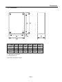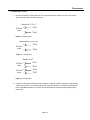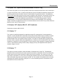
1
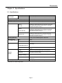
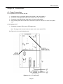
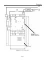
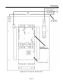
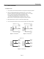
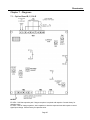
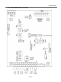
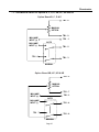
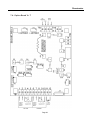
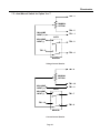
PHASETRONI CS TM SCRPowerCont r olSpeci al i st s 1 P 1 S e r i e s 2 0t o6 0 0A mpMo d e l s S i n g l eP h a s eS C R OPERATI ONANDSERVI CEMANUAL MANUAL-1P120600REV2 REV06/ 1 3/ 1 3 Phasetronics Table of Contents Chapter 1 - Introduction .................................................................................................................................. 4 1.1 General ............................................................................................................................................... 4 1.2 Receiving and Unpacking .................................................................................................................. 4 Chapter 2 - Specifications ............................................................................................................................... 5 2.1 Specification ....................................................................................................................................... 5 2.2 Dimensions ......................................................................................................................................... 6 2.3 Protective Networks ........................................................................................................................... 7 2.4 Ambient Temperature ........................................................................................................................ 7 2.5 Cooling ............................................................................................................................................... 7 Chapter 3 - Installation .................................................................................................................................... 8 3.1 Location .............................................................................................................................................. 8 3.2 Initial Unt Inspection ........................................................................................................................... 8 3.3 Mounting and Cleaning ...................................................................................................................... 9 3.4 Enclosure Ventilation ......................................................................................................................... 9 Chapter 4 - Connections ................................................................................................................................ 10 4.1 Power Connections .......................................................................................................................... 10 4.2 Control Connections ......................................................................................................................... 13 Chapter 5 - Options ........................................................................................................................................ 15 5.1 Option “B” (Standard on all 1P1 units) ............................................................................................. 15 5.2 Option "C" (Option B with the addition of Current Limit) .................................................................. 15 5.3 Option “D” (Option B with the addition of Current Trip) .................................................................... 15 5.4 Option “E” (Option B, C + D Combined) ........................................................................................... 15 5.5 Option “KB” ....................................................................................................................................... 16 5.6 K Series Option Soft Start ................................................................................................................ 16 5.7 K Series Voltage and Current Feedback Signals (Efb and Ifb) ........................................................ 16 5.8 Option “KC”: (Option KB with the addition of Current Limit .............................................................. 16 5.9 Option “KD” (Option KB with the addition of Current Trip) ............................................................... 17 5.10 Option “KE” (Option KB, KC + KD Combined) ................................................................................. 17 5.11 Option “V” ......................................................................................................................................... 17 5.12 Option “T” ......................................................................................................................................... 17 Chapter 6 - Start-Up ....................................................................................................................................... 18 6.1 Manual Control (Options “B” and “KB”) ............................................................................................ 18 6.2 Automatic Control (Options (Options “B” and “KB”) ......................................................................... 19 6.3 Current Limit (Option “C” or “KC”) Start-up ...................................................................................... 19 6.4 Current Trip (Option “E”) Start-up ..................................................................................................... 20 6.5 Current Trip (Option “KE”) Start-up .................................................................................................. 20 6.6 Soft Start (Option “B-E” and “KB-KE”).............................................................................................. 21 6.7 DC Voltage and Current Regulator (Option “V” or “T”) .................................................................... 22 Chapter 7 - Diagrams ..................................................................................................................................... 25 7.1 Option Board B, C, D & E ................................................................................................................ 25 7.2 Option Board KB, KC, KD & KE ...................................................................................................... 27 7.3 Auto/Manual Switch for Options B, C, D, E, KB, KC, KD and KE ................................................ 26 7.4 Option Board V + T ......................................................................................................................... 28 7.5 Auto/Manual Switch for Option V or T .............................................................................................. 29 Page 2 Phasetronics Chapter 8 - Troubleshooting ......................................................................................................................... 30 8.1 SCR Testing Procedure ................................................................................................................... 30 8.2 Replacing Printed Circuit Boards ..................................................................................................... 31 8.3 Replacing SCR Devices ................................................................................................................... 32 8.4 Bench Calibration Procedure ........................................................................................................... 32 WARRANTY INFORMATION .......................................................................................................................... 35 Page 3 Phasetronics Chapter 1 - Introduction 1.1 General The 1P1 series of power controls is a single phase controller available in 120 thru 575vac and with current ratings from 20 to 600A. It provides smooth, phase angle control of back to back SCRs for 0100% output power control. It comes standard with an optically isolated 4-20ma signal input, a manual potentiometer input and Load Voltage Regulation. The integral offset and gain adjustments allow tailoring of the output power with respect to the control signal input. Optional features such as Current Limit and Current Trip are also available. The SCRs are protected by MOVs (Metal Oxide Varistor) and a dv/dt network as standard. The 1P1 series is well suited for a variety of loads including inductive, resistive and high inrush. 1.2 – Receiving and unpacking Upon receipt of this product you should immediately do the following: • Inspect the unit for possible shipping damage (if damaged, you should notify the freight carrier and file a claim immediately) • Verify the model number on the unit matches your purchase order Warning DO NOT SERVICE EQUIPMENT WITH VOLTAGE APPLIED! Unit can be a source of fatal electrical shocks! To avoid shock hazard, disconnect all power sources before working on unit. Page 4 Phasetronics Chapter 2 - Specifications 2.1 - Specifications External Inputs Milliamp Input 4-20 mA Input Impedance - 510 ohms. Manual Control 10k ohm, 2 watt potentiometer, linear taper (customer provided). Output Current Rating (Model dependent) 20 to 600 Amps. AC Supply Voltage 120/208/240/380/415/480/575 Vac(+10% to -15%, 50/60 Hz) * Type of Loads Resistive / Inductive / Lamp. Soft Start: Options B, C, D, E: Options KB, KC, KD & KE: Options V & T: Set for initial half-second of operation at power on. Field adjustable by potentiometer from 0.5 seconds to 25 seconds. Ramp with DC signal change is factory set for 0.1 seconds (adjustable with capacitor change.) Set for initial half-second of operation at power on. Field adjustable by potentiometer from 1 second to 50 seconds. Ramp with DC signal change is factory set for 0.1 seconds (adjustable with capacitor change.) A combination of a high-potential gate pulse and a rapid rise time is used to prevent SCR damage due to di/dt stress. Hard Firing Gate Pulse Input Adjustments Set for initial half-second of operation at power on. Field adjustable by potentiometer from 0.25 seconds to 60 seconds. Ramp with DC signal change is factory set for 0.1 seconds (adjustable with capacitor change.) Gain 4-20mA Offset 50% of gain maximum Option: Load voltage regulation of +/-2% over a +/-10 % line voltage input change. (B,C,D,E,KB,KC,KD & KE) Regulation B,C,D,E,KB,KC,KD & KE Protective Networks Option V & T Specific to DC voltage applications, current and/or Voltage regulation is 0.75%. Fusing Integral I²T fuse protects against short-circuit overloads. Transient Voltage Suppressor Integral MOV (Metal Oxide Varistor) protects against high potential transient voltage. SCR Peak Inverse Voltage (PIV Rating) 1500V RC Snubber RC snubber network prevents false firing due to dv/dt characteristics Ambient Temperature Operating range is from 0°C thru 40°C (32°F thru 104°F) * Dependent on model configuration Page 5 Phasetronics 2.2 - Dimensions A H E B D W 20-40 H (inch.) 10.5 W (Inch.) 6.50 D (Inch.) 4.50 E (Inch.) 0.3125 A (Inch.) 9.875 B (Inch.) 5.875 75 10.5 6.50 6.00 0.3125 9.875 5.875 110-225 13.0 8.50 9.75 2.25 8.50 7.125 300-600 21.0 11.0 10.5 0.3125 19.25 9.25 1P1 AMPS C = Mounting Hole Diameter D = Depth of the unit Dimensions are subject to change Page 6 Phasetronics 2.3 - Protective Networks Transient Voltage Suppressor (Standard): Integral MOV (Metal Oxide Varistor) protects against high potential voltage spikes. RC Snubber (Standard): RC Snubber networks are used to prevent false firing due to dv/dt characteristics. SCR Peak Inverse Voltage (PIV Rating) for line voltage 120 ~ 575V: 1500V for all models. 2.4 - Ambient Temperature Ambient temperature operating range: 0 to 40 °C (32 to 104 °F). Transportation and storage range: 0 to 65 °C (-30 to 149 °F). Note: Output current rating decreases by 10% for each 5 °C rise (9 °F) in ambient temperature over 40 °C (104 °F) to a maximum of 60 °C (140 ° F). 2.5 - Cooling Units rated 20 to 225 Amps are convection cooled. Units rated 300 Amps and above are fan cooled. Page 7 Phasetronics Chapter 3 - Installation 3.1 - Location Proper location of the 1P1 Series is necessary to achieve specified performance and normal operation lifetime. The 1P1 Series should always be installed in an area where the following conditions exist: • Ambient operating temperature: • • • • • 0 to 40 degrees C (32 to 104 degrees F) - Type 1 ventilated enclosure Protected from rain and moisture Humidity: 5 to 95% non-condensing Free from metallic particles, conductive dust and corrosive gas Free from excessive vibration (below 0.5G) Open panel units must be mounted in the appropriate type of enclosure. Enclosure size and type must be suitable to dissipate heat generated by the SCR power control. (NEMA 1 style enclosures can be forced ventilated to reduce size.) Use the following formulas for sizing non-ventilated enclosures: Non-vented painted metal enclosures: (FLA x7 1.5 ) = sq. ft of exposed area Non-vented stainless steel enclosures: (FLA x4 1.5 ) = sq. ft of exposed area Mount units vertically so heat sink fins are parallel to vertical mounting surface. Non Fan cooled units must be mounted with the power terminals located at the bottom to ensure proper cooling. Notes: - FLA is the 1P1 unit current rating. The area of the enclosure that is against the wall when mounted is not included in the "Exposed" area for cooling considerations. 3.2 - Initial Unit Inspection Prior to installing the 1P1 Series unit make a complete visual check of all the equipment for possible damage in shipping and handling. Report damage immediately before attempting to run unit. Check for loose mechanical assemblies or broken wires which may have occurred during transportation or installation. Loose electrical connections will increase resistance and cause the unit to function improperly. Prior to beginning the installation verify the 1P1 Series unit is rated for the proper voltage and current for the load. Warning Do not service equipment with voltage applied! Unit can be source of fatal electrical shocks! To avoid shock hazard, remove all sources of power before working on controller. Warning labels must be attached to terminals, enclosure and control panel to meet local codes. Page 8 Phasetronics 3.3 - Mounting and Cleaning If mounting the 1P1 Series unit in an enclosure requires drilling or punching holes in the enclosure, cover the electrical assembly to prevent metal filings from becoming lodged in areas which can cause clearance reduction or actually short out electronics. After work is complete, thoroughly clean the area and re-inspect the 1P1 Series unit for foreign material. Make sure to observe the required wire bending space per NEC, NFPA and local codes when installing the unit. To maximize effective air flow and cooling, the unit must be installed with its heat sink ribs oriented vertically and running parallel to the mounting surface. If the unit has a fan, install unit so the fan blows upward vertically. In dirty or contaminated atmospheres the unit should be cleaned on a regular basis to insure proper cooling. Do not use any chemicals to clean the unit. To remove surface dust, use 80 to 100 psi clean dry compressed air only. A three inch high quality dry paint brush is helpful to loosen the dust prior to using compressed air on the unit. WARNING! Remove all sources of power before cleaning the unit. 3.4 – Enclosure Ventilation 75, 110 and 225 Amp units require a 120 cfm box ventilation fan for NEMA 1 enclosures. 300 Amp and larger units require a 240 cfm vent fan. See example below. Figure 1 - Enclosure Note: Any box size should be selected in coordination with minimum field wiring bending space requirements per local and National Electrical Codes. Page 9 Phasetronics Chapter 4 - Connections 4.1 - Power Connections 4.1.1 - Options B, C, D, E, KB, KC, KD, KE 1. 2. 3. 4. Connect the Line 1 input power cables to the terminal on the unit marked L1. Connect the Load input power cable to the terminal on the unit marked T1. Connect the Load output power cable and the L2 power cable together. Using a 14awg, 600v wire, fused at 2A, connect the L2 power to TB2 pin 7 on the 1P1 unit option card. 4.1.2 - Options V & T 1. Connect the L2 lead to TB4-4 on the PTR trigger card. Note: The trigger card is located under the option card in units rated 20-75A. See Fig 2a to 2c for overall wiring schemes. Figure 2a: 20, 40, 75 AMP UNITS Page 10 Phasetronics Figure 2b: 110, 140, 175 AMP UNITS Page 11 Phasetronics Figure 2c: 225, 300, 400, 500, 600 AMP UNITS Page 12 Phasetronics 4.2 - Control Connections 4.2.1 Manual Control 1. The connection of the manual potentiometer is not required for automatic operation. 2. For B, C, D & E the potentiometer is connected to TB1 -3, -6 & -9. (Fig 3) For KB, KC, KD & KE the potentiometer is connected to TB1-5, -6 & -7. (Fig 4) For V or T there are two manual control potentiometers. (Fig 5) The Voltage control potentiometer is connected to TB1-3, -4 & -5. . The Current Control potentiometer is connected to TB1-8, -9 & -10. Refer to Section 7 for specific option card type and connection locations. 3. Manual potentiometer is 10K ohm, 2 watts linear resistance taper. 4. If you are using only manual pot control, proceed to chapter 5 & 6 Start-up details. Options B, C, D + E Inc 10K Ohm 2 Watt Linear Taper Options KB, KC, KD + KE TB1-6 (High) Inc TB1-3 (Wiper) TB1-9 (Low) 10K Ohm 2 Watt Linear Taper Figure 3 – Potentiometer TB1-5 (High) TB1-6 (Wiper) TB1-7 (Low) Figure 4 – Potentiometer Option V or T Inc 10K Ohm 2 Watt Linear Taper TB1-3 (High) TB1-4 (Wiper) TB1-5 Voltage section (Low) Inc 10K Ohm 2 Watt Linear Taper TB1-9 (Wiper) TB1-10 Current section (Low) Figure 5 – Potentiometer Page 13 TB1-8 (High) Phasetronics 4.2.2 Automatic Control 1. Connect the milliamp control signal to TB1 on the option board. Refer to section 7 for specific option card type and connection locations. Options B, C, D + E 4-20 mA Input + TB2-1 - TB2-2 Figure 6 – Analog Input Options KB, KC, KD + KE 4-20 mA Input + TB1-3 - TB1-4 Figure 7 – Analog Input Options V or T 4-20 mA + Input - TB1-1 4-20 mA + Input - TB1-6 TB1-2 TB1-7 Figure 8 – Analog Input 2. If both the manual and automatic control signals are needed, consider installing an auto/manual switch. (See section 7) If both the manual and automatic signals are connected simultaneously and an Auto/Manual switch is not used, the unit will follow the command signal with the larger input value. Page 14 Phasetronics Chapter 5 – Control Options 5.1 Option "B" (Standard on all 1P1 units) Both, the 4-20 milliamp and Manual Potentiometer control signal inputs are standard. The Offset (R12) & Gain (R15) adjustments allow for tailoring of the 4-20ma signal to scale the output voltage to most applications. When a Manual Potentiometer is used in conjunction with the Automatic signal, an Auto/Manual switch for selectable Local/Automatic operation should be added. (See section 7). The standard Power On soft start is adjustable from 0.25 seconds when fully clockwise to 60 seconds when set fully counter clockwise. The integral Load Voltage Regulation feature provides a means of stabilizing the output voltage when input voltage variations are present .The output voltage is monitored thru the onboard feedback transformer and the control loop compares it to the command signal to provide regulation. Output regulation of +/-2% over a +/-10% input voltage swing can be beneficial in heating or other critical applications where stability and repeatability is of concern. This feature is factory calibrated. Adjusting the Feedback potentiometer will cause the units regulation to be affected and should be avoided. 5.2 Option "C" (Option B with the addition of Current Limit) Provides an additional layer of protection for dynamic and non-linear loads. Adjustable from 0-125% of the units rating, this option will override the control signal to limit the output current to a preset level. By adjusting the Current Limit pot (R63) on the option card, the level can be set to zero at the fully counter clockwise position to 125% of the units rating when at the fully clockwise position. This feature is useful when the load can vary during process transitions or during a start-up condition. This option can also be disabled by removing the "X2" jumper on the option card if necessary. 5.3 Option “D” (Option B with the addition of Current Trip) The Current Trip option is over current protection that when activated will shut off the units current flow in 1/2 cycle of line power or less. It's peak current detector circuitry will initiate the shutdown sequence the instant any peak current exceeds the Current Trip threshold set by potentiometer R42. The adjustment range is 75% to 200% of unit rated current. The Sensitivity to a trip (lower threshold) is increased as the adjustment is turned clockwise. Minimum Sensitivity is when the adjustment is turned fully counter clockwise. Current Trip is a latched trip and requires a momentary manual reset via a normally open dry contact connected to TB1-4 and TB1-7 or TB1-8. (See section 7). 5.4 Option “E” (Options B, C + D Combined) Combination of options B, C and D. Page 15 Phasetronics 5.5 Option “KB” Both, the 4-20 milliamp and Manual Potentiometer control signal inputs are standard. The Offset (P1) & Gain (P2) adjustments allow for tailoring of the 4-20ma signal to scale the output voltage to most applications. When a Manual Potentiometer is used in conjunction with the Automatic signal, an Auto/Manual switch for selectable Local/Automatic operation should be added. (See section 7). The standard Power On Soft Start is adjustable from 0.5 seconds when fully counter clockwise to 25 seconds when set fully counter clockwise. The integral Load Voltage Regulation feature provides a means of stabilizing the output voltage when input voltage variations are present .The output voltage is monitored thru the onboard feedback transformer and the control loop compares it to the command signal to provide regulation. Output regulation of +/-2% over a +/-10% input voltage swing can be beneficial in heating or other critical applications where stability and repeatability is of concern. This feature is factory calibrated. Adjusting the Feedback potentiometer will cause the units regulation to be affected and should be avoided. 5.6 K Series Option, Soft Start This feature is standard on all K options and is slightly different than the standard "B" series option. It provides a soft start at Power Up, on a Current Trip Reset (If using Option KD or KE) or when Lockout is released. It protects fuses from inrush currents and is well suited for high inrush loads and delicate heater elements. The ramp rate is adjusted by the P5 potentiometer on the option card. When set at minimum (fully counter clockwise) the ramp time is ~0.5 seconds to 100% output. When set at Max (fully clockwise) the ramp time is ~24 seconds. This option can also be disabled by removing the "X3" jumper on the option card, see section 7 for the jumper location. 5.7 K Series Voltage and Current Feedback Signals (Efb and Ifb) All K series option cards come with two 0-10vdc output signals that represent the 0 to100% output current and voltage of the unit. Both signals are low impedance output (470 ohms) and can drive up to 2ma. The Ifb signal is available between pins 8 & 9 on TB1, where pin 9 is the common and pin 8 is the 0-10vdc output. The Efb signal is available between pins 9 & 10 on TB1 with 9 being the common and 10 as the output. Both feedback signals are factory calibrated. Fine tuning for a specific application or scale is available by potentiometers P4 for the Efb and P9 for the Ifb. A clockwise turn will increase the output and a counterclockwise adjustment will decrease the output. 5.8 Option “KC” (Option KB with the addition of Current Limit) Provides an additional layer of protection for dynamic and non-linear loads. Adjustable from 0-125% of the units rating, this option will override the control signal to limit the output current to a preset level. By adjusting the Current Limit pot P8 on the option card, the level can be set to zero at the fully counter clockwise position or up to 125% of the units rating when at the fully clockwise position. This feature is useful when the load can vary during process transitions or during a start-up condition. This option can also be disabled by removing the "X4" jumper on the option card if necessary. Page 16 Phasetronics 5.9 Option “KD” (Option KB with the addition of Current Trip) The Current Trip option is over current protection that when activated will shut off the units current flow in 1/2 cycle of line power or less. Its peak current detector circuitry will initiate the shutdown sequence the instant any peak current exceeds the Current Trip threshold set by potentiometer P6. The adjustment range is 75 to 200% when going from fully counter clockwise to fully clockwise. The K series Current Trip is not latching and is automatically reset after an adjustable time has expired. The Trip Reset time is configured by two jumpers and adjusted by potentiometer, P7. The Short Range jumper X1 allows adjustment from 1 to 12 seconds of delay before an automatic reset is attempted. The Long Range Jumper X2 allows for adjustment from 10 to 21 seconds. Minimum time is with P7 fully counter clockwise. Maximum time is with P7 fully clockwise. 5.10 Option “KE” (Options KB, KC + KD Combined) Combination of options KB, KC & KD. 5.11 Option “V” The V option is specifically designed for applications where DC voltage and/or Current regulation is required. It comes standard with a manual pot and optically isolated 4-20ma input for both the Constant Voltage and Constant Current commands. Its automatic crossover feature is standard and allows for smooth transition from one regulation mode to another. The power on soft start feature prevents inrush into filter circuits or dynamic loads and is adjustable from a minimum of 0.5 seconds with P7 fully counter clockwise to a maximum of 25 seconds with P7 set fully clockwise. With regulation of typically better than 0.75%, it is well suited for plating rectifier, battery charging and any other application that requires a constant voltage or current. 5.12 Option “T” This option is the same as Option V with the addition of instantaneous Current Trip. This additional protection feature monitors the peak output current and provides an adjustable Current Trip setting (P6) of 50% when set fully counter clockwise to 200% when set fully clockwise. If a current trip occurs, the units output is shut down in 1/2 line cycle or less and the onboard current trip relay contacts located at TB4 are activated along with the red Current trip LED. The Trip condition is now latched until a normally closed trip reset contact connected to TB1 pins 11 & 12 is momentarily opened. This allows the unit to soft start back to the command value. Page 17 Phasetronics Chapter 6 - Start-up WARNING! High Voltage present qualified personal only. Equipment Required: Digital Volt Meter Clamp on Current Meter Appropriately Rated Personal Protection Equipment Non-metallic small flat blade screwdriver 6.1 Manual Control (Options “B” + “KB”) The following procedure is used for manual control start-up of the 1P1 Series Control. 1. If the unit has an automatic control signal connected, set it to zero or disconnect it. 2. If the unit has current limit or current trip options, consider setting their adjustment potentiometers (R45 & R63 or P6 & P8 for K series) to their maximum settings to ensure they do not interfere with the start up. 3. Set the digital meter to resistance and verify the manual pot is at minimum by ohming between terminals TB1-3 and -9 for the standard option and TB1-6 & -7 for the K series option. It should read less than 1 ohm. If not verify the potentiometer connections before proceeding. 4. Place the Clamp on current meter over the cables connected to the T1 (Load) terminal on the unit. 5. Set the digital volt meter to AC volts and connect it to the T1 output terminal and the L2 connection on the option card. 6. Energize the main power and verify there is no current or voltage output. 7. Slowly rotate the manual pot clockwise while monitoring the voltage and current. The units output should begin to gradually rise as the manual pot is turned. 8. Continue to turn the manual pot until it is at maximum. 9. Verify the units output voltage is at maximum and the current reading is as expected. 10. Slowly reduce the manual pot to zero and verify the units output followed. 11. Remove the units power and disconnect the current and volt meters. 12. The unit is now ready to put into service. Note: If the unit is connected for manual control only and optional current limit is provided, proceed to current limit start-up procedure (Section 6.3). If operating under manual control only, you have completed start-up. Page 18 Phasetronics 6.2 Automatic Control (Options “B” and “KB”) The following procedure is used for automatic control start-up of the 1P1 Series Control. 1. Offset and Gain adjustments for the 4-20ma Automatic signal are factory calibrated. 2. If the unit has current limit or current trip options, consider setting their adjustment potentiometers (R45 & R63 or P6 & P8 for K series) to their maximum settings to ensure they do not interfere with the start up. 3. Place the current meter around the T1 output lead from the unit. 4. Set the digital volt meter to AC volts and connect it to the T1 output terminal and the L2 connection on the option card. 5. Energize the unit and verify there is no output voltage or current. 6. Increase the automatic signal gradually to 100% (Max) and verify the units output voltage increases as well and follows the command signal level. 7. Verify the units output voltage is at maximum and the current reading is as expected. 8. Slowly reduce the automatic signal to minimum and verify the unit output followed. 9. Remove the units power and disconnect the current and volt meters. 10. The unit is now ready to put into service. 6.3 Current Limit (Option “C” + “KC”) Start-up 1. This section assumes the regular start up in sections 6.1 and/or 6.2 have been successfully completed and the current/volt meters are still connected. 2. Verify the current limit potentiometers R63 or P8 (K series) are set to maximum. 3. Energize the unit. 4. Increase the manual pot or automatic control signal to maximum. 5. Verify the units output is at maximum. 6. Monitor the Voltage and Current meters and slowly decrease the current limit pot setting until the units output begins to decrease. 7. Continue to decrease the current limit adjustment counter clockwise until the desired current limit point is reached. This will set a maximum current limit value. 8. If the unit is required to output full voltage, slowly increase the current limit pot until the units output voltage reaches maximum again. This will set the current limit point just above the full voltage output value. 9. Adjust the command signal to minimum, then maximum and down to minimum again. 10. Verify the current limit value is correct and the unit performs as needed. Page 19 Phasetronics 6.4 Current Trip (Option "E") Start-up 1. This section assumes the regular start up in sections 6.1 and/or 6.2 have been successfully completed and the current/volt meters are still connected. 2. Verify the Current Trip potentiometer R42 is set fully counter clockwise. (Minimum Sensitivity) 3. Energize the unit 4. Increase the manual or automatic control signal to maximum. 5. Verify the units output is a maximum. 6. Monitor the Voltage and Current meters and slowly turn the Current Trip pot R42 clockwise (increase sensitivity) until the units output abruptly drops to zero. 7. Momentarily press the Trip Reset button connected between TB1-4 and -8. 8. The unit should switch on. If the unit fails to come on, adjust the Current Trip pot R42 slightly counter clockwise to decrease the sensitivity and momentarily press the reset button again. 9. Repeat this process until the unit will remain on after a reset. 6.5 Current Trip (Option “KE”) Start-up 1. This section assumes the regular start up in sections 6.1 and/or 6.2 have been successfully completed and the current/volt meters are still connected. 2. Verify the Current Trip potentiometer P6 is set fully clockwise (Maximum) 3. Select either the Long or Short, Current Trip Reset Time range jumper X1 or X2 (See section 7). 4. Set the Current Trip Reset Time potentiometer P7 to mid-scale. 5. Energize the unit. 6. Increase the manual pot or automatic control signals to maximum. 7. Verify the units output is at maximum. 8. Monitor the Voltage and Current meters and slowly turn the Current Trip Pot (P6) counter clockwise (decrease) until the units output abruptly drops to zero. 9. Allow the Auto Reset Time to expire while monitoring the output voltage. 10. At the end of the Auto Reset Time the unit will ramp the output voltage to the command level. 11. The unit may trip again during the ramp up. If this occurs increase the Current Trip adjustment a small amount and allow the Auto Reset Timer to cycle again. 12. Repeat this process until the unit can ramp to 100% power without a Current Trip. 13. Decrease the command signal to minimum. 14. Increase the command signal again to maximum. If the unit trips again, increase the Current Trip adjustment slightly and repeat the Reset process until the unit can reach full output. Page 20 Phasetronics 6.6 Soft Start (Option “B-E” and “KB-KE”) This section assumes the regular start up in sections 6.1 and/or 6.2 have been successfully completed and the current/volt meters are still connected. 6.6.1 Options B-E 1. Option B thru E soft start is active only during power up. 2. Preset the Soft start potentiometer R46 to mid scale. 3. Remove power from the unit and wait one minute. 4. Increase the command signal (Manual or Automatic) to maximum. 5. While monitoring the volt meter, apply power to the unit and time how long it takes the unit to reach maximum output. 6. Adjust R46 counter clockwise to decrease the soft start time or clockwise to increase the soft start time. 7. Repeat steps 2 thru 5 until the desired soft start time is reached. 6.6.2 Options KB thru KE 1. Preset the Soft Start potentiometer P5 on the option card to mid-way. 2. Connect a normally open, dry, contact to TB1 pins 1 & 2. 3. Increase the command signal (Manual or Automatic) to maximum. 4. While monitoring the volt meter, apply power to the unit and time how long it takes the unit to reach maximum output. 5. Close the contact at TB1 pins 1 & 2 and verify the unit output drops to zero. 6. Open the contact at TB1 pins 1 & 2 and verify the unit output again ramps to maximum output. 7. Adjust the Soft Start pot P5 clockwise to increase ramp time (slower) or counter clockwise to decrease ramp time (faster) as needed. 8. Repeat steps 5 - 7 until the soft start is set to the desired time. Page 21 Phasetronics 6.7 DC Voltage and Current Regulator (Option “V” and “T”) Due to the multitude of applications and DC voltages any given system can be designed for and to maintain 100% flexibility with any system the V and/or T options are not configured for immediate use when shipped on AC output units such as the 1P1 series. The V/T option series must be configured for the end use application before a startup sequence can be attempted. 6.7.1 V and T Option Setup 1. The V & T options are used with DC voltage systems and require feedback signals from the voltage and/or current to operate correctly. 2. The Current feedback signal is from a 50millivolt shunt that is located in the negative leg of the DC output circuit. For proper performance the shunt must be connected directly to the negative output of the rectifier before any filter components. Fig 9 shows typical connections. The shunt signals are then brought back to TB2 pins 3 & 4 on the V/T option card with pin 3 being the positive side of the shunt and pin 4 being the negative. 3. A DC Voltage feedback signal is also required from the positive output of the rectifier. A single lead wire that is appropriately rated and fused is connected to the rectifiers positive output prior to any filtering components and is brought back to TB2 pin 1 on the V/T option card as the DC voltage feedback signal. Fig 9. Shows typical connections. Figure 9 Page 22 Phasetronics 6.7.2 V and T Option Configuration & Connections. 1. Determine the Feedback Resistor using the following equation; where is the feedback resistor value and is the maximum DC output voltage. 2. Solder the feedback resistor to turrets E5 & E6. 3. Select and install the remaining pad components. Note: All caps are 35Vdc minimum. Voltage section, E7 & E8 = 15uf, Electrolytic or Tantalum, E9 & E10 = 0.47uf, Paper, Film or Ceramic. Current section, E11 & E12 = 0.47uf, Paper Film or Ceramic. E13 & E14, 0.22uf, Paper, Film or Ceramic. 4. 4-20ma connections; (if Milliamp signals are not used skip to item 5.) Connect the Voltage control signal to TB1 pins 1 & 2 with 1=positive and 2 = negative Connect the Current control signal to TB1 pins 6 & 7 with 6=positive and 7=negative See section 7 for connection illustration 5. Connect the Voltage control pot to TB1 pins 3(low), 4(wiper) & 5(high) Connect the Current control pot to TB1 pins 8(low), 9(wiper) & 10(high) See section 7 for connection illustration Note: If only one control mode is used, the other must be fully enabled by placing a jumper or closed contact from the wiper position to the high side position. i.e. from TB1-4 to TB1-5 for example. See section 7 for connection illustration 6. Connect the Positive Feedback voltage from the rectifier output to TB2 pin 1. 7. Connect the Negative side of the shunt to TB2-4. 8. Connect the positive side of the shunt to TB2-3. Note: If the shunt is not used a jumper must be placed between TB2-3 and -4. 9. The "T" option provides a Form C fault contact located at TB4. Pin 1 = Common, Pin 2 = Normally Open and Pin 3 = Normally Closed. The Contacts are rated 120vac @ 0.5A and change state upon a current trip signal. They revert back after the trip reset signal has been received. 10. For Option T, connect a normally closed Trip reset contact between TB1-11 and -12 (Momentary open to reset). 11. Both the V and T options provide a 0-6vdc output control signal at TB3 that is designed to interface with the legacy Vectrol firing cards and the PTR6009 series of SCR firing cards. Pin 1 is the output signal and pin 2 is signal common. 12. In applications where both Local and Remote control signals are utilized, an Auto/Manual switch should be installed to isolate the unused or unwanted input signal. See section 7 for typical connections. Page 23 Phasetronics 6.7.3 Option V and T Startup. 1. Before applying power, set all potentiometer adjustments as follows. Voltage Adjust Pot, Fully Counter Clockwise. (4-20ma at minumum) Current Adjust Pot, Fully Clockwise. (4-20ma at maximum) Voltage Feedback Trim Pot P5, Fully Counter Clockwise. Current Trip Pot (option T only) P6 fully Clockwise. Soft Start Pot P7, mid range. 2. Apply power and adjust the Voltage control pot or 4-20ma signal to maximum. 3. Adjust the Voltage Feedbcak Pot P5 slowly clockwise until the output voltage level reaches maximum. 4. Reduce the manual pot or automatic signal slightly and verify the units output follows. If not, increase the signal to maximum and readjust the P5 pot. 5. If Voltage control is responding correctly, set it to maximum and slowly decreae the Current control signal to verify the output from the system follows the control signal. Note: If the load is significantly smaller than the shunt value, the current control pot/signal will appear to have no effect until the low end is reached. This is due to the very small feedback signal from the shunt. To properly verify the current control mode, the full rated load should be used. 6. For option T, the system must have a full load applied to correctly adjust this feature. 7. With the system under full load and at maximum output, slowly decrease the Current Trip pot P6 by turning it counter clockwise until the units output abruptly drops to zero. 8. Verify the Red Current Trip LED is on and the relay contacats at TB4 have changed state. 9. Momentarilly press the trip reset button and verify the unit comes back on and ramps up. 10. If the unit trips again as the output ramps up, increase the P6 Trip setting slightly and reset again. 11. Increasing the soft start time by adjusting P7 clockwise will also help prevent the inrush and help prevent the unit from tripping on a reset. Page 24 Phasetronics Chapter 7 - Diagrams 7.1 – Option Board B, C, D & E NOTES: E5 & E6 – Soft Start capacitor pad. If longer ramp time is required add capacitor. Consult factory for capacitor value. E1 & E2 – Rate of change capacitor. Add a capacitor to slow the response time with respect to control signal input change. Consult factory for capacitor value. Page 25 Phasetronics 7.2 - Option Board KB, KC, KD & KE Page 26 Phasetronics 7.3 - Auto/Manual Switch for Options B, C, D, E, KB, KC, KD and KE Option Board B, C, D & E TB1 - 6 MANUAL OPTION TB1 - 9 MILLIAMP INPUT (+) TB1 - 1 AUTO MILLIAMP INPUT (-) TB1 - 2 TB1 - 9 TB1 - 3 MANUAL Option Board KB, KC, KD & KE TB1 - 5 MANUAL OPTION TB1 - 7 MILLIAMP INPUT (+) TB1 - 3 AUTO MILLIAMP INPUT (-) TB1 - 4 TB1 - 7 TB1 - 6 MANUAL Page 27 Phasetronics 7.4 - Option Board V + T Page 28 Phasetronics 7.5 –Auto/Manual Switch for Option V or T TB1 - 3 MANUAL OPTION TB1 - 5 MILLIAMP INPUT (+) TB1 - 1 AUTO MILLIAMP INPUT (-) TB1 - 2 TB1 - 5 TB1 - 4 MANUAL Voltage Control Section TB1 - 8 MANUAL OPTION TB1 - 10 MILLIAMP INPUT (+) TB1 - 6 AUTO MILLIAMP INPUT (-) TB1 - 7 TB1 - 10 TB1 - 9 MANUAL Current Control Section Page 29 Phasetronics Chapter 8 - Troubleshooting 8.1-SCR Testing Procedure Remove all power sources from the unit! Disconnect load and line leads. Observe all lock out / tag out practices. Equipment required: Medium to large flat blade screwdriver Digital Volt / Ohm meter Hex Key Set 8.1.1 Anode to Cathode Measurements Remove line power from the unit and lock out. Disconnect the load and line leads. The testing procedure for SCRs is comprised of two separate tests. The first procedure tests the anode to cathode integrity of the SCR by performing the following ohm checks: + Lead - Lead Good Consult Factory L1 Lug T1 Lug Greater than 10k ohm Less than 10k ohm 8.1.2 Gate to Cathode Measurements Note the type of color coding of the wires going to the SCR plug. Phasetronics uses two configurations. The first is made up of four wires color coded Black, Yellow, Gray and White. The second is color coded Red, White, Red White. Ohm the Black & Yellow pair of wires, then ohm the Gray and White pair of wires. Compare your readings to the information in Fig 10 below. For units with two sets of Red/White wires, ohm each set of Red/White wires and compare your readings to Fig 10 below. For wire that is color coded black, yellow, gray and white + Lead - Lead Good Bad Black Yellow Between 5 and 32 ohm Less than 5 or greater than 32 ohm Gray White Between 5 and 32 ohm Less than 5 or greater than 32 ohm For wire that is color coded red, white, red and white + Lead - Lead Good Bad Red White Between 5 and 32 ohm Less than 5 or greater than 32 ohm Red White Between 5 and 32 ohm Less than 5 or greater than 32 ohm Figure 10 Note: If any of the above readings are out of specification, replace the faulty SCR. Page 30 Phasetronics 8.2 - Replacing Printed Circuit Boards The printed circuit boards are not intended to be field repaired. If a board is found to be faulty, the entire board should be replaced. Important! Use ESD Precautions any time you replace circuit boards. 1. Remove all power and lock out 2. Option Card replacement. 2.1. Disconnect the Red plug on J1. 2.2. Note and mark the locations of all potentiometers. 2.3. Label all wires to each Terminal block being used. 2.4. Disconnect all wires connected to the option card. 2.5. Using a Phillips screwdriver, remove the four mounting screws. 2.6. Remove the defective option card. 2.7. Install the new option card 2.8. Install the 4 mounting screws and tighten lightly. 2.9. Reconnect the tagged wire to their respective terminal block locations. 2.10. Preset all potentiometers the same as the previous option card. 2.11. Reconnect the Red plug on J1. 2.12. Go thru Start up procedures in section 6. 3. Trigger Card Replacement for 20-75A units. 3.1. Remove all power and lockout. 3.2. Remove option card using steps 2.1 thru 2.6. 3.3. Disconnect both red plugs connected to the trigger board. 3.4. Disconnect the wires at TB4. 3.5. Remove the four standoffs that mount the trigger card. 3.6. Remove the defective trigger card. 3.7. Install the new trigger board. 3.8. Reinstall the wires at TB4. 3.9. Install the four standoffs that mount the trigger board. 3.10. Reconnect all red plugs previously disconnected. 3.11. Install the option card using steps 2.7 thru 2.12. 3.12. Go thru Start up procedures in section 6. 4. Trigger Card replacement for 110 thru 600A units. 4.1. Remove all power and lockout. 4.2. Disconnect all red connectors. 4.3. Tag and remove any other wires connected to the trigger card. 4.4. Using a Philips Screwdriver, remove the four PCB mounting screws. 4.5. Remove the old trigger board assembly. 4.6. Mount the replacement PCB assembly. 4.7. Re-install the mounting screws. 4.8. Reconnect the red plugs disconnected earlier. 4.9. Reconnect any wires disconnected earlier as part of the removal process. 4.10. Inspect all work and clean area of tools before applying power to test. 4.11. Go thru the startup procedures in section 6. Page 31 Phasetronics 8.3 Replacing SCR Devices The SCRs utilized in the 1P1 series are not field serviceable. If you have determined a failed SCR has occurred, please contact the Phasetronics Return Material Department for a return Material Authorization Request Form or a factory authorized repair center for assistance. 8.4 Bench Calibration Procedure All 1P1 units are factory calibrated for 0 to 100% proportional control. The following procedures can be used to restore the factory alignment if you encounter a situation where all the potentiometers on the 1P1 have been misadjusted due to field calibration attempts and normal control of the unit has been lost. Equipment and Items required: 1: Digital Volt/Ohm Meter 2: Linear Resistance Taper Potentiometer.10K ohm, 2 watt 3: Automatic signal Generator: 4 – 20mA 4: Small Flat Blade Screw Driver. 5: Dummy load capable of the units rated voltage. Example: Use 4pcs 100W, 120v incandescent lamps in series for a 480v unit or 2 in series for a 208240v unit. Lamps are preferred to provide visual confirmation but are not mandatory. Any resistive load that is capable of the unit’s voltage is acceptable. 8.4.1 Basic Calibration Option B 1. 2. 3. 4. 5. 6. 7. 8. 9. 10. 11. 12. 13. 14. 15. 16. 17. 18. 19. 20. Connect the line power and dummy load per section 4.1 Connect the manual potentiometer and Automatic control signal per section 4.2. Verify the manual pot and automatic signal are at minimum. Preset R12 fully counterclockwise. Preset R15 fully counter clockwise. Preset R31 fully counter clockwise. Set the digital volt meter to AC volts and connect it to the T1 and L2 terminals. Energize the unit and verify there is a minimal output voltage from the unit. Adjust "Offset" pot R12 slowly clockwise until the output is offset to basically zero volts. Increase the 10 K Manual Potentiometer to maximum. Adjust the Feedback Pot R31 slowly clockwise to increase the output voltage to max. Adjust R31 slightly counter clockwise to reduce the max output voltage by about 1vac. Slowly decrease the manual pot to min and verify the unit output follows the command. Slowly swing the manual pot from min to max and back to verify the unit follows. Increase the automatic signal (4-20ma) to maximum. Slowly adjust the "Gain" pot R15 clockwise to increase the units output to maximum. Decrease the automatic signal to 90% and verify the output voltage dropped as well. If the output voltage did not decrease, repeat steps 14 thru 16. Decrease the automatic signal to zero (0%) Verify the units output voltage is again at the minimum (Zero) level. Page 32 Phasetronics 21. If needed adjust the offset pot R12 slightly clockwise to "zero" the units output. 22. Monitor the output voltage and verify the automatic signal has correct control by spanning it form minimum to maximum. 23. Adjust the manual pot to maximum. 24. Remove power from the unit and wait 5 seconds. 25. Apply power and verify the soft start is ramping the output voltage. 26. Remove power and adjust R46 as needed for appropriate ramp rate. 27. Repeat steps 24 thru 26 as needed to adjust ramp rate. 28. Reduce all command signals to minimum and remove power from the unit. 29. Disconnect all control signals and metering devices. 30. The basic calibration is now completed. 31. END PROCEDURE. 8.4.2 Calibration with Option KB 1. 2. 3. 4. 5. 6. 7. 8. 9. 10. 11. 12. 13. 14. 15. 16. 17. 18. 19. 20. 21. 22. 23. 24. 25. 26. 27. 28. 29. Connect the line power and dummy load per section 4.1 Connect the manual potentiometer and Automatic control signal per section 4.2. Verify the manual pot and automatic signal are at minimum. Preset option board pots P1 midrange, P2 fully counter clockwise and P3 fully clockwise. Set the digital volt meter to AC volts and connect it to the T1 and L2 terminals. Energize the unit Adjust pot P1 slowly clockwise until the unit has output. Monitor the output voltage and adjust P1 slowly counter clockwise to zero the unit output. Slowly increase the manual pot to max and verify the unit output follows the command. Monitor the output voltage and adjust pot P3 counter clockwise to increase the unit output to maximum. Slowly decrease the manual pot to minimum. Adjust P1 as needed to zero the units output again. Increase the manual pot to max and verify the unit output follows the command. Decrease the manual pot slightly and verify the unit output follows. If not, repeat steps 9 thru 11. Decrease the manual pot to minimum. Increase the automatic signal (4-20ma) to maximum. Slowly Adjust the P2 Gain pot clockwise to increase the units output to maximum. Slowly adjust P2 counter clockwise to reduce the output voltage by about 1vac. Decrease the automatic signal to 90% and verify the output voltage dropped as well. Decrease the automatic signal to zero (0%) Verify the units output voltage is again at the minimum level. If needed adjust the offset pot P1, accordingly to "zero" the units output. Monitor the output voltage and verify the manual pot has correct control by spanning it from minimum to maximum and back to minimum. Monitor the output voltage and verify the automatic signal has correct control by spanning it form minimum to maximum and back to minimum. Adjust the manual pot to maximum. Remove power from the unit and wait 5 seconds. Apply power and verify the soft start is ramping the output voltage. Remove power and adjust P5 clockwise to increase, or counter clockwise to decrease the soft start ramp time as needed. Repeat steps 27 & 28 as needed to dial in the desired Power On Soft Start Time. Page 33 Phasetronics 30. 31. 32. 33. Reduce all command signals to minimum and remove power from the unit. Disconnect all control signals and metering devices. The basic calibration is complete. END PROCEDURE Page 34 Phasetronics Warranty Information Phasetronics warrants its products to be free from defects in material and/or workmanship for a period of one year from date of installation, to a maximum of 18 months from the date of shipment as indicated by the unit’s date code. The Company reserves the right to repair or replace any malfunctioning units under warranty at their option. All warranty repairs must be performed by the Company factory or on site by a factory authorized service firms or personnel approved by the Company. Solid state controls have different operation characteristics from those of electro-mechanical equipment. Because of these differences and the wide variety of applications for solid state controls, each application designer must verify that the solid state equipment is acceptable for his application. In no event will Phasetronics be responsible or liable for indirect or consequential damages resulting from the use or application of this equipment. The diagrams and illustrations in this document are included solely for illustrative purposes. Because of the number of different applications, Phasetronics cannot be responsible or liable for actual use based on the examples or diagrams. Page 35