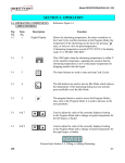
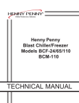
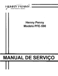
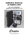
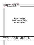
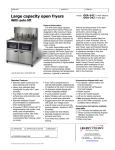
1
Henny Penny Open Fryer Technical Manual Model OFE-141 Model OFE-142 FM06-052-D 08-26-14 This manual and Wiring diagram should be retained in a convenient location for future reference. The Model OFE-14X open fryer cannot be operated without electric power. The unit will automatically return to normal operation when power is restored. Improper installation, adjustment, alteration, service, or maintenance can cause property damage, injury, or death. Read the installation, operating, and maintenance instructions thoroughly before installing or servicing this equipment. DO NOT STORE OR USE GASOLINE OR OTHER FLAMMABLE VAPORS AND LIQUIDS IN THE VICINITY OF THIS OR ANY OTHER APPLIANCE. FIRE OR EXPLOSION COULD RESULT. TABLE OF CONTENTS Section Page Section 1. INTRODUCTION 1-1. Introduction ......................................................................................................... 1 1-2. Features ............................................................................................................. 1 1-3. Proper Care ........................................................................................................ 1 1-4. Assistance .......................................................................................................... 1 1-5. Safety ................................................................................................................. 1 Section 2. INSTALLATION 2-1. Introduction ......................................................................................................... 3 2-2. Unpacking........................................................................................................... 3 2-3. Leveling the Open Fryer ..................................................................................... 3 2-4. Ventilation of Open Fryer .................................................................................... 3 2-5. Electrical Requirements OFE-14X ...................................................................... 4 Section 3. OPERATION 3-1. Operating Components- C1000 Controls ............................................................ 5 3-2. Filling or Adding Shortening ................................................................................ 11 3-3. Care of Shortening ............................................................................................. 11 3-4. Filtering of Shortening (Optional Feature) ........................................................... 12 3-5. Filter Pump Problem Prevention (Optional Feature) ........................................... 13 3-6. Filter Pump Motor Protector - Manual Reset (Optional Feature) ......................... 14 3-7. Changing the Filter Envelope (Optional Feature) ................................................ 14 3-8. Cleaning the Frypot ............................................................................................ 15 3-9. Regular Maintenance ......................................................................................... 17 3-10. Wiring Diagram ................................................................................................. 18 Section 4. PART LIST 4-1. GENERAL ASSY-OFE142 SPLIT VAT ............................................................... 24 4-2. GENERAL ASSY-OFE142 FULL VAT .............................................................. 25 4-3. GENERAL ASSY-OFE141 SPLIT VAT ............................................................... 26 4-4. GENERAL ASSY-OFE141 FULL VAT ............................................................... 27 4-5. ASSY POT-OFE142 SPLIT VAT ........................................................................ 28 4-6. ASSY POT-OFE142 FULL VAT .......................................................................... 29 4-7. ASSY POT-OFE141 SPLIT VAT ........................................................................ 30 4-8. ASSY POT-OFE141 FULL VAT .......................................................................... 31 4-9. ELECTRICAL PARTS ......................................................................................... 32 4-10. ASSY-CONTROL PANEL ................................................................................... 33 4-11. ASSY- ELEMENT & HUB-SPLIT VAT ............................................................... 34 4-12. ASSY- ELEMENT & HUB-FULL VAT ................................................................ 36 4-13. MOTOR AND PUMP .......................................................................................... 38 4-14. GDS-ROD ASSY ................................................................................................ 39 4-15. PIPING SYSTEM-OFE142 FULL VAT (PUMP VERTICAL) ............................... 40 4-16. PIPING SYSTEM-OFE142 FULL VAT (PUMP HORIZONTAL).......................... 41 4-17. PIPING SYSTEM-OFE142 SPLIT VAT (PUMP VERTICAL) .............................. 42 4-18. PIPING SYSTEM-OFE142 SPLIT VAT (PUMP HORIZONTAL) ........................ 43 4-19. PIPING SYSTEM-OFE141 SPLIT VAT (PUMP VERTICAL) .............................. 44 4-20. PIPING SYSTEM-OFE141 SPLIT VAT (PUMP HORIZONTAL) ........................ 45 4-21. PIPING SYSTEM-OFE141 FULL VAT (PUMP VERTICAL) ............................... 46 4-22. PIPING SYSTEM-OFE141 FULL VAT (PUMP HORIZONTAL).......................... 47 4-23. DOOR ASSY-OFE141 ........................................................................................ 48 4-24. LH DOOR ASSY- OFE142 ................................................................................. 49 4-25. RH DOOR ASSY - OFE142 ................................................................................ 50 4-26. DRAIN PAN-OFE142 FULL VAT ........................................................................ 51 4-27. DRAIN PAN-OFE142 SPLIT VAT ....................................................................... 52 4-28. ACCESSORY ..................................................................................................... 53 Section 5. TROUBLESHOOTING 5-1. Troubleshooting Guide ....................................................................................... 54 5-2. Error Codes ........................................................................................................ 55 SECTION 1. INTRODUCTION 1-1. INTRODUCTION equipment The Henny Penny Open Fryer is a basic unit of food designed to cook foods better and easier. This unit is used only in institutional and commercial foodservice operations. 1-2. FEATURES • Easily cleaned • 55 lb-65lb. (24.94-29.47 kg.) shortening capacity • 2 Half size baskets per well (option) • Stainless steel construction • Manual reset high limit control • Gravity drain filter system 1-3. PROPER CARE As in any unit of food servicing equipment, the open fryer does require care and maintenance. Requirements for the maintenance and cleaning are contained in this manual and must become a regular part of the operation of the unit at all times. 1-4. ASSISTANCE Should you require outside assistance, call your local independent Henny Penny distributor in your area, call Henny Penny Corp. at 0512-89180268 , or go to Henny Penny online at www.hennypenny.com. 1-5. SAFETY The Henny Penny Open Fryer has many safety features incorporated. However, the only way to ensure safe operation is to fully understand the proper installation, operation, and maintenance procedures. The instructions in this manual have been prepared to aid you in learning the proper procedures. Where information is of particular importance or is safety related, the words DANGER, WARNING, CAUTION, or NOTE are used. Their usage is described on the next page: 1 1-5. SAFETY (continued) SAFETY ALERT SYMBOL is used with DANGER, WARNING or CAUTION which indicates a personal injury type hazard. NOTICE is used to highlight especially important information. CAUTION used without the safety alert symbol indicates a potentially hazardous situation which, if not avoided, may result in property damage. CAUTION used with the safety alert symbol indicates a potentially hazardous situation which, if not avoided, could result in minor or moderate injury. WARNING indicates a potentially hazardous situation which, if not avoided, could result in death or serious injury. DANGER INDICATES AN IMMINENTLY HAZARDOUS SITUATION WHICH, IF NOT AVOIDED, WILL RESULT IN DEATH OR SERIOUS INJURY. 2 SECTION 2. INSTALLATION 2-1. INTRODUCTION This section provides the installation instructions for the Henny Penny Open Fryer. Installation of the unit should be performed only by a qualified service technician. Do not puncture the unit with any objects such as drills or screws as component damage or electrical shock could result. 2-2. UNPACKING The Henny Penny Open Fryer has been tested, inspected, and expertly packed to ensure arrival at its destination in the best possible condition. The unit is banded to a wooden skid and then packed inside a heavy cardboard carton with sufficient padding to withstand normal shipping treatment. Any shipping damage should be noted in the presence of the delivery agent and signed prior to his or her departure. 2-3. LEVELING THE OPEN FRYER For proper operation, the open fryer should be level from side to side and front to back. Using a level placed on the flat areas around the frypot collar, adjust the casters until the unit is level. 2-4. VENTILATION OF OPEN FRYER The open fryer should be located with provision for venting into an adequate exhaust hood or ventilation system. This is essential to permit efficient removal of the steam exhaust and frying odors. Special precaution must be taken in designing an exhaust canopy to avoid interference with the operation of the open fryer. We recommend you consult a local ventilation or heating company to help in designing an adequate system. 3 2-5. ELECTRICAL REQUIREMENTS OFE-14X Refer to the table below for supply wiring and fusing. VOLT (V) PH WATTS (KW) AMP(A) 380 3 14.4 20.6 To avoid electrical shock, this fryer must be adequately and safely grounded (earthed). Refer to local electrical codes for correct grounding (earthing) procedures or in absence of local codes, with The National Electrical Code, ANSI/NFPA No. 70-(the current edition). 4 SECTION 3. OPERATING 3-1-1. Operating Components- C1500 Controls Reference Figure 3-1. Fig. Item Description Function No. No. 3-1 1 Digital Display Shows the shortening temperature, the timer countdown in the Cook Cycle, and the selections in the Program Mode; the temperature of the shortening can be shown by pressing once, or twice to view set-point temperature; if shortening temperature exceeds 425F (218C), the display reads “E-5, FRYER TOO HOT” 3-1 2 This LED lights when the shortening temperature is within 5 of the set-point temperature, signaling the operator that the shortening temperature is now at the proper temperature for dropping product into the frypot 3-1 3 The timer buttons are used to start and stop Cook Cycles; exit the Melt Cycle; press and hold in the “INIT” Special Program Mode to re-initialize the controls 3-1 4 Used to adjust the value of the currently displayed setting in the Program Mode 3-1 5 5 3-1 6 Menu Card The name of the food product associated with each product Window selection button; the menu card strip is located behind the decal 3-1 7 Product Select Buttons Used to select the product for cooking and the LED above the selected product is lit The program button is used to access the Program Modes and used to advance to the next parameter; also, once in the Program Mode the LED above the button is lit 5 1 2 2 3 3 4 4 5 6 7 Figure 3-1 6 OFE14X C1500 OPERATIONS electronic controls AND PROCEDURES The Computron 1500 controls are available on both split frypot and full frypot fryers. The following is a brief description of the operating procedures for fryers with these controls. 1. Be sure the drain valve is in the closed position. 2. Place basket support inside of frypot. 3. Make sure frypot is filled with shortening to the proper level. 4. Display shows “OFF” until power switch is turned to the ON position. Display shows the selected product as “P-1”, “P-2”, “P-3”, etc, and the unit automatically starts the Melt Cycle until the shortening temperature reaches 250F (121C). The control automatically exits the Melt Cycle. To assign a product to a timer button, press product button and then the desired timer button. “XXXX” is displayed if the product doesn’t match the current set-point. To change to a new product (and set-point) press and hold the timer to choose the new setpoint. Once the new set-point is chosen, press the timer button to start the cook cycle. Full vat operation: Only products with the same set-point and LED’s on, can be selected for cooking . Split vat operation: Products with two different set-points and LED’s on, can be chosen. The OFE140 series open fryer has several safety devices which shuts-down the electricity supply when they are activated. The above procedures should be followed to restart the open fryer and if the shut down is repeated, a qualified technician should be notified. The Melt Cycle may be bypassed, if desired, by pressing and holding for 3 seconds. 5. C1500 OPERATIONS AND PROCEDURES (Continued) Do not bypass the Melt Cycle unless enough shortening on gas fryers and elements on electric fryers. If Melt Cycle is bypassed before all burner tubes or elements are covered, excessive smoking of the shortening, or a fire will result. Once out of the Melt Cycle, the shortening is heated until lights and the selected product is displayed. Thoroughly stir shortening to stabilize the temperature throughout the frypots. 7 OFE14X 6. Before loading product into the baskets, lower baskets into the hot shortening to keep the product from sticking to the baskets. 7. Once the shortening temperature has stabilized at the set-point temperature, lower the basket with product into the frypot. Do not overload, or place product with extreme moisture content into the basket. 12.5 lbs. (5.7 kg) is the maximum amount of product per frypot (6.25 lbs. (2.8 kg) maximum for the split frypot fryers). Failure to follow these directions can result in shortening overflowing the frypot. Serious burns or damage to the unit could result. 9. If the right basket was dropped into the shortening, then press the right . If the left basket was dropped, then press the left . 10. The timer on the appropriate side (right or left) starts counting down. If an alarm sounds during a cook cycle, press alarm. to stop 11. At the end of the Cook Cycle a tone will sound and the display flashes “DONE”. Press button and lift the basket from the shortening. 8 OFE14X C1500 PROGRAMMNG INSTRUCTIONS If “LOCK” shows in display when changing set-points or times see Special Programming for unlocking To Change Set-Point Temperatures 1. Press and hold until “PROG MODE” shows in the display. 2. Press the desired product button. The LED above the button is on, “TEMP” shows and the set-point temperature flashes. 3. Press Press and hold 4. Once 2 seconds. 5. To reset set-point temperature to default settings, press and hold both simultaneously. to change the set-point temperature. and the values increases by5. are released, the set-point is saved after To change Product Cooking Times 1. Press and hold until “PROG MODE” shows in the display. 2. Press the desired product button. The LED above the button is on and the set-point temperature flashes. 3. Press and “TIME” shows the cook time flashes. 4. Press to change the product cooking time. 5. Once seconds are released, the time is saved after 2 6. To reset cooking time to default settings, press and hold both simultaneously. Programming Alarm 1. Press and hold the display. until “PROG MODE” shows in 2. Press the desired product button. The LED above the button is on and the set-point temperature flashes. 3. Press 4. Press to set an alarm in a cook cycle. Example, if an alarm is to sound 30 seconds after starting a 3 minute cook cycle, set alarm to 2:30. Once are released, the alarm is saved after 2 5. twice and “ALRM” shows and 0:00 flashes. seconds 9 OFE14X C1500 SPECIAL PROGRAMMING Special Programming is used to set the items below: Fahrenheit or Celsius Initialize System Lock or Unlock Controls Fryer Type – Open or Pressure Heat Source – Electric; Gas w/standing pilot; Gas w/electronic ignition; Gas-Induced Draft Vat Type - Split or Full Vat (frypot) Oil Type - Solid or Liquid 1. To enter Special Programming, turn off power switch (either side). Press and hold and turn the power switch back on. 2. “SPEC” “PROG” followed by, “DEG” “°F” or “°C”. Use to choose “°F” or “°C”. 3. Press and “INIT” shows in the display. Press and hold the right and display shows “In-3”, “In-2”, “In-1” followed by “Init Sys” “DONE DONE”. The controls now are reset to factory parameters, the time set to 0:00 and temperature 190°F or 88°C. 4. Press and “LOCK” or “UNLOCK” shows in the displays. Use to choose “LOCK” or “UNLOCK”. 5. Press and “FRYR” shows in left display and the right display should show “OPEN”. Use to change from “OPEN” to “PRES” if needed. 6. Press and “HEAT” shows in the left display and the type of heat shows in the right display. Use to change the heat type: “ELEC” for electric models; “GAS” for units with standing pilot; “SSI” for units with solid state ignition; “IDG” for units with induced draft gas burners. 7. Press and “VAT” shows in the left display and the type of vat shows in the right display . Use to choose “SPLIT” or FULL” vat (frypot) type. 8. Press and “MELT” shows in the left display and Solid” or “LIQD” shows in the right display. Use to choose “Solid”, if using solid shortening, or “LIQD”, if using liquid shortening. 9. Press and hold time. to exit Special Programming at any 10 OFE14X 3-2. FILLING OR ADDING SHORTENING The shortening level must always be above the heating elements when the fryer is heating and at the frypot level indicators on the rear of the frypot. Failure to follow these instructions could result in a fire and/or damage to the fryer. Less than level will caught fire. When using solid shortening, it is recommended to melt the shortening on an outside heating source before placing it in the frypots. The heating element must be completely submerged in shortening. Fire or damage to the frypot could result. 1. It is recommended that a high quality frying shortening be used in the open fryer. Some low grade shortenings have a high moisture content and will cause foaming and boiling over. Wear gloves to avoid severe burns when pouring hot shortening into frypot. Shortening and all metal parts that are in contact with the shortening are extremely hot, and take care to avoid splashing. 2. Cold shortening should be filled to the lower indicator when the frypot has 2 indicator lines, 3-3. CARE OF SHORTENING FOLLOW THE INSTRUCTIONS BELOW TO AVOID SHORTENING OVERFLOWING THE FRYPOT, WHICH COULD RESULT IN SERIOUS BURNS, PERSONAL INJURY, FIRE, AND/OR PROPERTY DAMAGE. 1. Maintain the shortening at the proper cooking level. Add fresh shortening as needed. 2. Discard any shortening which has a bad flavor or shows signs of excessive foaming or boiling. Keep the frypot clean. 11 OFE14X WITH PROLONGED USE, THE FLASHPOINT OF SHORTENING IS REDUCED. DISCARD SHORTENING IF IT SHOWS SIGNS OF EXCESSIVE SMOKING OR FOAMING. SERIOUS BURNS, PERSONAL INJURY, FIRE, AND/OR PROPERTY DAMAGE COULD RESULT. 3-4. FILTERING OF SHORTENING (Optional Feature) 1. Turn the main switch to the OFF position. Remove and clean the fry basket in soap and water. Rinse thoroughly. Best results are obtained when shortening is filtered at the normal frying temperature 2. Use metal spatula to remove any build up from the sides of frypot. Do not scrape heating elements on electric models. Scraping the electric fryer elements,produces scratches in these surfaces causing breading to stick and burn. The filter drain pan must be placed all the way to the front of the fryer. Be sure dairy union is connected .Failure to follow these instructions causes splashing of shortening and could result in personal injury. Surfaces of fryer and baskets will be hot. Use care when filtering to avoid getting burned. 3. Slowly turn drain valve handle a half turn. Leave for a few minutes, then slowly, fully open drain valve. This prevents much splashing of the hot shortening as it drains 4. As the shortening drains from the frypot, use brushes on the heating elements. If the drain fills with breading, use straight white brush to push excess breading into the filter drain pan. . 12 OFE14X 3-4. FILTERING OF SHORTENING (Optional Feature) IF THERE ARE AIR BUBBLES COMING UP IN THE SHORTENING BEFORE ALL SHORTENING IS PUMPED UP, IT’S POSSIBLE THAT THE FILTER CONNECTION AT THE UNION ON THE FILTER TUBE IS NOT TIGHTENED PROPERLY. IF SO, TURN OFF THE PUMP AND WEAR PROTECTIVE GLOVES OR CLOTH WHEN TIGHTENING THE UNION. THIS UNION WILL BE HOT. SEVERE BURNS COULD RESULT. (Continued) 5. Pull out the pump handle, pump all of the shortening out of the filter drain pan and back into the frypot. When the pump is pumping air only, move the pump switch from PUMP to OFF. 6. Check the level of the shortening in the frypot. Add fresh shortening if necessary, until it reaches the bottom level indicator line on the right wall of the frypot. 7. About 10 to 12 filterings can be made with one filter paper envelope, depending on: the quantity and type of product fried and filtered he type of breading used the amount of crumbs left inside the filter drain pan. When the filter screen assembly and filter paper become clogged, and the pumping flow slows. Clean the filter screen assembly and change the filter envelope. To continue cooking, move the main POWER switch to the ON position, and shortening reheats. To help prevent filter pump problems: 3-5. FILTER PUMP PROBLEM PREVENTION (Optional Feature) 1. Properly install paper envelope over the filter screens. Fold the open end of the envelope, and clamp with retaining clips so that crumbs cannot enter. Figure 3-2. 2. Pump shortening, until you see bubbles in the fry pot. Figure 3-2 13 OFE14X 3-6. FILTER PUMP MOTOR PROTECTOR – MANUAL RESET (Optional Feature) In the event it overheats, the filter pump motor is equipped with a manual reset button located on the rear of the motor. After waiting 5 minutes to allow the motor to cool, press the reset button. It takes some effort to reset the motor. A screwdriver can be used to help press reset button. Figure 3-3. Figure 3-7 To prevent burns caused by splashing shortening, turn the unit's filter PUMP switch to the OFF position before resetting the filter pump motor’s manual reset protection device. 3-7. CHANGING THE FILTER ENVELOPE (Optional Feature) The filter envelope should be changed after 10-12 filterings or whenever it becomes clogged with crumbs. Proceed as follows: The filter union could be hot. Wear protective glove or cloth, or severe burns could result. Use care to prevent burns caused by splashing of hot shortening. 1. 2. Move the main POWER switch to the OFF position. Disconnect the filter union and remove the filter drain pan from beneath the frypot. 3. Remove the filter screen assembly from the drain pan. 4. Wipe the shortening and crumbs from the filter drain pan. Clean the drain pan with soap and water. Thoroughly rinse with hot water. 5. Unthread the standpipe from the filter screen assembly. 6. Remove the crumb catcher and clean with soap and water. Rinse thoroughly with hot water. 7. Remove the filter clips and discard the filter envelope. 8. Clean the top and bottom filter screen with soap and water. Rinse thoroughly with hot water. 14 OFE14X 3-8. CLEANING THE FRYPOT After the initial installation of the open fryer, as well as before every change of shortening, the frypot should be thoroughly cleaned as follows: 1. Turn the main POWER switch off The filter drain pan must be as far back under fryer as it will go. Failure to follow these instructions causes splashing of shortening and could result in personal injury. Moving the fryer or filter drain pan while containing hot shortening is not recommended. Hot shortening can splash out and severe burns could result. Always wear chemical splash goggles or face shield and protective rubber gloves when cleaning the frypot as the cleaning solution is highly alkaline. Avoid splashing or other contact of the solution with your eyes or skin. Severe burns may result. Carefully read the instructions on the cleaner. If the solution comes in contact with your eyes rinse thoroughly with cool water and see a physician immediately. 2. If hot shortening is present in the frypot, it must be drained. Leave for a few minutes, then slowly open the valve to full open position. 3. Close the drain valve. Discard the shortening . 4 Remove the filter screen assembly from the filter drain pan. The filter union could be hot. Wear protective glove or cloth, or severe burns could result. 5. Fill the frypot to the level indicator with hot water. Add 4 ozs. (0.12 liters) of open fryer cleaner to the water and mix thoroughly. The fry basket can be placed inside the frypot for cleaning. 6. Turn the main POWER switch to the ON position and set temperature to 195 F (90.5 C). When the solution reaches 195 F (90.5 C), turn the main POWER switch to the OFF position. Let the cleaning solution stand for 15 to 20 minutes with the power off. Using the open fryer brush (never use steel wool), scrub the inside of the frypot. 7. 8. 8. 15 OFE14X 3-8. CLEANING THE FRYPOT (Continued) If the cleaning solution in the frypot starts to foam and boil over, immediately turn the power switch to OFF or damage to components could result. Do not use steel wool, other abrasive cleaners or cleaners/ sanitizers containing chlorine, bromine, iodine or ammonia chemicals, as these will deteriorate the stainless steel material and shorten the life of the unit. Do not use a water jet (pressure sprayer) to clean the unit, or component damage could result. 10. After cleaning, open the drain valve and drain cleaning solution from the frypot into the filter drain pan and discard. 11. Replace the empty filter drain pan, close the drain valve, and refill the frypot with plain hot water to the proper level. 12. Add approximately 8 ozs. (0.24 liters) of distilled vinegar and bring the solution back up to 195 F (90.5 C). 13. Using a clean brush, scrub the interior of the frypot. This will neutralize the alkaline left by the cleaning compound. 14. Drain the vinegar rinse water and discard. 15. Rinse down the frypot using clean, hot water. 16. Thoroughly dry the filter drain pan and the frypot interior. Make sure the inside of the frypot, the drain valve opening, and all the parts that will come in contact with new shortening are as dry as possible. 17. Replace the clean filter screen assembly in the drain pan, and install filter drain pan under open fryer. 18. Refill the frypot with fresh shortening. 16 OFE14X 3-9. REGULAR MAINTENANCE As in all food service equipment, the Henny Penny Open Fryer does require care and proper maintenance. The table below provides a summary of scheduled maintenance procedures to be performed by the operator. Procedure Filtering of shortening Changing of shortening Changing the filter envelope Cleaning the frypot Frequency Daily (3-4 loads) When shortening smokes, foams up violently, or tastes bad After 10-12 filterings, or when envelope is clogged with crumbs Every change of shortening. If moving fryer to perform preventive maintenance: Electrical supply should be unplugged or wall Circuit breaker turned off to avoid electrical shock. 17 OFE14X 3-10. OFE14X Wiring Diagram OFE141 split vat wire diagram 18 OFE14X 3-10. OFE14X Wiring Diagram (Continued) OFE141 full vat wire diagram 19 OFE14X 3-10. OFE14X Wiring Diagram (Continued) OFE142 Split Vat Wire Diagram (1) 20 OFE14X 3-10. OFE14X Wiring Diagram (Continued) OFE142 Split Vat Wire Diagram (2) 21 OFE14X 3-10. OFE14X Wiring Diagram (Continued) OFE142 Full Vat Wire Diagram (1) 22 OFE14X 3-10. OFE14X Wiring Diagram (Continued) OFE142 Full Vat Wire Diagram (2) 23 OFE14X SECTION 4. PART LIST 4-1 GENERAL ASSY-OFE142 SPLIT VAT ITEM PART NUMBER DESCRIPTION QUANTITY 1 95896 PIPING SYSTEM 1 2 93654 ASSY-POT AND ENCLOSURE 1 B/3 91632 4 4 92223 ASSY-SPLIT ELEMENT & HUB PANEL-LH SIDE 5 85957 1 A/6 140281 A/6 140284 B/7 38503 ELECTRICAL PARTS ASSY KIT-14X C1500 CONTROL ASSY (SN: BF1304003&after) KIT-14X C1000 CONTROL ASSY (before SN: BF1304003) LIGHT-INDICATOR 28V B/8 16624 LIGHT - INDICATOR - 250V 2 A/9 52224 COVERED POWER SWITCH 6 10 84842 ASSY-LH DOOR OFE-142 1 11 84843 ASSY-RH DOOR OFE-142 1 12 92171 ASSY-DRAIN PAN-OFE142 1 13 17002 MAGNET 1 14 52064 CASTER 4" SWIVEL W/BRAKE 2 15 60312 CASTER 4 SWIVEL W-O BRAKE 2 16 92196 PANEL-RH SIDE 1 17 93926 ROD ASSY-FULL VAT GPS 1 1 2 2 4 Recommend Parts: A=Truck Stock/B=Dist. Stock 24 OFE14X 4-2 GENERAL ASSY-OFE142 FULL VAT ITEM PART NUMBER DESCRIPTION QUANTITY 95785 PIPING SYSTEM 1 2 93631 ASSY-POT AND ENCLOSURE 2 B/3 89184 2 4 92223 A/5 140281 A/5 140284 B/6 16624 ASSY-FULL ELEMENT & HUB PANEL-LH SIDE KIT-14X C1500 CONTROL ASSY (SN: BF1304003&after) KIT-14X C1000 CONTROL ASSY (before SN: BF1304003 ) LIGHT - INDICATOR - 250V 52224 COVERED POWER SWITCH 2 84842 ASSY-LH DOOR OFE-142 1 84843 ASSY-RH DOOR OFE-142 1 91628 ASSY-DRAIN PAN-142F 1 11 52064 CASTER 4" SWIVEL W/BRAKE 2 12 60312 CASTER 4 SWIVEL W-O BRAKE 2 13 92196 PANEL-RH SIDE 1 14 93926 ROD ASSY-FULL VAT GPS 1 1 B/7 8 9 10 1 2 2 2 Recommend Parts: A=Truck Stock/B=Dist. Stock 25 OFE14X 4-3 GENERAL ASSY-OFE141 SPLIT VAT ITEM PART NUMBER 1 93978 PIPING SYSTEM-SPLIT VAT GDS 1 2 88758 POT ASSY-OFE141 SPLIT 1 B/3 91632 2 4 88662 A/5 140281 A/5 140284 B/6 38503 ASSY-SPLIT ELEMENT & HUB PANEL-LH SIDE OFE141 KIT-14X C1500 CONTROL ASSY (SN: BF1304003&after) KIT-14X C1000 CONTROL ASSY (before SN: BF1304003) LIGHT-INDICATOR 28V 16624 LIGHT - INDICATOR - 250V 1 52224 COVERED POWER SWITCH 3 88697 ASSY-DOOR OFE-141 1 88804 WELD ASSY-DRAIN PAN COVER 1 88734 WELD ASSY-DRAIN PAN 1 52064 CASTER 4" SWIVEL W/BRAKE 2 60312 CASTER 4 SWIVEL W-O BRAKE 2 14 88663 PANEL-RH SIDE OFE141 1 15 93926 ROD ASSY-FULL VAT GPS 1 B/7 B/8 9 10 11 12 13 DESCRIPTION QUANTITY 1 1 1 2 Recommend Parts: A=Truck Stock/B=Dist. Stock 26 OFE14X 4-4 GENERAL ASSY-OFE141 FULL VAT ITEM PART NUMBER 1 93887 PIPING SYSTEM-FULL VAT GPS 1 2 88736 POT ASSY-OFE141 FULL 1 B/3 89184 1 4 88662 A/5 140281 A/5 140284 B/6 16624 ASSY-FULL ELEMENT & HUB PANEL-LH SIDE OFE141 KIT-14X C1500 CONTROL ASSY (SN: BF1304003 &after) KIT-14X C1000 CONTROL ASSY (before SN: BF1304003) LIGHT - INDICATOR - 250V 52224 COVERED POWER SWITCH 1 88697 ASSY-DOOR OFE-141 1 88731 WELD ASSY-DRAIN PAN COVER 1 88734 WELD ASSY-DRAIN PAN 1 52064 CASTER 4" SWIVEL W/BRAKE 2 60312 CASTER 4 SWIVEL W-O BRAKE 2 88663 PANEL-RH SIDE OFE141 1 93926 ROD ASSY-FULL VAT GPS 1 B/7 8 9 10 11 12 13 14 DESCRIPTION QUANTITY 1 1 1 1 Recommend Parts: A=Truck Stock/B=Dist. Stock 27 OFE14X 4-5 ASSY POT-OFE142 SPLIT VAT ITEM PART NUMBER DESCRIPTION QUANTITY 95809 HANGER-BASKET 1 2 NS02-002 NUT KEPS 1/4-20 C 3 3 95807 3 4 SC01-068 SPACER-HANGER SCREW 1/4-20 X 1 PH FHD S 5 LW01-012 #10 SPLIT RING SS 4 6 NS03-030 NUT #10-32 ACORN 4 7 93352 WELD-OIL CAP LEFT 2 8 93338 WELD-OIL CAP RIGHT 2 9 17255 PIN-COTTER 8 10 91348 ROD-NORMALLY OPEN DRAIN 4 11 55142 COUPLING - DRAIN VALVE 4 12 91304 WELD ASSY-E142 DRAIN EXT SQ 4 B/13 17261 VALVE DRAIN BODY ONLY 4 1 3 Recommend Parts: A=Truck Stock/B=Dist. Stock 28 OFE14X 4-6 ASSY POT-OFE142 FULL VAT ITEM PART NUMBER DESCRIPTION QUANTITY 95809 HANGER-BASKET 1 2 NS02-002 NUT KEPS 1/4-20 C 3 3 95807 3 4 SC01-068 SPACER-HANGER SCREW 1/4-20 X 1 PH FHD S 5 93435 WELD ASSY-OIL DIVERTER 2 6 LW01-012 #10 SPLIT RING SS 2 7 NS03-030 NUT #10-32 ACORN 2 8 91348 ROD-NORMALLY OPEN DRAIN 2 9 55142 COUPLING - DRAIN VALVE 2 10 17255 PIN-COTTER 4 B/11 17261 VALVE DRAIN BODY ONLY 2 12 91304 WELD ASSY-E142 DRAIN EXT SQ 2 1 3 Recommend Parts: A=Truck Stock/B=Dist. Stock 29 OFE14X 4-7 ASSY POT-OFE141 SPLIT VAT ITEM PART NUMBER DESCRIPTION QUANTITY 1 NS02-002 NUT KEPS 1/4-20 C 2 95807 3 3 SC01-068 SPACER-HANGER SCREW 1/4-20 X 1 PH FHD S 4 96342 HANGER-BASKET 141 1 5 93352 WELD-OIL CAP LEFT 2 6 LW01-012 #10 SPLIT RING SS 2 7 NS03-030 NUT #10-32 ACORN 2 8 17255 PIN-COTTER 4 9 91348 ROD-NORMALLY OPEN DRAIN 2 10 55142 COUPLING - DRAIN VALVE 2 B/11 17261 VALVE DRAIN BODY ONLY 2 12 88740 PROTECTOR ASSY-DRAIN 2 3 3 Recommend Parts: A=Truck Stock/B=Dist. Stock 30 OFE14X 4-8 ASSY POT-OFE141 FULL VAT ITEM PART NUMBER DESCRIPTION QUANTITY 1 NS02-002 NUT KEPS 1/4-20 C 2 95807 3 3 SC01-068 SPACER-HANGER SCREW 1/4-20 X 1 PH FHD S 4 96342 HANGER-BASKET 141 1 5 93338 WELD-OIL CAP RIGHT 1 6 LW01-012 #10 SPLIT RING SS 1 7 NS03-030 NUT #10-32 ACORN 1 8 17255 PIN-COTTER 2 9 91348 ROD-NORMALLY OPEN DRAIN 1 10 55142 COUPLING - DRAIN VALVE 1 B/11 17261 VALVE DRAIN BODY ONLY 1 12 88740 PROTECTOR ASSY-DRAIN 1 3 3 Recommend Parts: A=Truck Stock/B=Dist. Stock 31 OFE14X 4-9 ELECTRICAL PARTS ITEM PART NUMBER DESCRIPTION QUANTITY 18227 SWITCH-MICRO-250F 2/VAT 51795 CONTACTOR - 24VAC A/3 65073 CONTACTOR-SQUARE D-24V 1/VAT 1/VAT A/4 EF02-125 BREAKER-PUSH BUTTON RESET 1/VAT A/5 60536 ASSY-TRANSFORMER, 24V/230V 1/POWER B/6 91727 RELAY-POWER DPDT 240VAC 1 A/1 A/2 Recommend Parts: A=Truck Stock/B=Dist. Stock 32 OFE14X 4-10 ASSY-CONTROL PANEL ITEM PART NUMBER DESCRIPTION QUANTITY 1 87332 1 88742 2 87367 2 93995 B/3 ME70-005 DECAL-CONTROL PANEL C1500 (SN: BF1304003 & after) DECAL-CONTROL PANEL C1000 (before SN: BF1304003 ) STUD ASSY-CONTROL C1500 (SN: BF1304003& after ) STUD ASSY-CONTROL C1000 (before SN: BF1304003 ) SPEAKER-16 OHM-2 INCH 4 ME50-053 SPACER-.250ODx.171IDx.453LG AL 6 5 ME50-062 5 B/6 88440 B/6 79506 7 89119 STANDOFF-1/4 HEX M/F 1.125 LG CONTROL- C1500 GM PCB ASSY (SN: BF1304003& after) CONTROL-C1000 GM PCB ASSY (before SN: BF1304003 ) COVER-PCB SPLIT 8 NS02-005 NUT HEX KEPS #6-32 C 9 1 1 1 1 1 Recommend Parts: A=Truck Stock/B=Dist. Stock 33 OFE14X 4-11 ASSY- ELEMENT & HUB-SPLIT VAT 34 OFE14X 4-11 ASSY- ELEMENT & HUB-SPLIT VAT ITEM PART NUMBER DESCRIPTION QUANTITY A/1 60241 HIGH LIMIT-425 DEG CE SETTING 1 2 91635 STUD ASSY-PIVOT HI LIMIT BRKT 1 3 91624 WELD ASSY-HI LIMIT RESET PIN 1 4 74209 HOUSING-ELEMENT PIVOT 1 5 75819 PLATE-FRONT CAPILLARY 1 6 SC01-076 SCREW #8-32 X 1/4 PH THD 2 B/7 78484-005 ELEMENT-HEATING 7 KW 220V 1 8 78499 STRAP-SPREADER LVE10X 4 9 SC04-003 SCREW #8-32 X 3/8 PH PHD 6 10 91630 WELD ASSY-SPREADER SPLIT 2 11 91639 GUARD-SPLIT FRONT HI LIMIT 1 12 91641 GUARD-SPLIT REAR HI LIMIT 1 B/13 76964 GASKET-PIVOT HUB .015 1 14 75818 BRACKET-REAR CAPILLARY 1 15 75022 SCREW-REWORKED 3/8 SHOULDER 2 16 92393 BRACKET-HI-LIMIT MOUNTING 1 A/17 OR01-004 #8115 O-RING 2 Recommend Parts: A=Truck Stock/B=Dist. Stock 35 OFE14X 4-12 ASSY- ELEMENT & HUB-FULL VAT 36 OFE14X 4-12 ASSY- ELEMENT & HUB-FULL VAT ITEM PART NUMBER A/1 60241 HIGH LIMIT-425 DEG CE SETTING 1 2 91635 STUD ASSY-PIVOT HI LIMIT BRKT 1 3 91624 WELD ASSY-HI LIMIT RESET PIN 1 4 74209 HOUSING-ELEMENT PIVOT 1 5 SC01074 SCREW #10-32 X 1/2 PH THD 4 6 75818 BRACKET-REAR CAPILLARY 2 7 75819 PLATE-FRONT CAPILLARY 2 8 SC01-076 SCREW #8-32 X 1/4 PH THD 4 B/9 78484-005 ELEMENT-HEATING 7 KW 220V 2 10 78615 GUARD-FULL REAR HI LIMIT LVE 1 11 78614 GUARD-FULL FRONT HI LIMIT LVE 1 12 SC04-003 SCREW #8-32 X 3/8 PH PHD 12 13 92323 WELD ASSY-SPREADER FULL 1 14 92444 WELD ASSY-SPREADER FULL OFE142 1 15 78499 STRAP-SPREADER LVE10X 12 B/16 76964 GASKET-PIVOT HUB .015 2 A/17 OR01-004 #8115 O-RING 4 18 75022 SCREW-REWORKED 3/8 SHOULDER 4 19 SC01-084 SCREW #10-32 X 3/8 HEX HD 6 20 91599 HEATER LIMIT BRACKET 1 21 82459 HOUSING-ELEMENT PIVOT RH FULL 1 92393 BRACKET-HI-LIMIT MOUNTING 1 22 DESCRIPTION QUANTITY Recommend Parts: A=Truck Stock/B=Dist. Stock 37 OFE14X 4-13 MOTOR AND PUMP ITEM PART NUMBER DESCRIPTION A/1 89323 MOTOR, 1/2 HP - 50/60 H 1 A/2 17476 SEAL KIT 1 B/3 17437 PUMP ASSEMBLY 1 SCREW, Pump Cover QUANTITY 4 SC01-132 5 17451 COVER, Pump 1 B/6 17447 ROTOR, Pump 1 A/7 17446 ROLLER, Pump 5 A/8 17453 O-RING 1 9 17454 BODY, Pump 1 10 17456 SHIELD, Pump 2 11 SC01-026 SCREW, Pump Shield 1 1 Recommend Parts: A=Truck Stock/B=Dist. Stock 38 OFE14X 4-14 GDS-ROD ASSY ITEM PART NUMBER 1 EF02-106 BUSHING-SNAP 1/2 ID PLASTIC 2 2 93927 BRACE-MOTOR ROD SUPPORT (OFE141) 1 2 93108 BRACE-MOTOR ROD SUPPORT (OFE142) 1 A/3 95757 MICROSWITCH-RIGID LEVER 1 4 95028 ROD B-MOTOR SWICH 1 5 95031 BOARD-LIMIT 1 93402 WELD ASSY-ROCKER 1 6 DESCRIPTION QUANTITY Recommend Parts: A=Truck Stock/B=Dist. Stock 39 OFE14X 4-15 PIPING SYSTEM-OFE142 FULL VAT (PUMP VERTICAL) ITEM PART NUMBER 1 92161 ROD-RETURN OPEN DRAIN OFE142 2 74469 VALVE-1/2 CHECK 2 3 93080 ELBOW 3/8NPT MALE-1/2NPT MALE 4 B/4 17308 3 5 91231 VALVE FILTER FITTING CONNECTOR MALE 95645 WELD TUBE ASSY-VALVE TO POT 1 7 93023 0.5 NIPPLE-3/8 NPT X 1 1 8 17407 CONNECTOR 1/2 MALE ELBOW 1 B/9 17437 ASSY-SUB PUMP 5 GPM 1 10 16807 FITTING CONNECTOR MALE 1 A/11 89323 MOTOR-1/2 HP FILTER PUMP 1 12 96066 ASSY-TOP OIL RETURN 1 13 69288 UNION-HANDLE FITTING 1 14 69287 UNION-MALE FITTING 1 15 69286 UNION-FEMALE FITTING 1 16 96068 TUBE-PICK UP 1 17 65208 NUT-FILTER-FEMALE 1 18 65211 CRUMB CATCHER 1 19 89412 ASSY-FILTER SECTION-WELDMENT 1 20 12102 PHT FILTER ENVELOPES-100CT 1 A/2 6 DESCRIPTION QUANTITY 2 Recommend Parts: A=Truck Stock/B=Dist. Stock 40 OFE14X 4-16 PIPING SYSTEM-OFE142 FULL VAT (PUMP HORIZONTAL) ITEM PART NUMBER 1 92161 ROD-RETURN OPEN DRAIN OFE142 2 A/2 74469 VALVE-1/2 CHECK 2 3 B/4 93080 17308 4 3 5 91231 ELBOW 3/8NPT MALE-1/2NPT MALE VALVE FILTER FITTING CONNECTOR MALE 6 95645 WELD TUBE ASSY-VALVE TO POT 1 7 93023 0.5 NIPPLE-3/8 NPT X 1 1 B/8 17407 CONNECTOR 1/2 MALE ELBOW 1 9 17437 ASSY-SUB PUMP 5 GPM 1 151875 1/2NPT-TUBE 1 151894 SOLEPLATE-MOTOR 1 FP01-118 ELBOW-5/8 TUBE-1/2 NPT FEMALE 1 89323 MOTOR-1/2 HP FILTER PUMP 1 96066 ASSY-TOP OIL RETURN 1 69288 UNION-HANDLE FITTING 1 69287 UNION-MALE FITTING 1 69286 UNION-FEMALE FITTING 1 18 96068 TUBE-PICK UP 1 19 65208 NUT-FILTER-FEMALE 1 20 65211 CRUMB CATCHER 1 21 89412 ASSY-FILTER SECTION-WELDMENT 1 22 12102 PHT FILTER ENVELOPES-100CT 1 10 11 12 A/13 14 15 16 17 DESCRIPTION QUANTITY 2 Recommend Parts: A=Truck Stock/B=Dist. Stock 41 OFE14X 4-17 PIPING SYSTEM-OFE142 SPLIT VAT (PUMP VERTICAL) ITEM PART NUMBER DESCRIPTION QUANTITY 1 92161 ROD-RETURN OPEN DRAIN OFE142 A/2 74469 VALVE-1/2 CHECK 4 3 93080 ELBOW 3/8NPT MALE-1/2NPT MALE 7 B/4 17308 5 5 91231 VALVE FILTER FITTING CONNECTOR MALE 6 95897 WELD TUBE ASSY-VALVE TO POT 1 7 93023 0.5 NIPPLE-3/8 NPT X 1 1 16807 FITTING CONNECTOR MALE 2 B/9 17437 ASSY-SUB PUMP 5 GPM 1 10 17407 CONNECTOR 1/2 MALE ELBOW 1 11 93079 ASSY-TILT TUBE C 1 89323 MOTOR-1/2 HP FILTER PUMP 1 13 96066 ASSY-TOP OIL RETURN 1 14 69288 UNION-HANDLE FITTING 1 15 69286 UNION-MALE FITTING 1 16 69287 UNION-FEMALE FITTING 1 17 96068 TUBE-PICK UP 1 18 65208 NUT-FILTER-FEMALE 1 19 65211 CRUMB CATCHER 1 89412 ASSY-FILTER SECTION-WELDMENT 1 8 A/12 20 PHT FILTER ENVELOPES-100CT 21 12102 Recommend Parts: A=Truck Stock/B=Dist. Stock 4 4 1 42 OFE14X 4-18 PIPING SYSTEM-OFE142 SPLIT VAT (PUMP HORIZONTAL) ITEM PART NUMBER 1 92161 ROD-RETURN OPEN DRAIN OFE142 4 A/2 74469 VALVE-1/2 CHECK 4 3 93080 ELBOW 3/8NPT MALE-1/2NPT MALE 7 B/4 17308 5 5 91231 VALVE FILTER FITTING CONNECTOR MALE 6 95897 WELD TUBE ASSY-VALVE TO POT 1 7 93023 0.5 NIPPLE-3/8 NPT X 1 1 8 17407 CONNECTOR 1/2 MALE ELBOW 1 B/9 17437 ASSY-SUB PUMP 5 GPM 1 10 151875 1/2NPT-TUBE 1 11 FP01-118 ELBOW-5/8 TUBE-1/2 NPT FEMALE 1 12 16807 FITTING CONNECTOR MALE 1 13 93079 ASSY-TILT TUBE C 1 A/14 89323 MOTOR-1/2 HP FILTER PUMP 1 15 151894 SOLEPLATE-MOTOR 1 96066 ASSY-TOP OIL RETURN 1 17 69288 UNION-HANDLE FITTING 1 18 69287 UNION-MALE FITTING 1 19 69286 UNION-FEMALE FITTING 1 96068 TUBE-PICK UP 1 21 65208 NUT-FILTER-FEMALE 1 22 65211 CRUMB CATCHER 1 23 89412 ASSY-FILTER SECTION-WELDMENT 1 12102 PHT FILTER ENVELOPES-100CT 1 16 20 24 DESCRIPTION QUANTITY 4 Recommend Parts: A=Truck Stock/B=Dist. Stock 43 OFE14X 4-19 PIPING SYSTEM-OFE141 SPLIT VAT (PUMP VERTICAL) ITEM PART NUMBER A/1 A/2 B/3 4 5 6 7 8 9 10 11 12 13 14 15 16 17 18 19 20 21 22 B/23 93080 74469 17308 91231 93997 93999 93023 12102 89412 65211 65208 94702 FP01-202 94703 69288 69287 69286 93917 91520 94000 89323 17407 17437 DESCRIPTION ELBOW 3/8NPT MALE-1/2NPT MALE VALVE-1/2 CHECK VALVE FILTER FITTING CONNECTOR MALE TUBE ASSY-ONE WAY TO PUMP R TUBE ASSY-PUMP TO V TUBE 0.5 NIPPLE-3/8 NPT X 1SS FILTER ENVELOPE - CT OF 100 ASSY-FILTER SECTION-WELDMENT CRUMB CATCHER NUT-FILTER-FEMALE TUPE A-PICK TO PUMP CONNECTOR-5/8 TUBE TO 5/8 TUBE TUPE B-PICK TO PUMP UNION-HANDLE FITTING UNION-MALE FITTING UNION-FEMALE FITTING TUBE-PICK UP ROD-RETURN OPEN DRAIN OFE141 TUBE ASSY-ONE WAY TO PUMP L MOTOR-1/2 HP FILTER PUMP CONNECTOR 1/2 MALE ELBOW PUMP SUBASSY 5GPM QUANTITY 4 2 3 2 1 1 1 1 1 1 1 1 1 1 1 1 1 1 2 1 1 1 1 Recommend Parts: A=Truck Stock/B=Dist. Stock 44 OFE14X 4-20 PIPING SYSTEM-OFE141 SPLIT VAT (PUMP HORIZONTAL) ITEM PART NUMBER A/1 89323 MOTOR-1/2 HP FILTER PUMP 1 2 91520 ROD-RETURN OPEN DRAIN OFE141 2 A/3 74469 VALVE-1/2 CHECK 2 4 93080 4 B/5 17308 ELBOW 3/8NPT MALE-1/2NPT MALE VALVE FILTER 6 91231 FITTING CONNECTOR MALE 2 151899 WELD ASSY-POT TO PUMP 1 151919 TUBE ASSY-RETURN 1 17407 CONNECTOR 1/2 MALE ELBOW 2 17437 ASSY-SUB PUMP 5 GPM 1 93023 0.5 NIPPLE-3/8 NPT X 1 SS 1 12 69288 UNION-HANDLE FITTING 1 13 69287 UNION-MALE FITTING 1 14 69286 UNION-FEMALE FITTING 1 15 151917 BRACE-PUMP MOTOR MOUNTING 1 16 151918 TUBE-PICK UP 1 65208 NUT-FILTER-FEMALE 1 65211 CRUMB CATCHER 1 89412 ASSY-FILTER SECTION-WELDMENT 1 12102 PHT FILTER ENVELOPES-100CT 1 7 8 9 B/10 11 17 18 19 20 DESCRIPTION QUANTITY 3 Recommend Parts: A=Truck Stock/B=Dist. Stock 45 OFE14X 4-21 PIPING SYSTEM-OFE141 FULL VAT (PUMP VERTICAL) ITEM PART NUMBER A/1 74469 VALVE-1/2 CHECK 1 17407 CONNECTOR 1/2 MALE ELBOW 2 93080 ELBOW 3/8NPT MALE-1/2NPT MALE 1 4 17437 PUMP SUBASSY 5GPM 1 5 93890 TUBE ASSY-ONE WAY TO PUMP 1 6 16807 FITTING CONNECTOR MALE 1 7 93086 WELD ASSY-PUMP TO V TUBE 1 B/8 17308 VALVE FILTER 1 93023 0.5 NIPPLE-3/8 NPT X 1SS 1 12102 FILTER ENVELOPE - CT OF 100 1 89412 ASSY-FILTER SECTION-WELDMENT 1 12 65211 CRUMB CATCHER 1 13 65208 NUT-FILTER-FEMALE 1 14 93917 TUBE-PICK UP 1 15 69288 UNION-HANDLE FITTING 1 69287 UNION-MALE FITTING 1 69286 UNION-FEMALE FITTING 1 94703 TUPE B-PICK TO PUMP 1 19 FP01-202 CONNECTOR-5/8 TUBE TO 5/8 TUBE 1 20 94702 TUPE A-PICK TO PUMP 1 A/21 89323 MOTOR-1/2 HP FILTER PUMP 1 2 3 9 10 11 16 17 18 DESCRIPTION QUANTITY Recommend Parts: A=Truck Stock/B=Dist. Stock 46 OFE14X 4-22 PIPING SYSTEM-OFE141 FULL VAT (PUMP HORIZONTAL) ITEM PART NUMBER 1 151917 BRACE-PUMP MOTOR MOUNTING 1 89323 MOTOR-1/2 HP FILTER PUMP 1 3 A4 93080 74469 ELBOW 3/8NPT MALE-1/2NPT MALE 1 1 5 17407 VALVE-1/2 CHECK CONNECTOR 1/2 MALE ELBOW 151950 WELD ASSY-POT TO PUMP 1 17437 ASSY-SUB PUMP 5 GPM 1 17308 VALVE FILTER 1 93023 0.5 NIPPLE-3/8 NPT X 1 SS 1 151919 TUBE ASSY-RETURN 1 69288 UNION-HANDLE FITTING 1 69287 UNION-MALE FITTING 1 69286 UNION-FEMALE FITTING 1 14 151917 BRACE-PUMP MOTOR MOUNTING 1 15 65208 NUT-FILTER-FEMALE 1 16 65211 CRUMB CATCHER 1 17 89412 ASSY-FILTER SECTION-WELDMENT 1 18 12102 PHT FILTER ENVELOPES-100CT 1 A/2 6 B/7 B/8 9 10 11 12 13 DESCRIPTION QUANTITY 3 Recommend Parts: A=Truck Stock/B=Dist. Stock 47 OFE14X 4-23 DOOR ASSY-OFE141 Figure 4-4 ITEM PART NUMBER DESCRIPTION QUANTITY 1 SC04-003 SCREW #8-32 X 3/8 PH PHD S 2 2 SC01-049 SCREW #6-32 X 3/8 PH PHD C 4 3 21034 ASSY-HINGE BOTTOM 1 4 88699 PANEL-OUTER DOOR RH 1 5 17618 PANEL-INNER DOOR RH 1 6 41836 POCKET PULL 1 7 88698 PANEL-INNER DOOR RH 1 17002 MAGNET 1 8 48 OFE14X 4-24 LH DOOR ASSY- OFE142 ITEM PART NUMBER DESCRIBE 1 21034 BOTTOM HINGE ASSY 1 2 17618 TOP HINGE ASSY 1 3 SC01-049 SCREW #6-32 X 3/8 PH PHD C 4 4 84847 PANEL-INNER DOOR LH 1 5 84848 PANEL-OUTER DOOR_LH 1 6 41836 POCKET PULL 1 7 SC04-003 SCREW #8-32 X 3/8 PH PHD S 2 QUANTITY 49 OFE14X 4-25 RH DOOR ASSY - OFE142 ITEM PART NUMBER DESCRIBE 1 84849 PANEL-INNER DOOR RH 1 2 84850 PANEL-OUTER DOOR RH 1 3 SC04-003 SCREW #8-32 X 3/8 PH PHD S 2 4 SC01-049 SCREW #6-32 X 3/8 PH PHD C 4 5 41836 POCKET PULL 1 6 21433 BOTTOM HINGE ASSY-RH 342 1 7 17620 BOTTOM HINGE ASSY 1 QUANTITY 50 OFE14X 4-26 DRAIN PAN-OFE142 FULL VAT ITEM PART NUMBER DESCRIPTION 1 87321 ASSY-SING LH DRAIN PAN COVER 1 1 87322 ASSY-SING RH DRAIN PAN COVER 1 3 92163 WELD ASSY-DRAIN PAN-142F 1 4 SC01-074 SCREW #10-32 X 1/2 PH THD S 16 5 NS02-001 NUT HEX KEPS #10-32 C 16 6 19004 CASTER-2 IN SWIVEL MTG PLATE 4 QUANTITY 51 OFE14X 4-27 DRAIN PAN-OFE142 SPLIT VAT ITEM PART NUMBER DESCRIPTION QUANTITY 1 92172 ASSY-SING LH DRAIN PAN COVER 1 2 92173 ASSY-SING RH DRAIN PAN COVER 1 3 92163 WELD ASSY-DRAIN PAN-142F 1 4 SC01-074 SCREW #10-32 X 1/2 PH THD S 16 5 NS02-001 NUT HEX KEPS #10-32 C 16 6 19004 CASTER-2 IN SWIVEL MTG PLATE 4 52 OFE14X 4-28 ACCESSORY 1 2 3 4 ITEM PART NUMBER DESCRIPTION QUANTITY B/1 74725 HANDLE-ELEMENT LIFT-LVE10X 1 B/2 92476 BASKET - HALF 2/FULL , 1/SPLIT B/3 88521 SUPPORT-FRY BASKET 1/FULL VAT B/4 91142 SUPPORT-FRY BASKET OFE141 1/SPLIT VAT Recommend Parts: A=Truck Stock/B=Dist. Stock 53 OFE14X SECTION 5. TROUBLESHOOTING 5-1. TROUBLESHOOTING GUIDE Problem POWER switch ON but fryer completely inoperative Cause • Open circuit Correction • Plug fryer in • Check breaker or fuse at supply box Shortening will not heat but lights are on • Open high limit • circuit • Reset high limit per • Drain valve open • Turn drain valve handle to closed Position Foaming or boiling of shortening • Water in shortening • At end of cook cycle, drain shortening and clean • Improper or bad shortening • Use recommended shortening • Improper filtering • Refer to the procedure covering filtering the shortening • Clean and rinse the frypot, then dry thoroughly • Improper rinsing after cleaning the fryer Shortening will not drain from frypot • Drain valve clogged with crumbs • Open valve, force cleaning brush through drain Filter switch ON but motor does not run • Motor thermal protector tripped • Reset thermal switch per section on Filter Pump Motor Protector – Manual Reset Or detailed troubleshooting information is available in the Technical Manual, available at www.hennypenny.com, or call 1-800-417-8405 or 1-937-456-8405 54 OFE14X 5-2. ERROR CODES In the event of a control system failure, the digital display shows an error message. The message codes are shown in the DISPLAY column below. A constant tone is heard when an error code is displayed, and to silence this tone, press any button. DISPLAY CAUSE “E-4” Control board overheating Turn switch to OFF position, then turn switch back to ON; if display shows “E-4”, the control board is getting too hot; check the louvers on each side of the unit for obstructions “E-5” Shortening overheating Turn switch to OFF position, then turn switch back to ON; if display shows “E-5”, the heating circuits and temperature probe should be checked “E-6A” Temperature probe open Turn switch to OFF position, then turn switch back to ON; if display shows “E-6A”, the temperature probe should be checked; to replace, refer to Technical Manual “E-6B” Temperature probe shorted Turn switch to OFF position, then turn switch back to ON; if display shows “E-6B”, the temperature probe should be checked; to replace, refer to Technical Manual “E-10” High limit Reset the high limit by manually pushing up on the red reset button; if high limit does not reset, high limit must be replaced; refer to Technical Manual “E-15” Drain switch failure Close drain, using the drain valve handle. If display still shows “E-15”, check the drain microswitch; refer to Technical Manual Programming failure Turn switch to OFF, then back to ON; if display shows any of the error codes, try to reinitialize the control (Special Program Mode section); if error code persists, replace the control board; refer to Technical Manual “E-31” Fan switch jumper wire missing or disconnected Turn switch to OFF, then back to ON; if “E-31” persists, have jumper wires J2 & J4 on the 12-pin connectors on the PC board; if jumpers are OK, have PC board replaced “E-54” Faulty PC board component Turn switch to OFF, then back to ON; if “E-54” persists, have PC board replaced “E-70” Faulty power switch, or switch wiring; faulty I/O board Have POWER switch checked, along with its wiring. Have Input/Output board replaced if necessary “E-41”, “E-46” PANEL BOARD CORRECTION 55