1
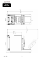
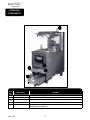
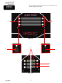
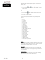
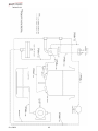
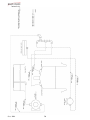
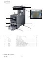
TECHNICAL
M A N U A L
VELOCITY SERIESTM PRESSURE FRYER
MODEL
PXE-100
R E G I S T E R W A R R A N T Y O N L I N E AT W W W. H E N N Y P E N N Y. C O M
HENNY PENNY
ELECTRIC PRESSURE FRYER
SPECIFICATIONS
Pot Capacity
Electrical
Heating
8 head of chicken - 24 lbs. (10.8 kg)
76 lbs. oil (34 Kg.)
208 VAC, 3 Phase, 50/60 Hz, 17 KW, 47.2 Amps
240 VAC, 3 Phase, 50/60 Hz, 17 KW, 40.9 Amps
480 VAC, 3 Phase, 50/60 Hz, 17 KW, 20.5 Amps
Two 8,500 watt electric immersion elements
A data plate, located on the back shroud behind the lid identifies the fryer model, serial
number, warranty date, and other information. Also, the serial number is stamped on the
outside of the counter top. See figure below.
Serial No.
Sept. 2014
2
PXE-100
Dimensions
Sept. 2014
3
OPERATING
COMPONENTS
1
3
2
4
5
Item
No.
Description
Function
1
Steam-Stack
Houses the dead-weight. Releases steam when pressurized
2
Fresh Oil Tank
Tops the vat off with fresh oil when low
3
Power Switch
Turns power to the unit ON/ OFF
4
Condensation Pan
Reservoir that hold excess condensation that drains from the vat
5
Oil Drain Pan
Oil is drained into this pan and then is pumped through filters to help
prolong the use of the oil
Sept. 2014
4
Control
Overview
This section gives a control board overview and explains all the
buttons, displays and features.
1
1
Figure 3-1
4
2
Figure 3-2
Figure 3-3
5
6
Figure 3-4
Sept. 2014
5
Control
Overview
(Cont.)
Fig.
Item
No.
Description
Function
3-1
1
Buttons
When the light is illuminated next to the button, this indicates this button
has a product or action that can be reached by pressing.
3-2
2
Menu Button
Pressing and holding this button will access the “MAIN” menu which
includes features such as filter, info mode, and programming.
3-3
3
Info Button
3-4
4
Arrow Displays
3-4
5
Plus Display
• Press this button once to display the pressure and temperature
• Press this button twice to activate the “WIPE” feature
• Press this button three times to get “LAST FILTER” information
When an arrow is displayed, this indicates there is another screen or option.
To access the next option/screen, press the button next to the desired arrow.
The plus sign is displayed when the value of the time/temp/letters can be
changed. Pressing the button next to the plus sign will increase the value.
Will be represented in the manual by: +
3-4
6
Minus Display
The minus sign is displayed when the value of the time/temp/letters can be
changed. Pressing the button next to the minus sign will decrease the value.
Will be represented in the manual by: -
Sept. 2014
6
HENNY PENNY
8 HEAD ELECTRIC PRESSURE FRYER
Fryer must be installed and used in such a way to prevent water from contacting the shortening.
This appliance is not intended to be operated by means of an external timer or a separate remote control
system.
This appliance is not intended for use by persons (including children) with reduced physical, sensory or
mental capabilities, or lack of experience and knowledge, unless they have been given supervision or
instruction concerning use of the appliance by a person responsible for their safety.
Sept. 2014
7
Section 1: introduction
1-1
SAFETY
The instructions in this manual have been prepared to aid you in learning
the proper procedures for your equipment. Where information is of
particular importance or is safety related, the words NOTICE, CAUTION,
or WARNING are used. Their usage is described below.
If a problem occurs during the first operation of a new unit, recheck the
Installation Section of the Operator’s Manual.
Before troubleshooting, always recheck the Operation
Section of the Operator’s Manual.
Where information is of particular importance or is safety related, the
words DANGER, WARNING, CAUTION, or NOTICE are used. Their
usage is described as follows:
SAFETY ALERT SYMBOL is used with DANGER, WARNING
or CAUTION which indicates a personal injury type hazard.
NOTICE is used to highlight especially important information.
CAUTION used without the safety alert symbol indicates a
potentially hazardous situation which, if not avoided, may result
in property damage.
CAUTION used with the safety alert symbol indicates a
potentially hazardous situation which, if not avoided, could result
in minor or moderate injury.
WARNING indicates a potentially hazardous situation which,
if not avoided, could result in death or serious injury.
DANGER INDICATES AN IMMINENTLY HAZARDOUS
SITUATION WHICH, IF NOT AVOIDED, WILL RESULT IN
DEATH OR SERIOUS INJURY.
Sept. 2014
8
1-1.
SAFETY
(Cont.)
Equipotential Ground Symbol
Waste Electrical and Electronic Equipment (WEEE) Symbol
1-2.
Proper Care
1-3.
Assistance
Sept. 2014
OR
Shock Hazard Symbols
OR
Hot Surface Symbols
As in all Henny Penny equipment, the unit requires care and
maintenance. Requirements for maintenance and cleaning
are contained in this manual and must be a regular part of the
operation of the unit.
Should you require outside assistance, call your local distributor
in your area, or call 1-800-417-8405 or 1-937-456-8405.for
Henny Penny Technical Support.
9
Section 2: Troubleshooting
2-1.
TROUBLESHOOTING
GUIDE
Problem
Power switch on but fryer
completely inoperative
Pressure not exhausting at
end of Cook Cycle
Relief valve vents
Pressure does not build
Cause
•
Open circuit
•
Correction
Solenoid or exhaust line clogged
•
•
•
Fryer plugged in
Check breaker or fuse at wall
Turn off and allow fryer to cool
to release the pressure in frypot;
have all lines, solenoid and
exhaust tank cleaned
•
Operating pressure too high
•
•
Deadweight clogged
•
Not enough product in frypot
•
Metal shipping spacer not removed
from deadweight assy.
•
Turn off and allow fryer to cool
to release the pressure in frypot;
clean deadweight; see Preventive
Maintenance Section
Place full capacity product in
frypot when Use fresh oil.
•
Pressure not programmed
•
Lid gasket leaking
•
•
Remove shipping spacer; see Unpacking Instructions Section
•
Check programming
Drain valve open
•
•
Reverse or replace lid gasket
Close drain valve.
•
High temperature limit tripped
•
Foaming or boiling over
•
•
Oil not draining
•
See Boil-Over chart on fryer and
beginning of Operation Section in
this manual
Drain valve clogged
Reset high temperature limit; see Operating Components Section
Follow Boil-Over procedures from
chart
Filter motor won’t run
• Motor overheated
Oil not heating
•
Push cleaning rod through open
drain valve
•
Reset motor; see Filter Pump
Motor Protector-Manual Reset
Section
More detailed troubleshooting information is available in the Technical Manual, available at www.
hennypenny.com, or 1-800-417-8405 or 1-937-456-8405.
Sept. 2014
10
2-2.
ERROR CODES
DISPLAY
“E-4”
“CPU TOO HOT”
“E-5”
“OIL TOO HOT”
In the event of a control system failure, the digital display will show an “Error
Message”. These messages are coded: “E04”, “E05”, “E06”, “E41”. A constant
tone is heard when an error code is displayed, and to silence this tone, press any of
the product buttons.
CAUSE
CORRECTION
Control board overheating
Turn switch to OFF position, then turn switch
back to ON; if display still shows “E04”, the
board is getting too hot; check for signs of
overheating behind the control panel; once panel
cools down the controls should return to normal;
if “E04” persists, replace the control
Oil overheating
Turn switch to OFF position, then back to ON;
if display shows “E05”, the heating circuits and
temperature probe should be checked; once the
unit cools down, the controls should return to
normal; if “E05” persists, replace the control.
Temperature probe failure
Turn switch to OFF position, then back to ON; if
the display shows “E06”, the temperature probe
should be checked; once the temperature probe is
repaired, or replaced, the controls should return to
normal; if “E06” persists, replace the control.
“E-6A”
“MAIN TEMP
PROBE FAILED”
(Open Circuit)
“E-6B”
“MAIN TEMP
PROBE FAILED”
(Shorted)
Reset high limit switch
“E-10”
“HIGH LIMIT
TRIPPED”
Sept. 2014
Solid state high limit has tripped
11
DISPLAY
“E-13”
“E-14”
“PRESSURE TOO
HIGH”
CAUSE
CORRECTION
• Replace pressure transducer
Pressure transducer failed
• Check deadweight chamber for any
obstruction
• Check the steam exhaust passage for
obstruction
Pressure is too high within the
frypot
“E-18A”
“LEVEL SENSOR
FAILED”
(Open Circuit)
• If circuit is open, check connection
The oil level probe has failed
• Replace probe
“E-18B”
“LEVEL SENSOR
FAILED”
(Shorted)
“E-41P”
“-1- LOST”
System data lost. Both the RAM
copy and stored copy of the settings
• Replace control board if occurs repeatedly
have been lost. Settings are reset to
default
“E-41S”
“SYSTEM DATA
LOST’
System data lost. Both the RAM
copy and stored copy of the settings
• Replace control board if occurs repeatedly
have been lost. Settings are reset to
default
“E-46C”
“INTERNAL SD
MEM ERR”
Issue with microSD chip
“E-46W”
“DATA SAVE
FAILED”
Sept. 2014
• Check to ensure chip is not ejected from slot
Unable to communicate and save
data to the microSD chip
Corrupt file
12
• Replace control board if occurs repeatedly
DISPLAY
CAUSE
CORRECTION
“E-47”
• Initialize the CPU board
“ANALOG SYSTEM Problem reading the A-to-D Analog
OR 12 VOLT
to Digital converter inputs
• Replace control board
FAILED”
“E-48”
“INPUT SYSTEM
ERROR”
• Replace control board
Failure of the CPU board
• Initialize the CPU board
“E-54C”
“MAIN TEMP
Fault on the CPU board
CIRCUIT FAILURE”
“E-54D”
“MAIN TEMP DSC
ERROR”
“E-70A”
“FAN JUMP
MISSING”
“E-70B”
“PWR SWITCH OR
WIRES FAILED”
“E-70C”
“DRN JUMPER
MISSING”
“E-82”
“SELCTOR VALVE
FAILURE”
Sept. 2014
• Replace control board
• Initialize the CPU board
Fault on the CPU board
• Replace control board
Jumper wire is loose or missing
from 15 pin connector
• Check connector for loose connection
Short in wires/ loose connection
• Check connection
Power switch may be faulty
• Replace power switch
Loose connection on the 15 pin
connector
Check connection
•
The selector valve failed calibration
•
or not responding
13
Check motor, encoder or wiring
If unit is not equipped with a selector valve
and gives this error, check settings in T-4
(Tech Mode) to confirm settings are correct.
DISPLAY
“E-84B”
“LID NOT
LOCKED”
“E-84C”
“PRESSURE
PIN DID NOT
ACTIVATE”
“E-84D”
“PRESSURE PIN
STUCK OR NOT
CONNECTED”
CAUSE
CORRECTION
• Lid handle not properly locked
• Failed electric lid lock motor
• Pressure pin did not fully
engage
• Cannot open lid-Pin is stuck
and has not dropped down
• Can open lid-wire may be
disconnected or monitoring
switch failed
•
Confirm handle is pushed all the way down
•
Test/ replace motor
•
Check to see if the pin is activating the switch
•
Test switch
•
If lid pin is stuck, remove lid cover and
manual free pin
•
Check wire connections and reconnect loose
wires
•
Replace faulty wires
•
Test switch
•
Replace switch if needed
“E-85A”
Extended limit switch is not
“LID LOCK EXT
working
SWITCH MISSING”
Test switch
“E-85C”
Retracted limit switch is not
“LID LOCK RET
working
SWITCH MISSING”
Test switch
• Sticking solenoid
“E-86B”
“PRESSURE STUCK • Clogged pressure exhaust port
ON”
• Faulty pressure transducer
“E-93”
“24V DC SUPPLY”
Sept. 2014
• Disconnected from control
• Short in drain motor or selector
valve motor
14
•
Test solenoid
•
Check ports and unclog if necessary
•
Test transducer
•
Check plug on back of control
•
Test motors
Section 3: Programming
Press and hold the
button until *MAIN* shows in the display.
Once the menu activates, release the button.
3-1.
MAIN MENU
The Main Menu options are displayed as follows:
1. FILTER
2. INFO MODE
3. USB/DATA
4. PROGRAM
5. CLOCK SET
x. EXIT MENU
This section shows how to access the programming
(“PROG”) menu that access the products, cook and special
program and tech mode.
3-2.
progRAMs
1.PRODUCTS
2.COOK MENUS
3.SPCL PROG
7.TECH MODE
8.STATS MODE
9.LANGUAGE
4.DATA COMM
5.HEAT CTRL
6.FLTR CTRL
x.EXIT MENU
Sept. 2014
1. PRODUCTS
2. COOK MENUS
3. SPECIAL PROGRAM
4. DATA COMM
5. HEAT CONTROL
15
6. FILTER CONTROL
7. TECH MODE
8. STATS MODE
9. LANGUAGE
x. EXIT MENU
3-3.
Special
Programming
This section shows how to access the Special Program area of
the controls in order to program cook menus, clock, and other
features.
1. Push and hold
until the display reads *MAIN*.
2. Enter the code: 1, 2, 3
3. Press the
again to access the next set of options.
4. Press 4 to enter the “PROG” menu. Use the buttons next to
the arrows on the display to access the next set of options.
Special Programming consist of the following:
5. Use the left or right arrows to navigate through the options.
SP-1 • TEMP UNITS
SP-2 • LANGUAGE
SP-3 • SYSTEM INIT
SP-4 • RADIO SYSTEM ENABLED?
SP-5 • AUDIO VOL (Loudness)
SP-6 • AUDIO TONE (Frequency)
SP-7 • MELT CYCLE
SP-8 • START-UP POLISH ENABLED?
SP-9 • START-UP GO WHERE?
SP-10 • COOK MENUS OPTION
SP-11 • COOK MENU BUTTONS
SP-12 • COOK DONE GO WHERE?
SP-13 • AUTO-MENU MINUTES
SP-14 • AUTO-MENU GO WHERE?
SP-15 • COOL TEMP
SP-16 • PROD PROG T1>T2>T3)?
SP-17 • BULK DISPOSE?
SP-18 • BULK SUPPLY?
SP-19 • COOKING: SHOW PSI?
SP-20 • CHANGE MGR CODE
SP-21 • CHANGE USAGE CODE
SP-22 • CLEAN-OUT TYPE
SP-23 • CLEAN-OUT TEMP
SP-24 • CLEAN-OUT MINUTES
SP-1 • TEMPERATURE DISPLAY UNITS
1. Use the + or - to change between Fahrenheit (F°) or Celsius
(C°).
SP-2 • OPERATION LANGUAGE
1. Use the + or - buttons to scroll through the list of languages.
SP-3 • SYSTEM INITIALIZE
1. Press and hold the button next to “hold->” for three seconds.
2. System will re-initialize back to default settings.
SP-5 • AUDIO VOLUME (Loudness)
1. Use the + or - buttons will adjust the volume of the speaker
between 0-10.
2. Press the button next to “test” on the display.
Sept. 2014
16
3-3.
Special
Programming
(Cont.)
SP-6 • AUDIO TONE (Frequency)
1. Press the + or - to adjust the frequency setting,
2. Press the button next to “test” on the display.
SP-7 • MELT CYCLE
Specify the desired Melt Mode heating cycle.
1. Use the + or - to select wither “Solid” or “Liquid”.
SP-8 • START-UP POLISH ENABLED?
Specify whether or not an automatic polish operation should be
performed as part of the normal, morning startup process.
1. Use the + or - to select either “YES” or “NO”.
SP-9 • START-UP GO WHERE?
Specify where the control should go after exiting Melt. Choices
are “STAY PROD”, “PREV MENU”, or go specifically to any of
the ten Cook Menus.
1. Use + or - to navigate through options.
SP-10 • COOK MENUS (Cook Menu Configuration)
1. Use the + or - buttons to navigate through cook menu options.
• “4+TITLE”
• “5+NEXT”
• “6 ITEMS”
See MENU OPTIONS for descriptions and examples.
SP-17 • BULK DISPOSE?
1. Use the + or - buttons to navigate through the three options:
• “NONE”
• “FRONT”
• “REAR”
2. “NONE”- Oil dispose is by draining into a disposal cart or
shuttle.
3. “FRONT”- Dispose by pumping through the front hose
connection by press and holding the illuminated button.
4. “REAR”- Dispose by pumping through the rear plumbing
connection.
Sept. 2014
17
SP-18 • BULK OIL SUPPLY?
3-3.
Special
Programming
(Cont.)
Sept. 2014
1. Use the + or - buttons to select either “YES” or “NO” for
whether or not a bulk oil supply is available for refilling the
ATO oil tank and vat with fresh oil.
18
3-4.
Info Mode
Info Mode offers various diagnostic displays. To access Info
Mode, either::
1. Press and hold
on the screen.
and
until “=INFO MODE=” flashes
Or
1. Press and hold
until “*MAIN*” flashes on the screen.
2. Press the “2. INFO” button.
Use the left or right arrow buttons to navigate through the
options:
•
•
•
•
•
•
•
•
•
•
•
•
•
•
•
•
•
•
•
•
E-Log
Last Load
Daily Stat
Review Usage
Activity Log
CPU Info
Temperatures
Digital Inputs-1
Digital Inputs 2
Inputs-3 (Bulk Oil Inputs)
Pressure Inputs
Fryer Outputs
Drain Valve Status
Selector Valve
Pump Outputs
Electric Lid Lock
Analog Inputs
Memory Info
USB Drive Status
ATO (Auto-Topoff) Level
E-Log
When E-Log is accessed, this displays the history of the previous
25 error codes starting with the most recent code first. Each code
includes the date and time that the error occurred.
Last Load
Information about the most recent cook cycle, including total
cook time, stopped early or left beeping too long, and min/max/
avg temperatures.
Daily Statistics
Operating statistics for each of the past seven days, including
hours on, cook cycles, number of filters and etc.
Sept. 2014
19
3-4.
Info Mode
(cont.)
Review Usage
Ongoing accumulation of operating statistics.
Stats accumulate until manual rest.
To reset (requires password), available by navigating all the way
to the bottom of the list.
Activity Log
History of Activity Log events:
• On/Off
• Start/Stop cook
• Filter
• Pan removed or replaced
CPU Info
Live temperature reading for the CPU (controller) temperature.
Temperatures
Live temperature readings for the Main oil temp., the Level
Probe temp., and the Bottom (bottom of vat) temperature.
The “Lvl” level probe shown here is the one actually in
use – upper or lower level probe -- as selected in Filter Ctrl
Programming mode.
Digital Inputs-1
√ = Signal present
- = No signal present
A = Power Switch
H = High Limit
D = Drain Switch Jumper
S = Power Switch Interlock
F = Fan Switch Jumper
Digital Inputs-2
√ = Signal present
- = No signal present
24dc = 24 DC Supply
Pan = Filter Drain Pan
*Lid = Lid Liner Pin
*Lid Liner Pin shows “OK” if pin is down.
Lid Liner Pin shows “PR” when pin is raised (under pressure).
Sept. 2014
20
3-4.
Info Mode
(cont.)
Bulk Oil Inputs
√ = Signal present
- = No signal present
DTF = Discard Tank Full
If √ is present, tank is full and cannot dispse to it.
HDP = High Dispose Pressure (optional)
If √ is present, dispose pumping caused high pressure.
AFR = ATO Fill Request (optional)
If √ is present, switch is asking to pump Bulk Supply Oil to refill
the ATO tank.
Pressure Inputs
Shows readings from the pressure transducer:
“OK” = Safe to open lid (not under pressure)
“PR” = Lid under pressure, cannot open
Fryer Outputs
* = On
- = Off
Pri = Primary Contactor
Ht = Heat (regulating) Contactor
Pr = Pressure Solenoid
Drain Control
Par = Partially open
Stp = Forced Stop
Opn = Fully Open
Cls = Fully Closed
The current state of the drain valve is indicated with a “►”.
The below “At” indicates the drain valve position.
0 = Fully Closed
20+ = Fully Open
Selector Valve (Bulk Oil Fryers Only)
If unit is not equipped with a Bulk Oil System, “No Selector
Valve” will read in the display.
“E=001” = Encoder Position
Lower left display shows the activity of the valve.
STPD
FWD
REV
Lower right display shows the current port position.
Sept. 2014
21
3-4.
Info Mode
(cont.)
Pump Outputs
* = On
- = Off
Fltr = Filter Pump
ATO = Topoff Pump
Bulk = Bulk Oil Supply
*Disp = Dispose Valve
*Dispose valve is optional
Electric Lid Lock
“R:” shows current request: Lock, Unlock
√ = request has been achieved and verified
“Mtr” = Motor
• - = Off
• “<-” = Retracting
• “->” = Extending
“R” / “X” = Retracted limit switch or Extended limit switch
currently pressed.
Analog Inputs
Analog input readings directly from the ADC chip.
Displayed as volts and as ADC counts(bits).
Use the Up and Down arrows to step through available inputs.
Memory Status (MEM INFO)
Shows the status and size of the control’s internal microSD
storage memory.
√ = Memory OK
X = Memory problem
Use the arrow buttons to scroll down to see free space, used
space and volume name.
USB Drive Status (USB INFO)
Shows the status and size of the USB flash drive, if present.
√ = Flash Drive OK
X = Flash Drive not present or drive error
Scroll down to see flash drive free space, used space and volume
name.
Sept. 2014
22
3-4.
Info Mode
(cont.)
ATO-Topoff Status (ATO LEVELS)
LVL = Levels
• “FULL”
• “LOW”
• “---”
Will show when an assessment is not possible.
Delta shows the temperature difference between the main probe
and the level probe.
Cnt = Count
Count shows how many ATO pulses have been generated in the
current topoff attempt.
Sept. 2014
23
3-5.
Tech Mode
1. Press and hold
until “*MAIN*” flashes on the screen.
2. Press and release
to go to the second list of menu options.
3. Press the “4.PROG” button.
4. Press the
to navigate through the menu options. Select
“7.TECH MODE”.
5. Enter the code 11221122.
Use the left or right arrow buttons to navigate through the
options:
T-1 • SOFTWARE ID’S
T-2 • META DATA
T-3 • FRYER TYPE
T-4 • FRYER HAS SEL VALVE
T-5 • PUSH BUTTON TEST
T-6 • DISPLAY TEST
T-7 • AUDIO TEST
T-8 • LVL TEMP OFFSET ADJ
T-9 • MAIN TEMP OFFSET ADJ
T-10 • BOTTOM TMP OFFSET ADJ
T-11 • SPARE TMP OFFSET ADJ
T-12 • CPU(degree) TEMP OFFSET ADJ
T-13 • INPUTS-1
T-14 • INPUTS-2
T-15 • INPUTS-3
T-16 • PRESSURE INPUTS
T-17 • OUTPUTS
T-18 • DRN VALVE
T-19 • SEL VALVE FWD/REV
T-20 • SEL VALVE PORTS
T-21 • PUMPS
T-22 • LID LOCK
T-23 • RADIO SYSTEM ENABLED
T-24 • RADIO COM
T-25 • ANALOG CHANNELS
T-26 • HEAT CTRL
T-27 • SAME KEY DELAY
T-28 • CHANGE TECH CODE
T-29 • DO TOTAL INIT
T-1 SOFTWARE ID’S
Shows th active version of software in the middle display.
T-3 FRYER TYPE
Shows what type of fryer (pressure or open) in the middle
display.
To change the fryer type:
1. Press the illuminated lower-left button to change from
Pressure to Open.
The model type will change in the middle display.
Sept. 2014
24
3-5.
Tech Mode
(cont.)
T-4 FRYER HAS SELECTOR VALVE
• If the unit is not equipped with a selector valve, the middle
display should read “NO”.
• If the unit is equipped with a selector valve, the middle
display should read “YES”.
• If incorrectly labeled, press the illuminated buttons next to the
+ or -.
T-5 BUTTON TEST
This section test all the buttons to confirm all are working
correctly. Press any of the non-illuminated buttons to enter the test
mode.
The screen will return to normal operation after 3 seconds of no
activity.
T-6 DISPLAY TEST
This section test all of the LED and display lights. Press the
illuminated button next to the type of test listed on the display.
• Press and hold the button on the LED test to test all the lights
on the buttons
• Press and release the buttons next to the display test options to
circulate through the different sections of the display.
T-7 AUDIO TEST
• Press the button next to “Start” to start the Audio volume test.
• Press and hold the button next to “Hold” to test the current
volume.
T-8 LVL TEMP OFFSET ADJ
Shows the current temperature of the oil at the level probe.
1. To adjust the temperature, press and hold the button next the
“Temp”.
2. With the button held, press the + or - to adjust the temperature
3. To adjust the offset, press and hold the button next to the
“Ofst”.
4. With the button held, press the + or - to adjust the offset.
Sept. 2014
25
3-5.
Tech Mode
(cont.)
T-9 MAIN TEMP OFFSET ADJ
Shows the current main temperature of the oil.
1. To adjust the temperature, press and hold the button next the
“Temp”.
2. With the button held, press the + or - to adjust the temperature
3. To adjust the offset, press and hold the button next to the
“Ofst”.
4. With the button held, press the + or - to adjust the offset.
T-10 BOTTOM TMP OFFSET ADJ
Shows the current temperature of the oil at the bottom probe.
1. To adjust the temperature, press and hold the button next the
“Temp”.
2. With the button held, press the + or - to adjust the temperature
3. To adjust the offset, press and hold the button next to the
“Ofst”.
4. With the button held, press the + or - to adjust the offset.
T-13 INPUTS-1
A
H D S F P M shows in the middle display.
A = Power Switch
H = High Limit
D = Drain Switch Jumper
S = Power Switch Interlock
F = Fan Switch Jumper
P = Not in use at this time
M = Not in use at this time
√ = signal present
- = signal not present
T-14 INPUTS-2
24dc = 24 DC Supply
Pan = Filter Drain Pan
Lid = Lid Liner Pin
√ = active
- = inactive
OK = lid pin is down (not under pressure)
Flashing PR = lid pin is raised (under pressure)
Sept. 2014
26
3-5.
Tech Mode
(cont.)
T-15 INPUTS-3 Bulk Oil
DTF, HDP, AFR show in the middle display
DTF = Discard Tank Full
√ = Tank is full; cannot dispose oil to tank
HDP = High Dispose Pressure
√ = Dispose pumping caused high pressure
AFR = ATO Fill Request
√ = Switch is asking to pump Bulk Supply Oil to refill the
ATO tank
T-16 PRESSURE INPUTS
This section shows the current psi of the lid. If “OK” is on the
display, the lid is safe to open. Otherwise, “PR” flashes showing
lid is under pressure
The bottom display reads “Lid Pin”. If “OK” is on the display, the
lid pin is down. Other wise, “PR” flashes showing the pin is raised
(under pressure).
T-17 OUTPUTS
Press the illuminated buttons next to the feature to test
Pri = Primary Contactor
Ht = Heat (regulating) Contactor
Pr = Pressure Solenoid
* = On
- = Off
T-18 DRN VALVE
NOTE: Be sure drain pan is in place before testing drain valve.
This section test the drain valve functions. A ► will show next to
the drain valves current state.
Par = Partially open
Stp = Forced stop
Opn = Fully open
NOTE: The number in the middle will display the position “At”
where the drain valve stopped from 00-20.
Cls = Fully closed
Sept. 2014
27
3-5.
Tech Mode
(cont.)
T-19 SEL VALVE FWD/REV
This section test the selector valve rotation position
Cst = Current state
Stp = Stop the selector valve rotation
Fwd = Press to rotate the selector valve forward.
Rev = Press to rotate the selector valve in reverse.
The “Enc” (encoder) will show when the encoder switch is
activated during rotation.
T-20 SEL VALVE PORTS
This section test the positioning of each port on the selector valve.
P0 = At pot
P1 = At dispose
P2 = At ATO refill
Enc = Encoder position
If the selector valve does not function properly, “FAIL” will show
on the middle-left display.
T-21 PUMPS
Press the illuminated button next to the function to start test.
* = On
- = Off
Fltr = Filter Pump
ATO = JIB Pump
Drn C = Drain Valve
T-22 LID LOCK
This section test the switches and motor for the lid lock.
Mtr = Press this to run a test on the motor
Stp = Stops the motor test
Lok = Rotates the motor to the lock switch. Once the lock is fully
engaged, a √ will show next to “Ex”.
Unl = Rotates the motor to unlock the lid. Once fully unlocked
and the switch is activated, a √ will appear next to “Re”.
Sept. 2014
28
3-5.
Tech Mode
(cont.)
T-23 RADIO SYSTEM
Section shows if the unit is equipped with a radio system.
To change the option, pres the + or - to select “NO” or “YES”.
T-29 TOTAL INIT
Press and hold the button next the “hold” on the display to
institutionalize the control board.
Sept. 2014
29
Section 4: MAINTENANCE
4-1.
INTRODUCTION
4-2.
MAINTENANCE
HINTS
This section provides checkout and replacement procedures, for various parts of the fryer. Before replacing any parts, refer to the Troubleshooting Section to aid you in finding the cause of the malfunction.
1. A multimeter will help you to check the electric components.
2. When the manual refers to the circuit being closed, the multimeter should read zero unless otherwise noted.
3. When the manual refers to the circuit being open, the multimeter
should read infinity.
Do not move the fryer with hot oil in the vat or filter pan. Severe
burns can result from splashing hot oil.
Sept. 2014
30
4-3.
Control Board
Replacement
Disconnect the power or electrical shock will occur.
1. Use a Phillips head screwdriver to remove the two screws
securing the control board to the front shroud.
2. Press in on the bottom of the board and rotate down until it rests
on the shroud.
3. Disconnect all the connectors on the back of the control board.
4. Use a 3/8in. nut-driver or socket and remove the nut securing the
ground wire to the control board.
5. Remove old control board.
6. Place new control board onto the unit with the tab inserted into
the slot. Let the control board rest on the shroud.
7. Finish control board installation in reverse order.
Sept. 2014
31
4-4.
Power switch
replacement
Disconnect the power or electrical shock will occur.
1. Lower the control board (see Control Board Replacement).
2. Mark the wires and disconnect.
3. Use a flat-blade screwdriver to press down on the locking tabs.
4. Pull the switch out of the shroud.
5. Place new switch in place.
6. Attach the wires to the new switch.
7. Slide new power switch into the shroud.
8. Secure the control board back in place.
9. Test operation.
Sept. 2014
32
4-5.
USB Port
Replacement
1. Remove the USB cap.
2. Use an adjustable wrench to remove the locking nut.
3. Remove the cap from the USB assembly.
4. Lower the control board (see Control Board Replacement).
5. Disconnect the USB plug from the receiver on the back of the
control board.
6. Pull USB port assembly out of the hole in the control board.
7. Place the new USB port assembly into the hole in the control
board.
8. Use one adjustable wrench to hold the USB port in place while
using another adjustable wrench to tighten the locking nut.
9. Plug the USB plug into the receiver on the back of the control
board.
10. Secure the control board back in place.
Sept. 2014
33
4-6.
High Limit
Thermocouples
Disconnect the power or electrical shock will occur.
1. Lift the lid and tilt back to lock into place.
2. Use a Phillips head screwdriver to loosen the heating element
spreaders.
3. Use a Phillips head bit to remove the screws from the left-hand
(from the front of unit) side panel.
4. Lower side panel and set aside.
5. Use a 1/2in. wrench to loosen the compression fitting.
6. Pull the thermocouple from the fitting.
7. Lower the control board (see Control Board Replacement).
8. Trace wires to the high limit modules on the sidewall of the
control board area.
9. Remove the wires from high limit module.
10. Use a 1/2in. wrench to remove the fitting from the vat wall.
11. Locate the new thermocouple and fitting.
12. Apply thread sealant to the fitting and thread into the vat wall.
Tighten with 1/2in. wrench.
13. Insert the new thermocouple into the compression fitting.
NOTE: Be sure the new thermocouple slides into the heating
element spreader.
14. Use a 1/2in. wrench to tighten the compression fitting onto the
thermocouple.
15. Use a Phillips head screwdriver to tighten the heating element
spreader.
16. Connect the new thermocouple wires to the high limit module.
17. Place side panel back in place and secure with the screws.
18. Secure the control board back in place.
Sept. 2014
34
4-7.
High Limit
Thermocouples
Disconnect the power or electrical shock will occur.
1. Lower the control board (see Control Board Replacement).
2. Locate the faulty high limit module on the left-hand (from the
front) side wall.
3. Mark all the wire locations.
4. Disconnect all the wires.
5. Use a 3/8in. socket or nut-driver to remove the nuts.
6. Remove the two (2) metal lock strips.
7. Slide the high limit module off of the mounting studs.
8. Slide the new high limit module onto the mounting studs.
9. Place the two (2) metal lock strips onto the studs and secure in
place with a 3/8in. socket or nut-driver.
10. Reconnect the wires as removed.
11. Secure the control board back in place.
Sept. 2014
35
4-8.
Primary
Contactor
Replacement
Disconnect the power or electrical shock will occur.
1. Lower the control board (see Control Board Replacement).
2. Mark the location of the wires.
3. Use a Phillips head screwdriver to remove the L1, L2 and L3
wires from the contactor.
4. Use a Phillips head screwdriver to remove the wires on the T1, T2
and T3 side of the contactor.
5. Disconnect the wires coming from the T1, T2 and T3 on the
contactor.
6. Disconnect the RS1 and RS2 yellow wires.
7. Use a 3/8in. socket or nut-driver to remove the nuts that secure the
contactor to the shroud.
8. Lift up on the contactor to remove it from the studs.
9. Place the new contactor onto the studs.
10. Use a 3/8in. socket or nut-driver to secure in place.
11. Replace wires as they were removed.
12. Secure the control board back in place.
13. Test operation.
Sept. 2014
36
4-9.
Heat Contactor
Replacement
Disconnect the power or electrical shock will occur.
1. Lower the control board (see Control Board Replacement).
2. Mark the locations of the wires.
3. Use a Phillips head screwdriver to remove the blue wires in A1
and A2.
4. Use a Philips head screwdriver to remove the coming from the
1L1, 3L2 and 5L3 side on the contactor.
5. Use a Phillips head screwdriver to remove the wires from the 2T1,
4T2 and 6T3 side of the contactor.
6. Use a 3/8in. socket or nut-driver to remove the two nuts on the
mounting plate.
7. Lift up on the contactor so the mounting plate clears the studs.
8. Place new contactor on the studs as the old contactor was
removed.
9. Use a 3/8in. socket or nut-driver to secure in place.
10. Reconnect all the wires where previously removed.
11. Secure the control board back in place.
12. Test operation.
Sept. 2014
37
4-10.
AIF Multi-Tab
Transformer
Replacement
Disconnect the power or electrical shock will occur.
1. Lower the control board see Control Board Replacement).
2. Label the locations of the wires and disconnect.
3. Use a 3/8in. nutdriver or socket to remove the four (4) nuts.
4. Remove the transformer from the studs.
5. Place new transformer onto the studs and secure with a 3/8in.
nutdriver or socket.
6. Reconnect the wires to the correct locations.
7. Close control panel.
8. Return power back to the unit.
9. Test operations.
Sept. 2014
38
4-12.
Control
Transformer
Replacement
Disconnect the power or electrical shock will occur.
1. Lower the control board see Control Board Replacement).
2. Locate the 5-pin connector leading from the transformer.
Disconnect the connector.
3. Use a 3/8in. socket and extension, remove the two (2) nuts that
secure the transformer to the shroud.
4. Lift up on the transformer to remove it from the studs.
5. Place the new transformer onto the studs.
6. Secure the transformer in place with a 3/8in. socket and extension.
7. Connect the 5-pin connector to the 5-pin connector jumper coming
from the control board.
8. Secure the wires with tie-strips to the existing wiring harness.
9. Secure the control board back in place.
Sept. 2014
39
4-13.
Pump Motor
Replacement
1. Remove the condensation pan (if PXE).
2. Remove the Fresh Oil Tank.
3. Remove the drain pan.
4. Use an adjustable wrench to remove the flex line and pipe
connections from both ends of the pump motor.
5. Use a Phillips head screwdriver to remove the two screws that
secure the plate onto the pump motor.
6. Mark the locations of the black wires.
7. Remove the black wires from the pump motor.
8. Use a flat blade screwdriver to remove the conduit retainer ring
from the pump motor.
9. Remove the conduit retainer and conduit from the pump motor.
Sept. 2014
40
4-13.
Pump Motor
Replacement
(Cont.)
10. Use a 1/2in. wrench to remove the two nuts on the mounting plate.
11. Lift up on the pump motor then pull it off the mounting plate.
12. Place the new pump motor onto the mounting plate so the hanger
bolts rest on the top lip and slide down so the studs are in line with
the holes in the pump motor base.
13. Use a 1/2in. wrench to secure the pump motor to the mounting
plate.
14. Use an adjustable to reconnect the flex lines to the correct port of
the pump motor.
Sept. 2014
41
4-14.
Remove the Lid
Cover
1. Use a phillips head screwdriver to remove the two (2) screws
located in the back of the lid.
2. Use a flat blade screwdriver to gently pry the front of the lid
cover so that the locater pegs slide out of their holes.
3. Lift up on the back of the lid cover.
4. Set the lid cover to the side.
5. The lid components are now accessible.
6. Reverse the previous steps to reinstall the lid cover.
Sept. 2014
42
4-15.
Lid Lock Motor
Replacement
1. Remove the lid cover (see Remove Lid Cover section).
2. Mark the location of each wire.
3. Disconnect the wires.
4. Use a phillips head screwdriver and 1/4in. wrench to remove the
two (2) screws and nuts.
5. Remove the motor from the mount.
6. Place the new motor onto the mount. Be sure the rod goes into
the tab.
7. Secure in place with the bots and nuts previously removed.
8. Reconnect the wires.
Sept. 2014
43
4-16.
Lock position
switches
Replacement
1. Remove the lid cover (see Remove Lid Cover section).
2. Mark the location of each wire.
3. Disconnect the wires.
4. Use a phillips head screwdriver to remove the two (2) screws that
secure the switch to the mounting plate.
5. Place the new switch in place.
6. Secure the switch with the two (2) screws previously removed.
7. Reconnect the wires.
Sept. 2014
44
4-17.
Flex Tube
Replacement
When installing new flex tubes, follow the listed guidelines to prevent
failures of the new flex tube.
1. Do not bend the flex tube within 4 finger widths of the end
fittings.
2. When bending the flex tube, the bend should not be smaller than
a golf ball in radius.
3. All flex tubes should be torque to 32.5 ft-lbs (finger tight, then a
¼ turn).
4. When tightening then flex tube’s fitting, hold the fitting that
the nut is tightening to, while torquing, to avoid twisting of the
flexible tube.
5. Discard any tube bent more than 3 times in the same area of tube.
Oct. 2014
45
Oct. 2014
46
Oct. 2014
47
Oct. 2014
48
Oct. 2014
49
Oct.. 2014
50
Section 5: Parts section
5-1
INTRODUCTION
This section lists the replaceable parts of the Henny Penny Velocity
Series Pressure Fryer.
5-2
GENUINE PARTS
Use only genuine Henny Penny parts in your fryer. Using a part of
lesser quality or substitute design may result in damage to the unit or
personal injury.
5-3
WHEN ORDERING
PARTS
Once the parts that you want to order have been found in the parts list,
write down the following information:
Example:
Item Number
2
Part Number
60241
Description High Limit
From the data plate, list the following information:
Example:
Product Number 01100
Serial Number 0001
Voltage
208
5-4
PRICES
5-5
DELIVERY
5-6
WARRANTY
Your distributor has a price parts list and will be glad to inform you of
the cost of your parts order.
Commonly replaced items are stocked by your distributor and will be
sent out when your order is received. Other parts will be ordered, by
your distributor, from Henny Penny Corporation. Normally, these will
be sent to your distributor within three working days.
All replacement parts (except lamps and fuses) are warranted for 90
days against manufacturing defects and workmanship.
If damage occurs during shipping, notify the carrier at once so that
a claim may be properly filed. Refer to warranty in the front of this
manual for other rights and limitations.
5-7
RECOMMENDED
SPARE PARTS FOR
DISTRIBUTORS
Sept. 2014
Recommended replacement parts are indicated with A or B in the parts
lists: A = parts to be stocked on service vans or trucks B = parts to be
stocked at the distributor/KES location. Inventory on all other parts not
identified, should be based upon usage in the territory. Please use care
when ordering recommended parts, because all voltages and variations
a marked. Distributors should order parts based upon comm voltages
and equipment sold in their territory.
51
8
7
1
2
3
4
6
5
Item No.
Part No.
A 1
96804
*
96613
*
26974
2
150598
3
150836
4
151783
5
90228
6
35154
7
89664
8
35227
Description
Quantity
ASSY-GM PXE100 CONTROL.............................................. --DECAL-PXE101................................................................... ASSY-SPEAKER..................................................................... FRESH OIL TANK.................................................................. CONDENSATION PAN........................................................... ASSY-DRAIN PAN PFX......................................................... --(see next page for breakdown)
CASTER-3.5 RIGID W/END BRAKE.................................... CASTER 4-INCH SWIVEL STEM......................................... GASKET-V STYLE FRYPOT LID......................................... ROLLER-LINKAGE SHAFT.................................................. * = Not Shown / AR = As Required
Sept. 2014
52
1
1
1
1
1
1
2
2
1
2
8
7
7
6
4
1
3
2
5
Item No.
Part No.
Description
A
B
151803
19004
NS04-005
92889
150739
152204
86349
12102
WELD ASSY-FILTER DRAIN PAN....................................... CASTER-2 IN SWIVEL MTG PLATE................................... SERRATED FLANGE LOCKNUT 1/4-20.............................. WELD ASSY-FILTER SECTION............................................ WELD ASSY-CARRIER CLIP................................................ WELD ASSY-PNP UNIT......................................................... O-RING -116 SUCTION LINE............................................... PHT FILTER ENVELOPES-100CT........................................ 1
2
3
4
5
6
7
8
Sept. 2014
Quantity
53
1
4
16
1
2
1
3
AR
1
2
9
8
7
6
5
4
3
Item No.
Part No.
Description
Quantity
A 1
B 2
B 2
B 2
B 2
B 2
B 2
3
4
5
6
7
8
*
9
154252
89225-001
89225-003
89225-004
89225-005
89225-006
89225-007
87119
87120
154736
154866
154839
154840
SC01-173
90085
ASSY-2 IN RTD PROBE......................................................... ELEMENT-HEATING 8.5 KW (208V)................................... ELEMENT-HEATING 8.5 KW (240V)................................... ELEMENT-HEATING 8.5 KW (480V)................................... ELEMENT-HEATING 8.5 KW (200V)................................... ELEMENT-HEATING 8.5 KW (230V)................................... ELEMENT-HEATING 8.5 KW (220V)................................... SPREADER-ANGLED............................................................ SPREADER-TAP PLATE........................................................ CLIP-HIGH LIMIT.................................................................. WELD ASSY-HI LIMIT CLAMP CLIP.................................. SPREADER-HI LIMIT ANGLED........................................... SPREADER-HI LIMIT TAP PLATE....................................... SCREW- #10-32 X 5/8 PH FHD SS........................................ O RING-CRUMB SWEEP....................................................... * = Not Shown / AR = As Required
Sept. 2014
54
1
2
2
2
2
2
2
3
3
2
2
1
1
8
2
1
2
3
4
5
Item No.
Part No.
Description
B
B
B
B
B
83581-002
84987
51795
65073
EF02-125
EF02-104
EF02-105
29509
86087
TS22-012
ME90-008
CONTROL-WATLOW HIGH LIMIT (208V)......................... HL SWITCH-MOMENTARY SPLASH PROOF.................... CONTACTOR-208/240 VAC COIL......................................... CONTACTOR-SQUARE D-24V............................................. BREAKER-PUSH BUTTON RESET...................................... FUSE HOLDER-20A 250V..................................................... FUSE 15 AMP.......................................................................... CONTACTOR KIT - 24VAC................................................... ASSY-24V/240V 75VA TRANSFORMER.............................. TRANSFORMER.................................................................... P&B T92 RELAY 12VDC COIL 30AMP................................ 1
*
2
2
3
*
*
4
5
6
*
Quantity
* = Not Shown / AR = As Required
Oct.. 2014
55
2
1
1
1
2
2
2
1
1
1
1
6
1
2
3
4
Item No.
Part No.
Description
A
A
94229
154252
79213
93968
INSULATION-POT LEFT SIDE............................................. ASSY-2 IN RTD PROBE......................................................... TRANSDUCER-PRESSURE 30 PSI...................................... THERMOCOUPLE-HI LIMIT................................................ 1
2
3
4
Quantity
* = Not Shown / AR = As Required
Sept. 2014
56
1
1
1
2
6
1
2
3
5
4
Item No.
Part No.
B 1
67583
B *
64218
2
-------
B 3
89780
B 4
90506-001
A 5
154252
B 6
91700
Description
Quantity
MOTOR-1/2 HP FILTER PUMP............................................. ASSY-FILTER PUMP-8 GPM................................................. FLEX LINES
(see chart below for lengths and numbers)
VALVE-ACTR DRAIN W/ 4 PIN CONN............................... VALVE-CHECK SAE 12 (max 200psi)................................... ASSY-2 IN RTD PROBE......................................................... ASSY-LH DRAIN PAN SW W/CONN................................... Part Number
77523-002
77523-011
Flex Line
Length
12in.
10in.
* = Not Shown / AR = As Required
Sept. 2014
57
1
1
1
AR
1
1
1
3
2
5
4
Item No.
Part No.
Description
B
94256
85145
94941
SC06-093
152276
94377
SLIDE-SHROUD VERTICAL................................................. VALVE-208-240V 3/4IN SOLENOID..................................... GASKET-DEAD WEIGHT HOLDER.................................... SCREW-10-32 X .500 KNURL PH HD.................................. ASSY-PULLEY CABLE AND LABEL.................................. HOSE-STEAM BOX CONDENSATE.................................... 1
2
3
*
4
5
Quantity
* = Not Shown / AR = As Required
Sept. 2014
58
2
1
1
3
2
1
1
2
3
Item No.
Part No.
Description
Quantity
1
2
3
16903
152101
16918
DEAD WEIGHT-12 P.S.I......................................................... 1
GASKET-STEAM BOX COVER............................................ 2
ORIFICE - 12 PSI.................................................................... 3
* = Not Shown / AR = As Required
Sept. 2014
59
1
2
3 4
3
2
Item No.
Part No.
Description
Quantity
1
2
3
4
59742
94256
152276
94259
ASSY - SAFETY RELIEF VALVE.......................................... SLIDE-SHROUD VERTICAL................................................. ASSY-PULLEY CABLE AND LABEL.................................. COUNTERWEIGHT BAR...................................................... * = Not Shown / AR = As Required
Sept. 2014
60
1
2
2
AR
1
2
3
Item No.
Part No.
B 1
74583
B 2
90506-001
3
-------
Description
Quantity
PUMP-OIL TOP OFF 230V..................................................... 1
VALVE-CHECK SAE 12 (max 200psi)................................... AR
FLEX LINES
(see chart below)
Part Number
85458-002
85458-003
Flex Line
Length
10in.
25in.
* = Not Shown / AR = As Required
Sept. 2014
61
2
8
8
1
3
6
4
5
7
4
Item No.
Part No.
Description
B
B
94825
49864
93778
151463
151464
94971
94322
93222
ASSY-CABLE AND STRAIGHT SKT................................... PAD-PRESSURE..................................................................... WELD ASSY-GEAR MTR 24VAC 60HZ............................... SWITCH-LID LOCKING........................................................ SWITCH-LID INTERLOCK................................................... ASSY-COILED LID CORD.................................................... WELD ASSY-LID WIRING RACEWAY................................ FILLER-CAM SLIDE.............................................................. 1
2
3
4
5
6
7
8
Quantity
* = Not Shown / AR = As Required
Sept. 2014
62
1
2
1
2
1
1
2
2
Henny Penny Corporation
P.O.Box 60
Eaton,OH 45320
1-937-456-8400
1-937-456-8402 Fax
Toll free in USA
1-800-417-8417
1-800-417-8434 Fax
www.hennypenny.com
*FM06-059*
Henny Penny Corp., Eaton, Ohio 45320, Revised 9-22-14