1
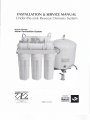
INSTAllATION & SERVICEMANUAL
Under-the-sink Reverse Osmosis System
Reverse Osmosis
Water Purification
System
~~
Member
WATER
QUALITY
INTERNATIONALSAFE TRANSIT ASSOCIATION
1283
I
.. ;:.~;::'.;:;;:~-=;:'
~~-~
';'~:':::':::,:'"':::::;i",
I
Made in USA
ASSOCIATION @
II
OEM
RO System Manual
T
hank you for choosing Reverse Osmosis Drinking Water System. Read carefully
and follow the instruction in this manual before proceeding with the actual
installation. Pay particular attention to all warnings, cautions and notes. Failure to
do so could result in personal injury or damage to the equipment or other property. Be
sure to follow any special plumbing codes in your area.
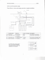
CHECK LIST:
I)
2)
3)
4)
5)
Reverse Osmosis Unit
Four colored tubing --black, blue, red, yellow.
Water storage tank, 4 gallon volume (2.5 gallon @40psi).
Installation kit: tank ball valve, drain saddle valve, feed water valve, faucet assembly.
Manual and warranties.
WT
OEJ~~
~
~
J1
1) Reverse Osmosis Unit
2) Water storage tank 4 gallon
RECOMMENDED
.
.
.
.
3) Installation Kit
TOOLS LIST
Variable speed drill
1/8" and 1/4" drill bits
7/16" drill bit 1;2"and 9/16 open-end wrenches ( or adjustable)
Phillips screwdriver
. Utilityknife
. Teflontape
).- WARNING: Do not use this RO system appliance to purify non-drinkable sources of
water that are unsafe or with water of unknown quality.
).- 'w ARN."ING:Never use hot water or freeze unit.
).- WARNING: Incorrect installation will VOID the warranty.
2
,I;;
RO System Manual
OEM
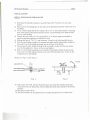
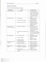
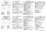
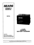
5 Stage RO System Filtration Process
TO
5--
S
ALJCET
--
-= C~A,\
:::- -< v ~T~
S-A[~
--
'RESSLJRE TAN<
3'(:::
S-I-<c=:
2i\i::: S-I-\=E
:S-
STAGE
Stage
Description
Service Time
1st stage
Sediment pre-filter
Carbon block pre-filter
GAC pre-filter
Membrane
Post carbon filter
6-12 month
12-18 month
12-18 month
24-36 month
16-18 month
2ndstage
3rdstage
4th stage
5thstage
3
v
'TED v-,ATeR
"'"
I
I
OEM
RO System Manual
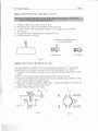
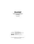
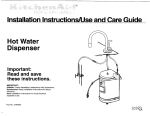
INSTALLATION QUICK LOOK
Please follow by 4 color coded tubing connection to complete installation
ROFaucet
/
//
7
A
+-Blue Tubin~
Yellow Tubing y,."-->
Black Tubing v."-->
r
~
I
Sto"ge T'nk
A
B
C
D
4 Connections
Item No.
RO Faucet
FU-NALR.C
Feed Water Valve VV-WNV-4
VV-WWC-l
Tank Ball Valve
VV-BLP014WJG
Drain Connector
VV-DSP014
Red Tubing v."
Color of Tubing
Blue
Red
Description
Pure Water to the Faucet
Feed Water to RO System
Yellow
Black
Pure Water to Storage Tank
Discharge Water to Drain
Se<u,",
,onMCtlon.". "mCle. I
CAUTION: When cutting supplied
tubes, predetermine the length by
measuring the distance between the
components to be connected.
CU' ,he .ube .ou'"
and cu,h cas.
'h. C-rlng '0 ,he 'ube "OC
tuDe
" .eeur" In cost"on
~
~
ur---
Ols,onne"ion
PU.h '°""
" lUStas e.$V
again"
bod,
.,,"" 'ube out of fltttng
4
.Q £:;:::.;;;
~~
I.
"
OEM
RO System Manual
INSTALLA TION
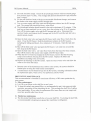
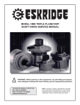
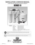
STEP 1: INSTALLING THE FAUCET
1) Determine the desired location for your RO faucet (FU-NALR.C) on your sink
surface.
2) Place a piece of masking tape or duct tape on the determined location where hole is to
be drilled.
.
3) Use a variable speed drill at slow speed with a 118"(3 mm) drill and drill a centering
hole in the center of the desired faucet location. Use lubricating oil to keep the drill
bit cool while drilling.
4) Enlarge the hole using a 14"(6.4 mm) drill bit. Use factory approved method or
approved plumbing practice to drill hole in sink.
5) Enlarge the hole to 7/16" (11 mm) diameter. Keep bit well oiled and drill slowly.
6) Pass the small rubber washers, the chrome base plate and the large rubber washer in
that order over the threaded mounting tube at the base of the faucet.
7) From under the sink, install the large metal (or plastic) washer and the star washer
over the threaded stem. Screw on the nut and tighten.
8) Sleeve over the brass compression nut and the white plastic ferrule (do not use the
brass one) over blue tubing and push to the end of the threaded stem. Screw on the
compressionnut and tighten.
.
Please see <Fig. 1> and <Fig. 2>
~.
ESCUTCHEONPLATE
aLACKRU88ERWA5HER-
,
.
1
COUNTER lOP
aLACKLOCAT1NG
WASHER-
LOCK WASHER
NUT
~
~~"
~~
<Fig. 2>
<Fig. 1>
9) Pull out the 3/8" O.D. red tube from RO faucet and insert the stainless steel long
reach sprout into the faucet base while holding the black faucet handle in horizontal
position.
10)The spout is 3600swivel.
11)The faucet handle can be pushed down for instant and pull out for continue flow.
5
1
OEM
RO System Manual
STEP 2: TAPPING INTO COLD WATER LINE
I) Locate cold water angle shut off valve underneath the sink and turn it off. Open cold
water faucet to release the pressure. On single handled faucets, the hot water may
have to be turned off to prevent any hot water cross over. If water continues to come
out of faucet with angle valve turned off, the house main will have to be turned off.
2) Locate feed water adapter in the installation kit. The angle needle valve(VV-WNV-4)
should be installed into slip joint adapter (VV-WWC-I) before assembly is connected
to feed water line. See <Fig. 3> (Teflon tape must be used on angle valve to prevent
leaks).
3) Disconnect the cold water riser tube and install the slip joint adapter.
y-
0
~
7
~
WWNV~
~~eJ
'T
..
.
~
LJ
W.WWC-1
.
~
IT
~
\.L!.J
lj
Flex line
!
~
~
""""
Solid
copper
line
<Fig.3>
<Fig. 4>
4) Please follow by <Fig. 4> for flex line and solid copper riser installation.
a) Flex line:
Loosen nut and separate cold water riser tube from faucet shank. Gently bend riser
tube so that slip joint fits onto faucet shank. Replace the existing
cone washer with new washer provided in installation kit onto cold water riser tube.
Reinstall riser tube onto slip joint adapter and tighten.
b) Solid copper riser tube:
Procedure as flex tubing except you must cut a piece of the riser tube about %" or 1"
so the slip joint adapter can fit between faucet and riser tube (Teflon tape must
be used on slip joint adapter to prevent leaks).
4) Connect red tubing to angle needle valve (VV-WNV-4).
6
OEM
RO System Manual
STEP 3: MOUNTING THE TANK BALL VALVE
id'iof sJOragetan~
Ii
I) Unplug the plastic cap on the top of the tanle
2) Wrap the thread 3 times with plumbers (Teflon) tape only.
3) Connect the ball valve to the thread. Make sure it is tight but not over-tight.
See <Fig. 5>.
4) Connect the yellow tubing from to the tank ball valve
5) Turn the tank ball valve off.
Top view oftank ball valve
(VV-BLPOI4WJG)
4G
0
001
~
Off Position
On Position
<Fig. 5>
STEP 4: MOUNTING THE DRAIN CLAMP
The drain clamp (VV-DSP014) will fit most standard drain pipe 1/4". It should be
installed above the trap and on the vertical or horizontal tailpiece. See <Fig. 6>
1) Position the drain saddle in desired location, mark spot through thread outlet, remove
saddle.
2) Drill W'(6.3mm) hole into the drain pipe above the water line of trap.
3) Align the hole drilled in the drain pipe with the drain saddle using a drill bit or other
narrow straight object and tighten clamp.
4) Make sure to align drain saddle to drilled hole. Attach drain saddle to drain pipe and
tighten the two screws evenly. See <Fig. 7>.
5) Connect black tubing to drain clamp.
~
DrainPipe
~RO"~
1IIIIIill.il!!"illll!
bI
Never Mount
Here
td
<Fig. 6>
1IIIIIIIIII11111111111111111U
<Fig. 7>
7
II
I
II
OEM
RO System Manual
STEP 5: SYSTEM START UP
1) Turn on the cold water supply and the under sink feed water valve (VV-WNV-4) but
close the tank ball valve (VV-BLP014WJG).
2) Open RO faucet (FU-NALR.C) (black lever to the up position) for continue flow.
3) Check system for leaks, tighten as necessary. ,
4) After 5 minutes, the water will start to drip out of the RO faucet. Let it drip for about
10 minutes and then flip the handle to the closed position. Turn on the tank ball valve
now. It will now take several hours (2-3) for the storage tank to fill, depending on the
local water pressure.
5) After the tank is full (you will hear the water stop), flush the system by placing the
RO faucet in the open position until the water is completed discharged.
6) Upon complete discharge of storage tank, flip handle to closed position on RO faucet
and let the refilling ptocess begin. This process could take 2-3 hours to complete.
7) After the second tank is filled, you may enjoy the pure water.
8) Check leaks daily for first week and periodically thereafter.
9) You may notice that the water may be milky colored during the first week. It is the air
bubble in the water. It is normal and safe.
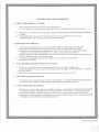
CLEANING PROCEDURES
The following system and tank cleaning procedures are recommended every 12-18
months.
1) Shut off the source water supply to the RO system.
2) Open the RO faucet and depressurize the RO system and storage tank.
3) Remove pre-filter cartridges, post-filter cartridges, and RO membrane. Discard or
prepare for clean. If the RO membrane element is to be reused, disinfectant solution
should be introduced into the permeate tube outlet sufficient to remove biofilm in this
vulnerable area, before reinserting the membrane into the housing.
4) Wash the internal housing areas with warm soapy water using a clean brush (do not
scratch the surface of the housings). Be sure to clean o-ring grooves thoroughly.
Remove the existing o-ring. Discard o-ring or prepare for cleaning.
5) Rinse off all housing pieces with clean water to remove soap.
6) Replace o-rings, and lubricate per manufacture's instruction.
7) Pour recommended amount of disinfection solution into each of the clean housings
and replace housing on the RO system.
8) Disconnect RO storage tank from the system.
9) RO storage tank cleaning procedure:
Recommended items:
Field Sanitizing Device
. Tank sanitizer feeder or small filter housing with
fittings and tubing, see <Fig. 8>
i))"'. Disinfectant solution
. Pressure gauge and air pump
~
8
;,{,:
<Fig. 8>
OEM
RO System Manual
I
a) The tank should be empty. Check the air precharge pressure with an accurate gauge
(low pressure type 0-12 Ibs.). The average tank pressure should be 6-8 psi (when the
tank is empty).
b) Fill the tank sanitizer feeder with the recommended disinfectant dosage, and connect
the feeder to the water supply and RO storage tank.
c) Turn on water supply and force water and disinfectant solution into the RO storage
tank. The storage tank should feel heavy when filled.
d) The disinfectant solution should remain in the tank a minimum of 10 minutes. If the
tank has not been sanitized in over a year, leave the solution in for 20 to 30 minutes.
Turn off the water supply valve and the RO storage tank valve. Disconnect the
sanitizer feeder, and connect the RO storage tank to the RO unit (the tank ball valve
should remain closed).
10)Open the feed water valve and open the RO faucet until water flow s freely from the
spout. Close the RO faucet. Hold the disinfectant solution in the RO system,
including the tubing and faucet, for a minimum of 10 minutes. Open the tank ball
valve.
11) Shut off the feed water valve and open the RO faucet. Let water run out until the
flow stops at the RO faucet.
12)Open the feed water valve. Let water flow freely from the faucet for three minutes.
Shut off the water at the source water supply with RO faucet open.
13)When the flow of water has stopped at the RO faucet, remove the filter housing
sumps and membrane housing from the RO system. Replace the filters and
membraneaccordingto the servicelife.
.
14)Replace the housings on the RO system. Open the source water valve and allow the
water to flow from the faucet.
.
.
Because some of the disinfectant may still be in the system, the system should be
flushed prior to using the water human consumption.
A maintenance record should be kept for the RO system, including information about
the replacement parts, when service was performed, and by whom.
PREVENTIVE MAINTENANCE
This recommendation is intended for maximum efficiency of RO water production by
your system.
1) Filter maintenance
a) It is OK to put filters on the shelf for several years.
b) To keep the sealed, non-opened filter, we recommended to put it into some air-tight
container, preventing it from absorbing the air. This prolongs the shelf life of carbon
filter (particularly, if you order the replacement filter more than one year usage) and
avoid any possible odor from the air.
2) Membrane maintenance
a) The dry packed membrane usually has a two-year shelflife. To prolong the shelflife,
we recommended to keeping non-opened dry membrane in refrigerator.
9
OEM
RO System Manual
b) Once being used, we recommended you to run the RO system every day, at least 10,15minutes (about 1 gallon or 4 liter drinking water). This helps to maintain the
membrane performance.
c) If not use RO system for weeks, drain the storage tank first. Fill the tank and drain it
twice. And then your RO system is ready to use.
3) Filter and membrane change procedures:
a)
b)
c)
d)
Shut off the water supply.
Turn off the tank ball valve by turning 90 degree.
Open RO faucet to up continue flow position.
Lift the filter housing up I" and slid the housing wench in (not supply with systems).
Use one hand to hold the system and the other hand to turn the wrench clockwise to
open the housing.
e) After opening the housing, remove the used filter and put the new filter into the
housing. Make sure the O-ring is placed and turn the housing counter-clockwise to
close.
t) Repeat previous step on the second filter change.
g) Turn on the water supply and make sure no leaks.
h) Let the water drip from faucet for about 10 minutes. If the water flow is less than 1
.
cup (8 oz. or 240ml) per minute,it maybe a signalto membrane.
i) Membrane change procedures:
. Unscrew the cap of the membrane housing.
. Slid out the used membrane and discard.
. Insert the new membrane with 2 o-rings into housing first, the black brine seal around
membrane latter. Be sure it is fully seated into bottom end
. Screw cap back on to the membrane housing, make sure o-ring is still in place.
. It may take 10-20 minutes for new membrane to run to normal flow.
If the water flow is OK, then turn on the tank ball valve. After 1 minute, turn off the RO
faucet and complete the filter change procedures.
10
::::J
OEM
RO System Manual
TROUBLE SHOOTING
Note: Turn off the system before servicing.
PROBLEM
Milky colored water
CAUSE
.,/ Air in system
0
Noise from faucet
.,/ Air gap faucet
0
.,/ Location of drain saddle
0
.,/ Restriction in drain line
0
.,/ System just starting up
0
Small amount of
water in storage tank
Slow production
SOLUTIONS
Air in the system is a
normal occurrence with
initial startup of the RO
system. This milky look
will disappear during
normal use within 1 to 2
weeks.
Will disappear after
system shut down
Relocate the drain to
above water trap.
Blockage sometimes
caused by debris from
garbage disposal or
dishwasher
Normally it takes 2-3
.
.,/ Air pressure in storage tank is
low
0
.,/ Low water pressure
0
0
.,/ Crimps in tubing
.,/ Clogged prefilters
.,/ Fouled membrane
0
0
Water taste or smell
Offensive
.,/ Post carbon is depleted
.,/ Fouled membrane
.,/ Sanitizer not flushed out
0
0
0
No drain water
Leaks
.,/ Clogged flow restrictor
.,/ Fittings are not tightened
0
0
.,/ Twisted O-ring
.,/ Misalignment of hole in drain
saddle
0
0
11
hours to fill tank. Low
water pressure and/or
temperatures can reduce
production rate.
Add pressure to storage
tank. The pressure should
be 8-10 psi when the tank
is empty
Add a booster pump
Make sure tubing is
straight
Replace pre filters
Replace membrane
Replace post carbon
Replace membrane
Drain storage tank and
Refill it overnight
Replace flow restrictor
Tighten fittings as
necessary
Replace a o-ring
Realign drain saddle
I'
@].@]
I~
~I
~
~
~
~
~
~
~
~
~
LIMITED TWO YEAR WARRANTY
1. WHAT YOUR WARRANTY COVERS:
~
~
Reverse Osmosis Systems are warranted to the original owner to
be free of defects in material and workmanship from the date of manufacture for two years as follows:
~
1) Manufacturerwill,withintwo yearsof purchase,replacethe defectedparts(excludingthe replaceablefilters)at
@I
@I
2)
no charge.
~
~
~
@I
2)
~
3.
~
also have other rights which vary from state to state.
Systems must be installed and operated in accordance with manufacturer's
.
the owners manual.
~
2)
4.
~
~
~
~
~
~
~
~
@I
@I
~
The following operating conditions must also be followed for this warranty to be valid.
OBTAINING WARRANTY SERVICE:
For warranty service, ship your Reverse Osmosis unit (less tank) to your dealer, freight and insurance prepaid,
with proof of date of original purchase and Return Merchandise Authorization (RMA) No.
5.
~
~
ii!J
recommended
WHAT REVERSE OSMOSIS SYSTEMS WILL NOT DO:
1) Warranty is void if product failure or damage results from freezing, neglect, misapplication,
fouling with sediment or scale or failure to operate the system in accordance with the instructions contained in
~
@I
~
~~~~.
@I
~
~
~
~
~
of replaceable filter varies with local water and is thus not warranted.
The performance and functioning of your drinking water system is directly related to the quality
of the being treated and the particular application in which it is used. Therefore, manufacturer's liability
is limited to the cost of repair or replacement (at our option) of any defective part, does not
include incidental or consequential damages of any kind. The warranty gives you specific legal rights and may
@I
~
@I
1) Systemmustbe maintainedandservicedwithmanufacturerapprovedreplacementparts andfilters.
~
~
~
~
.~
@I
The replaceable filters are warranted for defects in material and workmanship only. Service life
2. CONDITIONS OF WARRANTY:
~
~
~
~
~
LIMITATIONS AND EXCLUSIONS:
Manufacturer will not be responsible for any implied warranties, including those of merchant ability and fitness
for a particular purpose. Manufacturer will not be responsible for any incidental or consequential damages,
~
~
~
~
~
@I
@I
@I
including travel expense, telephone charges, loss of revenue, loss of time, inconvenience, loss of use the
equipment and damage caused by the equipment and its failure to function properly. This warranty sets forth all
@I
@I
~
of manufacturer's responsibilities regarding this equipment.
~I
~
-~
.~
~
~
~
~
~
@
@].@]
~
CAT-MAN-OEM-0912007/5M