1
Document ID: 2141056
Page 1 of 6
| Canyon, Colorado, (VIN S/T) Service Manual |
Driver Information and Entertainment | Cellular, Entertainment, and Navigation | Repair Instructions |
Document ID: 2141056
2009 Chevrolet Colorado Pickup - 2WD
Communication Interface Module Replacement
Removal Procedure
Note: The vehicle communication interface module (VCIM) has a specific set of unique
numbers that tie the module to each vehicle. These numbers, the 10-digit station
identification (STID) and the 11-digit electronic serial number (ESN), are used by the
National Cellular Network and OnStar® to identify the specific vehicle. Because these
numbers are tied to the vehicle identification number of the vehicle, you must never
exchange these parts with those of another vehicle.
1. Ensure the ignition switch is in the OFF position.
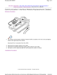
2. Remove the service panel located on the right side of the instrument panel (I/P).
© 2011 General Motors Corporation. All rights reserved.
http://localhost:9001/si/showDoc.do?docSyskey=2141056&pubCellSyskey=149736&pub...
3/27/2011
Document ID: 2141056
Page 2 of 6
3. Disconnect the VCIM electrical connectors as necessary.
4. Remove the screw retaining the VCIM to the bracket.
http://localhost:9001/si/showDoc.do?docSyskey=2141056&pubCellSyskey=149736&pub...
3/27/2011
Document ID: 2141056
Page 3 of 6
5. Release the tab (1) on the bracket.
6. Remove the VCIM from the bracket.
http://localhost:9001/si/showDoc.do?docSyskey=2141056&pubCellSyskey=149736&pub...
3/27/2011
Document ID: 2141056
Page 4 of 6
7. Remove the VCIM from the vehicle.
Installation Procedure
1. If replacing the VCIM, record the 10-digit STID number, and the 11-digit ESN number from
the labels on the new module.
Caution: Refer to Fastener Caution in the Preface section.
2. Install the VCIM to the bracket ensuring the retaining tab (1) is fully seated.
http://localhost:9001/si/showDoc.do?docSyskey=2141056&pubCellSyskey=149736&pub...
3/27/2011
Document ID: 2141056
Page 5 of 6
Tighten
Tighten the screw fully driven , seated and not stripped.
3. Connect the VCIM electrical connectors as necessary.
4. Install the service panel.
Note: After replacing the VCIM, you must reconfigure the OnStar® system. Failure to
reconfigure the system will result in an additional customer visit for repair. In addition,
pressing and holding the white dot button on the keypad will NOT reset this version of the
OnStar® system. This action will cause a DTC to set.
5. Reconfigure the OnStar® system. Refer to Control Module References.
http://localhost:9001/si/showDoc.do?docSyskey=2141056&pubCellSyskey=149736&pub...
3/27/2011
Document ID: 2141056
Page 6 of 6
6. When replacing the communication interface module be sure to transfer Bluetooth Antenna, if
equipped.
http://localhost:9001/si/showDoc.do?docSyskey=2141056&pubCellSyskey=149736&pub...
3/27/2011