1
Service Technician Manual
GE REFRESH AHNB20WBUS / AHNB11WBUS DEHUMIDIFIER
Content
1
Preface
2
Outer Parts
3
How the Dehumidifier Works
4
Installation
5
Brief Operations
7
Fast Function Test
8
Disassembly of Outer Parts
9
Disassembly of PCBA and Fan Motor
10 Disassembly of Defrost Sensor,
Micro Switch, Compressor Terminals
11 Locating Refrigerant Leaks /
Evacuation and Recharging
12 Replacement of Refrigerant System
13 Normal Conditions and User Checklist
14 Complaints and Solutions Matrix
15 Exploded Component Views
16 Part List
17 Circuit diagram
P/N 784002370-00
Preface
Purpose
This service manual provides various service information, containing the mechanical,
electrical and electronic parts.
Be sure to read the manual prior to servicing the unit.
Safety Precaution
1. When servicing the unit, unplug the power cord.
2. After servicing the unit, make an insulation resistance test to protect the customer
from being exposed to shock hazards. Isolation resistance: 1M (500V, 1sec.)
Specifications
Model
Function
Capacity
(30 C, RH80%)
AHNB20WBUS
For ambient temperature 5 - 35 C
20L/day
Power AC
Power
Consumption
Control
AHNB11WBUS
11L/day
220-240V ac/50Hz
200W
370W
Micro-control automatic defrosting,
2 fan speeds,
Unique air purifying function,
Auto pause when bucket is full.
Net Weight
Dimensions
Refrigerant
1
10.7 Kg
10 kg
W310 x D270 x H575 mm
HFC-134a
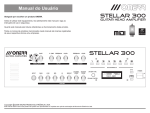
Outer Parts
The Control Panel
Ionizer
(AHNB20WBUS)
Timer Key
The Body
Air Outlet
(Five steps
adjustable)
Timer
Indicators
Function
Indicators
Condition
Indicators
Function Key
ON/OFF
Handle
Charcoal Filter
Air inlet (back)
Drain Connector (back)
Handle to lift the bucket
Water Level
Indicator Window
Bucket
(use the handle to carry it)
(refer to Page 5)
2
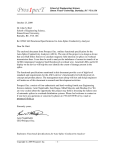
How the Dehumidifier Works
The dehumidifier, as shown in the figure, consists of a small refrigerant system
and a fan. The fan pulls humid air from the room, across the cold evaporator
where the water drips off into a water bucket or a drain hose. The air then passes
over the warm condenser and slightly increases in temperature.
Dry and Warm air out
Condenser
Evaporator
Fan
Humid air in
Drain Pan
Drain Passage
Bucket
Compressor
Working Principle
Side View
Defrosting Control
Under temperature around 5 C, frost may generate on the evaporator. A defrost
sensor fixed on the evaporator will sense the icing condition and stop the
compressor but remain the fan, through microcomputer-control, for 6 minutes
defrosting. Then retrieve the compressor running at least 12 minutes.
3
Installation
To Set the Unit
Keep a clearance of at least
5 cm at the back of the unit
for air intake.
Do not insert small
objects into the
cabinet : this may
damage the unit.
Put the machine on a stable horizontal
surface or water may leak.
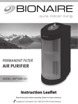
Space and Capacity
Dehumidifying Capacity (L/day)
30 C, 80%RH 27 C, 60%R
b) Generally, this 20(11) L/day (30 C, 80%)
unit can serve a room of 60(32) square meter.
c) For a high moisture or open place, the
capable area may be less than 50(26) square
meter.
d) For a low moisture or closed place, the
capable area may be larger than 70(37) square
meter.
For a room larger than 70(37) square meters,
it is recommended to use 2 or more units
at different corners.
12
10
8
6
4
2
Room Area (m2)
Continuous Drainage
You may use a hose with an outer diameter of 12.7 mm
(1/2 inch) for continuous drainage :
1. Use a screwdriver to remove the knockout at the back.
Attach the tubing to the connector through the hole.
2. The tubing should be lead to the drain with no sharp
bends.
Back
To Move the Unit
1. To move the unit, use the retractable handle.
2. Unplug the cord and empty the water bucket before moving the unit.
3. Before operating the unit, make sure the bucket is well in place.
4
Brief Operations
Before Using
a) Turn the multi-directional air outlet before operating the unit.
b) Must fit the bucket properly.
運轉操作
Operating
9
D
8
7
6
5
4
C
3
B
2
1
A
(AHNB20WBUS)
1. Plug the power cord to the proper power source; press ON/OFF key A
to start the unit.
2. Press the select key B to activate the functions 5 4 and 3 , in this order.
3. Press the timer key C to select the appropriate turn off time. If Timer
Indicator doesn't on, the unit is not programmed to turn off automatically.
4. Press the Ion key D (AHNB20WBUS) to start the Ionizer. Press the ION key
again to stop the ionizer.
5. Press the ON/OFF key A again to turn off the unit. (Unplug the cord when the
unit is not expected to be used for a long period of time.)
Note: A protection mechanism prevents the compressor to start within 3 minutes after the unit is turned off.
運轉操作
Function Keys
5
A ON/OFF
B
Function Key
C Timer Key
D
Ionizer (AHNB20WBUS)
Brief Operation
Indicators
1 Full: Blinks when the bucket is full or not in place. Please empty the
2
3
4
5
6
7
8
9
bucket or restore it in the correct position.
Defrost: Blinks when defrosting. It will auto-return to dehumidifying.
Air Filter Only: The unit only filters the air and does not dehumidify.
High: Lit when running at high dehumidification speed.
Low: Lit when running at normal dehumidification speed.
8 Hours: The unit will be shut-off automatically after 8 hours.
4 Hours: The unit will be shut-off automatically after 4 hours.
2 Hours: The unit will be shut-off automatically after 2 hours.
Ionizer: Lit when the lonizer is on. (AHNB20WBUS)
To Empty the Bucket
(1) When the bucket is full of water, the unit stops and the "Full" indicator blinks.
(2) Do not remove the bucket immediately as the unit may still working or shutting
down. Removing the bucket too fast may cause some water dripping.
(3) To remove the bucket, pull it out and lift it carefully.
(4) After pouring out the water, clean the bucket and restore in place.
To Pull out
To lift
To restore
6
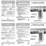
Fast Function Test
The following procedure is for
maintenance test only.
AHNB20WBUS
Start when unplugged
1. Press the "Select" button
2. Plug the machine
3. Release the Select button
All LED
Hi-Fan
Ion
ON
Select button
OFF
NO
Change (or Repair)
CPU PCBA or Relay
PCBA or Fan Motor
or Ion. (AHNB20WBUS)
YES
Press and release the
"Select" button again
Lo-Fan
Compressor
ON
NO Change (or Repair) CPU PCBA
or Relay PCBA or Relay PCBA
or Fan Motor or Compressor
YES
Press and release the
"Select" button again
Lo-Fan
Compressor
OFF
NO
YES
Two Red LED Flash?
YES
Pass Test
7
NO Change (or Repair)
CPU PCBA or Defrost
Sensor
"Full" indicator and "Defrost" indicator blink.
Disassembly of Outer Parts
Air Filter
1. Turn off the machine and pull out the filter at the back.
2. Do not wash the Charcoal Filter. Please replace it
with a new filter after 3 to 6 months (recommended).
3. Contact with your dealer should you need a new Charcoal Filter.
Bucket
Turn off the unit first.
1. To remove the bucket, first pull it out.
2. Lift it by the handle inside the bucket.
To reinstall, refer to the above removal procedures.
Pull out
Lift
Case
Unplug the cord first.
1. Remove the bucket.
2. Remove the filter cover.
3. Remove the handle by push slightly inward.
4. Then, remove 15+2 screws which fasten the
front case and rear case and the base.
To reinstall, refer to the above removal procedures.
8
Disassembly of PCBA and Fan Motor
PCBA (CPU PCBA, Relay PCBA)
First remove the case. (Refer to Page 8)
Remove the screws that fasten the PCBA.
Unplug the wires from connectors.
To reinstall the components, refer to the above removal procedures
and the wiring diagram.
RLY2 RLY3
capacitor
capacitor
RLY4
(AHNB20WBUS)
Fan and Fan Motor
First remove the case. (Refer to Page 8)
Remove the nut and washers which fasten the fan. Note the left-hand screw
shaft. Then, remove the screws which fasten the fan motor.
To reinstall, refer to the above removal procedures.
9
Locating Refrigerant Leaks / Evacuation and Recharging
Refrigerant Leaks
An undercharge of refrigerant is usually caused by a leak in the system. Such leaks must
be located and repaired before evacuating and recharging, as simply adding refrigerant
or recharging will not permanently correct the problem and may lead to a compressor
burn-out. If a leak is suspected, attempt to find it before opening the system.
Leaks, particularly small ones, are easier to find if the surrounding air is not contaminated
with refrigerant from the system. Leaks are more easily found if the system is pressured
to at least 75 p.s.i. gauge. If necessary, attach a line-piercing valve to the compressor
process tube and add enough refrigerant to test. Most leaks can be found with a Halide
torch. However, for very small leaks, it may be necessary to use an Electronic Leakage
Detector, or the bubble method, to pinpoint the leaks.
Note: Be sure the system has a positive pressure before using the bubble method of
leak testing. A vacuum within the system could draw in moisture and other contaminates.
Evacuation
Cut compressor process tube, purge system slowly so as not to blow out system oil.
Purge to a well ventilated area or outside atmosphere. Use solder rod to weld on a new
process tube.
Connect vacuum pump to compressor through process tube. Start vacuum pump, slowly
open manifold valve A and B and leave valve C closed. Operate vacuum pump until
vacuum of 600 microns is obtained. Close vacuum pump suction valve B and observe
vacuum gauge for a few minutes. A rise in pressure would indicate a possible leak or
moisture is still present in the system.
With valve B still closed, stop the vacuum pump. Open valve C and allow enough
refrigerant to enter the system that would raise the pressure to 40 to 50 p.s.i. gauge
pressure. Close valve C. Leak test low side of the system. Run compressor for a few
minutes then leak test the high side. There should be no leaks. You are now ready for
final evacuation.
Recharging
11
After evacuation, leaving valve B closed,
observe liquid level in charging cylinder.
Check rating label for correct refrigerant
charge. Open valve C and allow proper
charge to enter the system. Close valve C.
Use pinch-off tool, clamp on to the process
tube. Using a tube cutter, cut process tube
about 2 inches from pinch-off tool. Solder
process tube closed. Then leak test the pinch
-off connection.
Replacement of Refrigerant System
Note
1) Do not replace a system component unless an unrepairable leak
or malfunction is found within the component.
2) When replacing components be careful not to damage adjacent
parts when using a torch on soldered joints. If necessary, use a
sheet of asbestos as a heat shield, and wrap a wet cloth around
the tubing to reduce heat transfer.
3) After servicing, always leak test the entire system, especially new
joints, before final recharging. Clean off any soldering flux, if used,
from the joints before leak testing, as flux can seal off pinhole leaks
that would show up later.
4) Replace the refrigerant filter whenever a refrigerant component is
replaced or the refrigerant is recharged so as to prevent moisture
corrosion to the components.
Replace the System Components
First remove the case. (Refer to Page 8)
Pierce process tube to discharge the refrigerant.
Remove 2 screws which fasten the upper
chassis, and remove the chassis along
with the control panel.
Unbraze the interconnecting tube
at the component to be removed.
To reinstall a component, replace, repair,
evacuate, charge refrigerant, leak test ,
pinch-off, silver solder the process tube,
and refer to the above removal procedures.
12
Normal Conditions and User Checklist
Normal Conditions
It is normal that
1. The compressor is controlled to stay at least 3 minutes after it stop, and after
plugged to the power, so as to ensure a smooth start. This will extend the life of
the unit.
User Checklist
(1) When unit fails to run,
- Is "FULL" blinking? Is the bucket in a stable position? Check and reset the
bucket.
- Is power cord unplugged?
- Is the power on?
- Is the unit defrosting ("Defrost" blinking)?
(2) When the performance seems low,
- Is the filter dirty? Clean or replace it.
- Is the inlet or the outlet covered?
- Is the room temperature or humidity low (defrosting often)?
(3) When the noise occurs,
- Is the unit well in place?
- Is the filter dirty?
13
Complaints and Solutions Matrix
Complaints
Possible Cause
Remedy
Control panel defect
- LED failure
- Button failure
- Replace LED or CPU PCBA
- Repair the button
Dehumidifier does not
operate (both
compressor and fan
motor do not operate)
- "full" lights
- No power
- Poor plug contact
- In the "off" condition
- CPU or Relay PCBA failure
- Empty or take out the bucket and
restore in place
- Check power supply
- Replace or repair plug
- Turn on the unit
- Replace CPU PCBA or Relay PCBA
Fan motor runs but
compressor does not run
(Not in 3 minute protection)
- Relay PCBA failure
- Compressor failure
- Replace Relay PCBA
- Check wires, overload protector,
Frost or ice forms on
evaporator
- Compressor just started
- Unit short of refrigerant
- Normal. Disappear within 30-40 minutes
- Repair leak and recharge designated
- Fan motor failure
- Replace fan motor
- Low relative humidity
- Turn off the unit or choose the
- Poor air circulation
- Air filter or heat exchangers
- Move to obtain unobstructed air
Insufficient
dehumidification
capacitor and compressor
clogged with dust and dirt
quantity
"Air Purify" function
circulation
- Clean / replace air filter and heat
exchangers
Water drips on floor
- Drain passage clogged
- Leak in water bucket
- Water bucket overflows
- Poor drain hose connection
- Clean the passage
- Replace water bucket
- Check reed switch and float activation
- Check drain hose
Noisy operation
- Tubing hits case
- Fan loose or hits something
- Internal compressor noise
- Adjust tubing
- Check the fan and remove foreign
objects
- Replace compressor
14
Exploded Component Views
19
20
23
26
30
39
15
21
37
38
40
32
41
8
4
22
3
9
35
12
31 43
33
27
34 2
18
7
17
44
16
1
15
42
5
14
10
25
28
13
6
4
36
24
Part List
AHNB20WBUS
1
2
3
4
5
6
7
8
9
10
11
12
13
14
15
16
17
18
19
20
21
22
23
24
25
26
27
28
29
30
31
32
33
34
35
36
37
38
39
40
41
42
43
44
45
46
47
48
49
QTY
1
1
1
1
1
1
1
1
1
1
1
1
1
1
1
1
1
1
1
1
1
1
1
1
1
1
3
14
6
9
1
1
1
1
1
1
1
1
1
1
1
1
1
1
1
1
1
1
1
Part No.
311000740
740004550
741202970
741202980
342200510
342200500
311000730
311000750
DSWATER
311000790
246600180
311000700
311000710
311000780
DSRELAY2
311000770
311501180
705000060
311000720
311501160
311200530
412000700
311501150
311501120
757000760
DSCPU-00
714320412
714400408
714400410
714300301
773000030
774800180
753100450
716200020
714800620
741202990
441202470
441202470
441200470
741202960
410500070
768000193
753100140
311501170
780003550
413202120
784002820
745900100
705000050
AHNB11WBUS
Component
Base, DS
Compressor, 6TD068SCB
Suction Tube, DS
Discharge tube, DS
Condenser, DJ 12
Evaporator, 115P, 9R
Mid Shield, DS
Drain Pan, DS
Water Level Signal Wire
Air Duct, DS 20
Fan
Front Case, DS
Rear Case, DS
Heat Exchanger Upper, DS
PCBA, RELAY, DS, 220V
Bucket, DS modified to 01
Float, DS
magnet, 16x13x3t
Upper Cover, DS
Handle, DS
Air Outlet Grill, DM, DE
Front Case
Air Guide Blade
Filter cover
AC Power Cord, 2PIN, DS
PCBA,CPU,DS
PH-TP 4X44
TH-DT 4x10 Y
TH-DT 4x10 Y
PH-DT 3x6 D
Ionizer, 230V, -5KV
Motor, DS 220,230
Capacity, 7.5uf 400v
Spring Washer
Nut
Suction Tube
Capillary, R134A, 07t
Process Tube, 1.0 700mm
Process Tube
Suction Tube, DS
Metallic Tip
Defrost sensor
Capacity, 1.5uf 450V
Bucket Handle, DS
Carton, AHNB20WBUS
Control Panel, AHNB20WBUS
User Manual, GE, AHNB20WBUS
Filter , 245x195x3t
Pipe,(ID ,L1200)
1
2
3
4
5
6
7
8
9
10
11
12
13
14
15
16
17
18
19
20
21
22
23
24
25
26
27
28
29
30
31
32
33
34
35
36
37
38
39
40
41
42
43
44
45
46
47
48
49
QTY
1
1
1
1
1
1
1
1
1
1
1
1
1
1
1
1
1
1
1
1
1
1
1
1
1
1
3
14
6
9
Part No.
311000740
740004630
741202970
741202980
342200570
342200560
311000730
311000750
DSWATER
311000790
246600180
311000700
311000710
311000780
1
1
1
1
1
1
1
1
1
1
1
1
1
1
1
1
1
1
774800180
753100580
716200020
714800620
741202990
441202380
441202680
441200470
741202960
410500070
768000193
753100570
311501170
780003560
413202130
784002830
745900100
705000050
DSRELAY2NI
311000770
311501180
705000060
311000720
311501160
311200530
412000700
311501150
311501120
757000860
DSCPUNI-00
714320412
714400408
714400410
714300301
Component
Base, DS
Compressor, 6TS035DAA 220-240V
Suction Tube, DS
Discharge tube, DS
Condenser, DJ 12
Evaporator, 115P, 9R
Mid Shield, DS
Drain Pan, DS
Water Level Signal Wire
Air Duct, DS 20
Fan
Front Case, DS
Rear Case, DS
Heat Exchanger Upper, DS
PCBA, RELAY, DS, 220V
Bucket, DS modified to 01
Float, DS
magnet, 16x13x3t
Upper Cover, DS
Handle, DS
Air Outlet Grill, DM, DE
Front Case
Air Guide Blade
Filter cover
AC Power Cord, 2PIN, DS
PCBA,CPU,DS
PH-TP 4X44
TH-DT 4x10 Y
TH-DT 4x10 Y
PH-DT 3x6 D
Motor, DS 220,230
Capacity, 0.5uf 450v
Spring Washer
Nut
Suction Tube
Capillary, R134A, 07t
Process Tube, 1.0 1300mm
Process Tube
Suction Tube, DS
Metallic Tip
Defrost sensor
Capacity, 5.0uf 450V
Bucket Handle, DS
Carton, AHNB11WBUS
Control Panel, AHNB11WBUS
User Manual, GE, AHNB11WBUS
Filter , 245x195x3t
Pipe,(ID ,L1200)
16
Circuit diagram
CPU PCBA
AHNB20WBUS / AHNB11WBUS
(AHNB20WBUS only)
17
Circuit diagram
Relay PCBA
AHNB20WBUS / AHNB11WBUS
(AHNB20WBUS only)
18